manuals.online logo
Brands
  1. Home
  2. •
  3. Brands
  4. •
  5. Glasdon
  6. •
  7. Indoor Furnishing
  8. •
  9. Glasdon PEMBRIDGE User manual

Glasdon PEMBRIDGE User manual

PEMBRIDGE™PICNIC TABLE
INSTRUCTIONS MANUAL
IMPORTANT NOTE: ENSURE THAT ALL RELEVANT PERSONNEL READ THESE INSTRUCTIONS PRIOR TO USE
KIT CONTENTS:
ITEM 1 - Crossbar and Leg Assembly x 1
ITEM 2 - Seat Assembly x 2
ITEM 3 - Support Blocks x 4
ITEM 4 - Coach Bolt - M10 x 180mm x 2
ITEM 5 - Washer - M12 x Ø23mm x 10
ITEM 6 - Nyloc Nut - M10 x 10
ITEM 7 - Domed Tamper Resistant Cover Cap x 4
ITEM 8 - Tamper Resistant Cover Cap x 8
ITEM 9 - Hex Head Bolt - M10 x 130mm x 8
EQUIPMENT REQUIRED:
- Cordless Drill or Philips Screwdriver x 1
- 17mm Socket Wrench x 2
- Mallet x 1
3
2
1
4
5
6
7
8
9
Please also refer to the ‘Manual Handling Operations Regulations 1992’during the handling of the product
and materials used for installation. Glasdon recommends that a full Health and Safety analysis is carried out
prior to installation.
Table Pack
WHEELCHAIR ACCESS MODEL
ASSEMBLY INSTRUCTIONS
1. Carefully remove packaging from the table and pallet.
2. Using the hand drill or screwdriver unscrew the xings holding the timber blocks supporting the
seat assemblies during transit. Remove the 2 x wingnuts holding the table legs to the pallet.
2 of 12
3. Carefully remove the crossbar and leg assembly (Item 1), seat assemblies (Item 2), support blocks
(Item 3) and xing pack from the pallet.
IMPORTANT :
If manually moving the table pack we strongly recommend that for the Enviropol® model a
minimum of ve people manoeuvre the table into position. For the Timberpol® model we
recommend six people.
4. Carefully manoeuvre the picnic table to the desired location by lifting the table from the positions
marked in the illustration above.
3 of 12
12
3
5. Place 4 x support blocks (Item 3) between the tted crossbar and the ground directly beneath the
halving joint.
6. Feed the crossbar and leg assembly (Item 1) through the table pack assembly and slot it into the
corresponding halving joints of the tted lower crossbar. Take care to orientate the crossbar and leg
assembly the correctly with the halving joints facing the downward.
4 of 12
7. Ensure the crossbars are fully engaged by gently tapping the crossbar and leg assembly down
with the mallet directly above the support blocks until the tops of the crossbars are level.
8. Pivot the legs downward from the crossbar and leg assembly. Align the xing holes between the
top of the leg and the underside of the table top frame by tapping the base of each leg with the
mallet until they line up. Remove the support blocks.
5 of 12
9. Insert the M10 x 180mm coach bolt (Item 4) through the table top support and the tops of the legs. Take
care to insert the xing through the small hole and not the larger counter bore hole. Secure with a washer
(Item 5) and nyloc nut (Item 6). Use a 17mm socket wrench to tighten the nuts.
10. Tighten the xings at the midpoint of the legs. Place the seat assemblies (Item 2) into position as
shown. Align the four holes in the seat with the holes on the ends of the crossbar and leg assembly.
6 of 12
11. Insert 4 x M10 x 130mm bolts (Item 9) through the seat and crossbar (mallet may be required). Secure
in position using the washer (Item 5) and nyloc nuts (Item 6). Use 2 x 17mm socket wrenches to tighten all
xings. Repeat the process for the seat opposite.
12. Fit the domed push-on tamper resistant cover caps (Item 7) over the nuts xing the table leg in
place (from Step 9). Finally, t the push-on tamper resistant cover cap (Item 8) on to the seat xings
(mallet may be required). ASSEMBLY COMPLETE.
7 of 12
KIT CONTENTS:
ITEM 10 - Self Tapping Anchor Bolt - M10 x 100mm x 4
ITEM 11 - Washer - M12 x 23mm x 4
EQUIPMENT REQUIRED:
- Rotary Hammer Drill x 1
- 10mm Masonry Drill Bit x 1
- 17mm Socket Wrench x 1
- Dust Blower/Hard Bristle Brush x 1
10
11
8 of 12
INSTALLATION INSTRUCTIONS
1800mm
1345mm
2000mm
1800mm Overall Table Dimensions
1345mm Fixing Centres
2000mm Concrete Base
VIEW A
MINIMUM BASE REQUIREMENT
If no suitable existing base, then base to be sized as per dimensions below with 200mm thickness of
concrete onto well consolidated hardcore.
Base to be smooth (oat nish), at level and square and preferably ush with surrounding ground
level.
.
The base should be at, steel oat nished, level and square and preferably be raised slightly above
the surrounding ground level.
The concrete base should be a minimum 25N/20mm mix strength equivalent of BS. 5328, Section 2,
Part 10, Grade C25.
Using the supplied unit as a template, drill through all 4 (see detail view A/B) base xing positions in
each of the feet with a 10mm masonry drill to a minimum depth of 120mm.
Clean drill hole thoroughly using a spiral brush and remove all dust using a blow out pump, airline
or similar.
Insert the self tapping anchor bolts (Item 10) and washer (Item 11) into the drilled hole and tighten
with socket and wrench set.
For optimum xing performance the following procedure is recommended.
9 of 12
1800mm
1345mm
2000mm
1800mm Overall Table Dimensions
1345mm Fixing Centres
2000mm Concrete Base
VIEW B
10 of 12
BLANK PAGE
11 of 12
BLANK PAGE
.
Issue 2 - February 2019 - Stock No. C000/0520 - DWG No. 09B-048-33
AND PEMBRIDGE ARE TRADEMARKS OR REGISTERED TRADEMARKS OF GLASDON GROUP OR ITS
SUBSIDIARIES IN THE U.K. AND OTHER COUNTRIES
A planned maintenance schedule or regular inspection is recommended, replacing components as necessary.
Replacement components are available direct from GLASDON.
GLASDON cannot be held responsible for claims arising from incorrect installation, unauthorised
modications or misuse of the product.
© Copyright NOVEMBER 2018
Glasdon UK Ltd reserve the right to alter specications without prior notice.
IMPORTANT NOTE: PLEASE ENSURE THAT ALL RELEVANT PERSONNEL READ THE POINTS LISTED WITHIN THIS LEAFLET AND THAT A COPY IS
GIVEN TO STAFF INVOLVED WITH THE INSTALLATION AND MAINTENANCE OF THIS PRODUCT.
SAFETY NOTE: PLEASE REFER TO ‘THE MANUAL HANDLING OPERATIONS REGULATIONS 1992’ DURING HANDLING.

This manual suits for next models

1

Other Glasdon Indoor Furnishing manuals

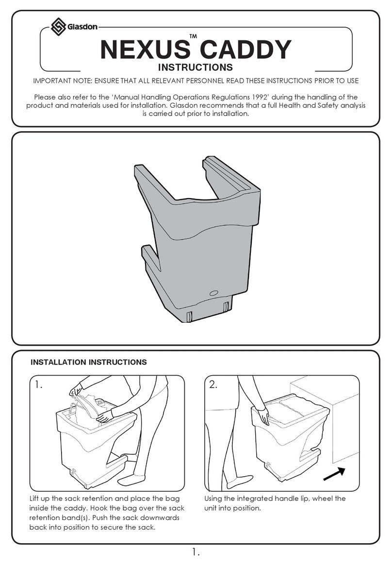
Glasdon Nexus Caddy User manual

Glasdon

Glasdon Nexus Caddy User manual

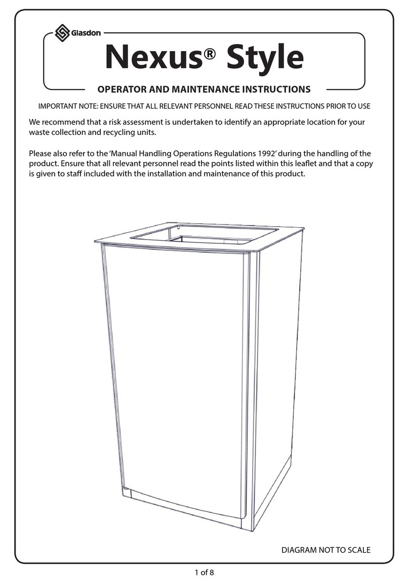
Glasdon Nexus Style Manual

Glasdon

Glasdon Nexus Style Manual

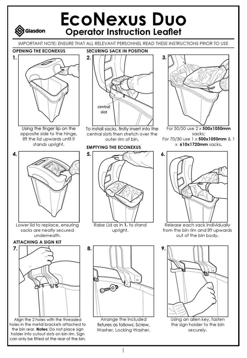
Glasdon EcoNexus Duo Manual

Glasdon

Glasdon EcoNexus Duo Manual

Glasdon VISAGE User manual

Glasdon

Glasdon VISAGE User manual

Glasdon Electra Bin Specifications

Glasdon

Glasdon Electra Bin Specifications

Popular Indoor Furnishing manuals by other brands

Regency LWMS3015 Assembly instructions

Regency

Regency LWMS3015 Assembly instructions

Furniture of America CM7751C Assembly instructions

Furniture of America

Furniture of America CM7751C Assembly instructions

Safavieh Furniture Estella CNS5731 manual

Safavieh Furniture

Safavieh Furniture Estella CNS5731 manual

PLACES OF STYLE Ovalfuss Assembly instruction

PLACES OF STYLE

PLACES OF STYLE Ovalfuss Assembly instruction

Trasman 1138 Bo1 Assembly manual

Trasman

Trasman 1138 Bo1 Assembly manual

Costway JV10856 manual

Costway

Costway JV10856 manual
moss DESIGN Caisson Credenza Assembly instructions

moss DESIGN

moss DESIGN Caisson Credenza Assembly instructions

Aquaglide FULL DECK 15.0 owner's manual

Aquaglide

Aquaglide FULL DECK 15.0 owner's manual

AREBOS AR-HE-SW30 user manual

AREBOS

AREBOS AR-HE-SW30 user manual

Till-Hilft Fulda 87005.330 Assembly instructions

Till-Hilft

Till-Hilft Fulda 87005.330 Assembly instructions

Twoey Outside 2010 quick start guide

Twoey Outside

Twoey Outside 2010 quick start guide

Hettich Easys 200 operating instructions

Hettich

Hettich Easys 200 operating instructions

The bedboss RELAX 404 Series owner's manual

The bedboss

The bedboss RELAX 404 Series owner's manual

Oeseder Möbelindustrie Bern 991 720 Assembly instructions

Oeseder Möbelindustrie

Oeseder Möbelindustrie Bern 991 720 Assembly instructions

Costway HW68469 user manual

Costway

Costway HW68469 user manual

Next ALIX A27743 Assembly instructions

Next

Next ALIX A27743 Assembly instructions

BROSA Hans Assembly guide

BROSA

BROSA Hans Assembly guide

Prodigg MINIKA PBA015T-FUR installation manual

Prodigg

Prodigg MINIKA PBA015T-FUR installation manual

manuals.online logo
manuals.online logoBrands
  • About & Mission
  • Contact us
  • Privacy Policy
  • Terms and Conditions

Copyright 2025 Manuals.Online. All Rights Reserved.