GLENSOUND ELECTRONICS LTD
GSR34 Main PCB for GSVX4 PARTS LIST
DATE 23/01/03 ISSUE No. 1
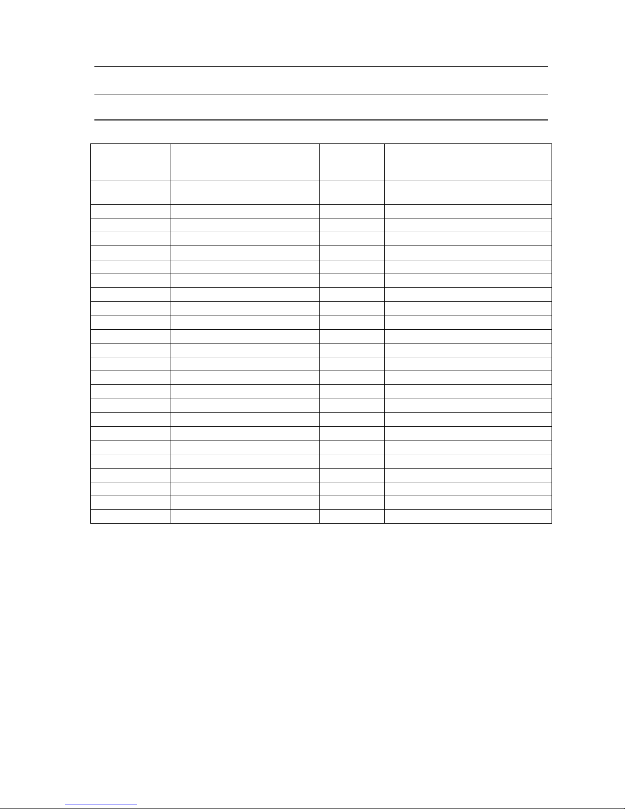
PART NUMBER MANUFACTURER OR
SUPPLIER Value or Part No. NOTES
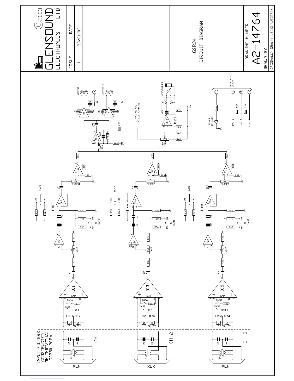
IC1,3&5 Texas Instruments INA217
IC2,4,6&13 Texas Instruments TLO74
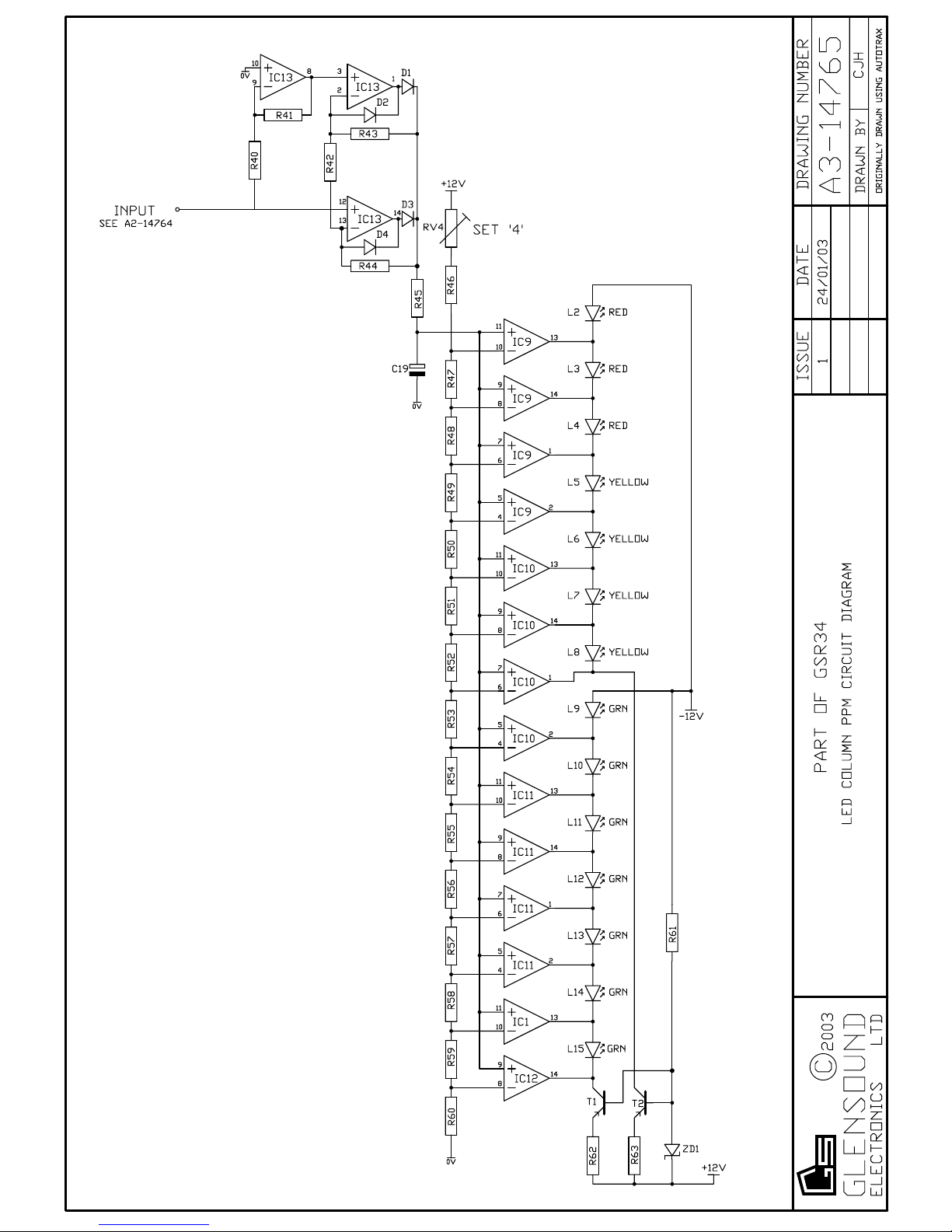
IC9,10,11&12 National Semiconductor LM339
IC14 Motorola MC33178
T1&2 Zetex ZTX550
SW1-6 APEM 25149NH DPDT centre off
RV1-3 ALPS RK09D Series 10k Lin
RV4 100k Lin
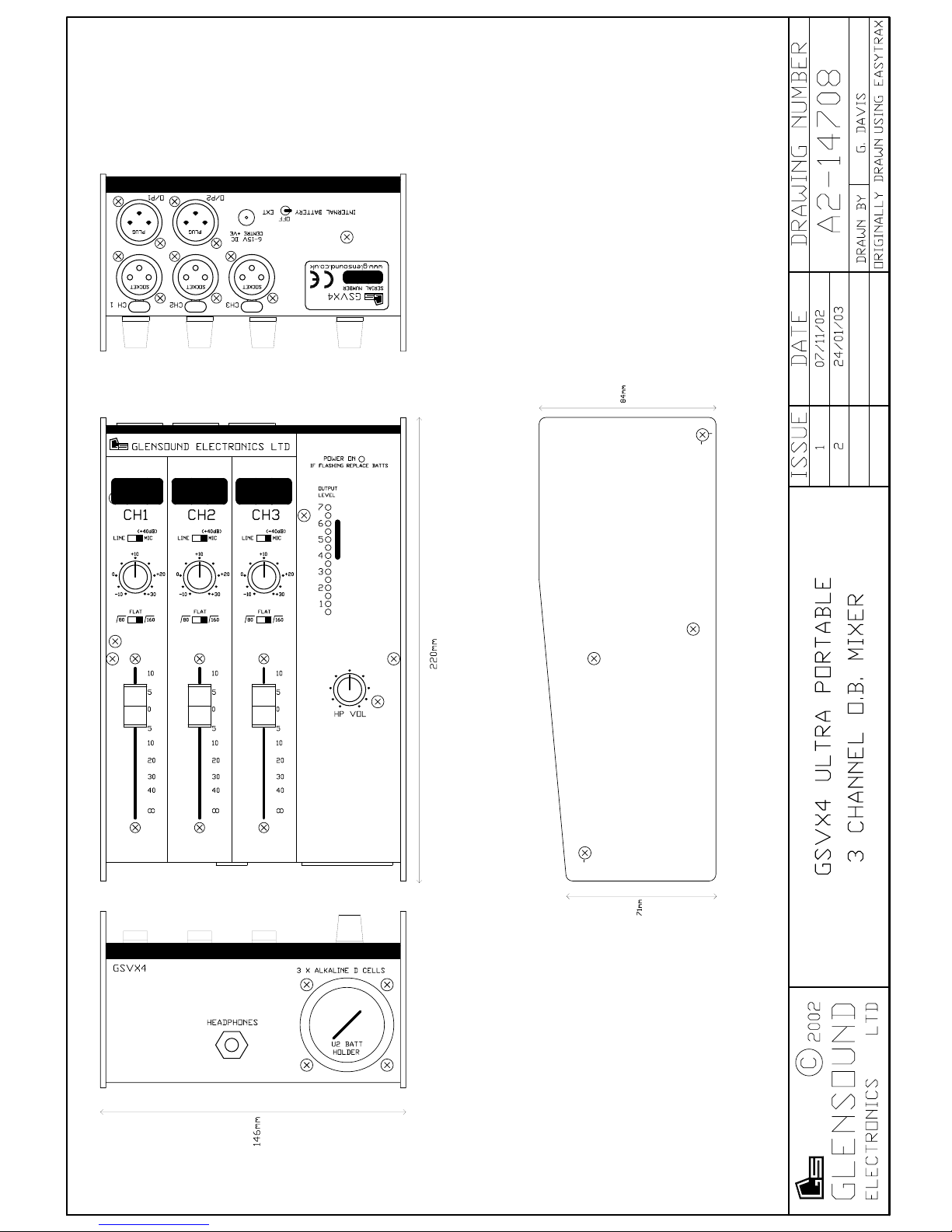
FADER1-3 Penny & Giles PGF3020/D/M..XA
TZ1-10 AVX Transguard 14V
D1-4 Any 1N4148
ZD1 Any BZX55 3V9
C1,4,5,8,9&12 Any 22/16v Radial Electrolytic
C2,3,6,7,10&11 BG Components 100N 5% 63V 222 470 series
C19 Any 10/16v Radial Electrolytic
C17,18,20,21&22 Any 22/16v Radial Electrolytic
C13-16 NITAI 4u7/35V Non Polar Electrolytic
R1,15&29 Any 10k 1% Metal Film
R2,16&30 Any 33 ohms 1% Metal Film
R3,17&31 Any 2k7 1% Metal Film
R4,5,18,19,32&33 Any 1k 1% Metal Film
R6,20&34 Any 15k 1% Metal Film
R7,21&35 Any 6k8 1% Metal Film
R8,22&36 Any 100k 1% Metal Film
R9,23&37 Any 1k8 1% Metal Film
R10,24&38 Any 3k9 1% Metal Film
R11,25,39&65 Any 10k 1% Metal Film
GSR34 PARTS LIST Page 1
GGLENSOUND ELECTRONICS LTD. Tel: +44 (0) 1622 753020
6 BROOKS PLACE, MAIDSTONE, KENT, ME14 1HE, ENGLAND +44 (0) 1622 753662