Glidecam Industries X-10 User manual

GLIDECAM®
X-10TM
Quick Setup Guide
GLIDECAM INDUSTRIES, INC.
23 Joseph Street
Kingston, MA 02364
Customer Service Line: 781-585-7900
Manufactured in the U.S.A.
© COPYRIGHT 2007-2008 GLIDECAM INDUSTRIES, INC., ALL RIGHTS RESERVED
Glidecam is registered at the PATENT and TRADEMARK office.

2

3
TABLE OF CONTENTS
1. INTRODUCTION
5
2. QUICK SETUP
7
3. ADJUSTING THE LOAD SETTINGS OF YOUR SUPPORT ARM
17
4. REMOVING THE SPRINGS FROM YOUR SUPPORT ARM
21
5. INSTALLING THE SPRINGS INTO YOUR SUPPORT ARM
29
6. SPECIFICATIONS
29
7. WARNINGS
31
8. MAINTENANCE
33
9. WARRANTY
35

4

5
CHAPTER ONE
INTRODUCTION
Congratulations on your purchase of a GLIDECAM X-10.
In order to use the GLIDECAM X-10 system, it is best to have a basic
understanding of how the system works in advance. So please make sure you read
this section before trying to setup and operate the GLIDECAM X-10.
The GLIDECAM X-10 is a highly advanced, professional camera stabilization
system that is very similar in design to the GLIDECAM SMOOTH SHOOTER;
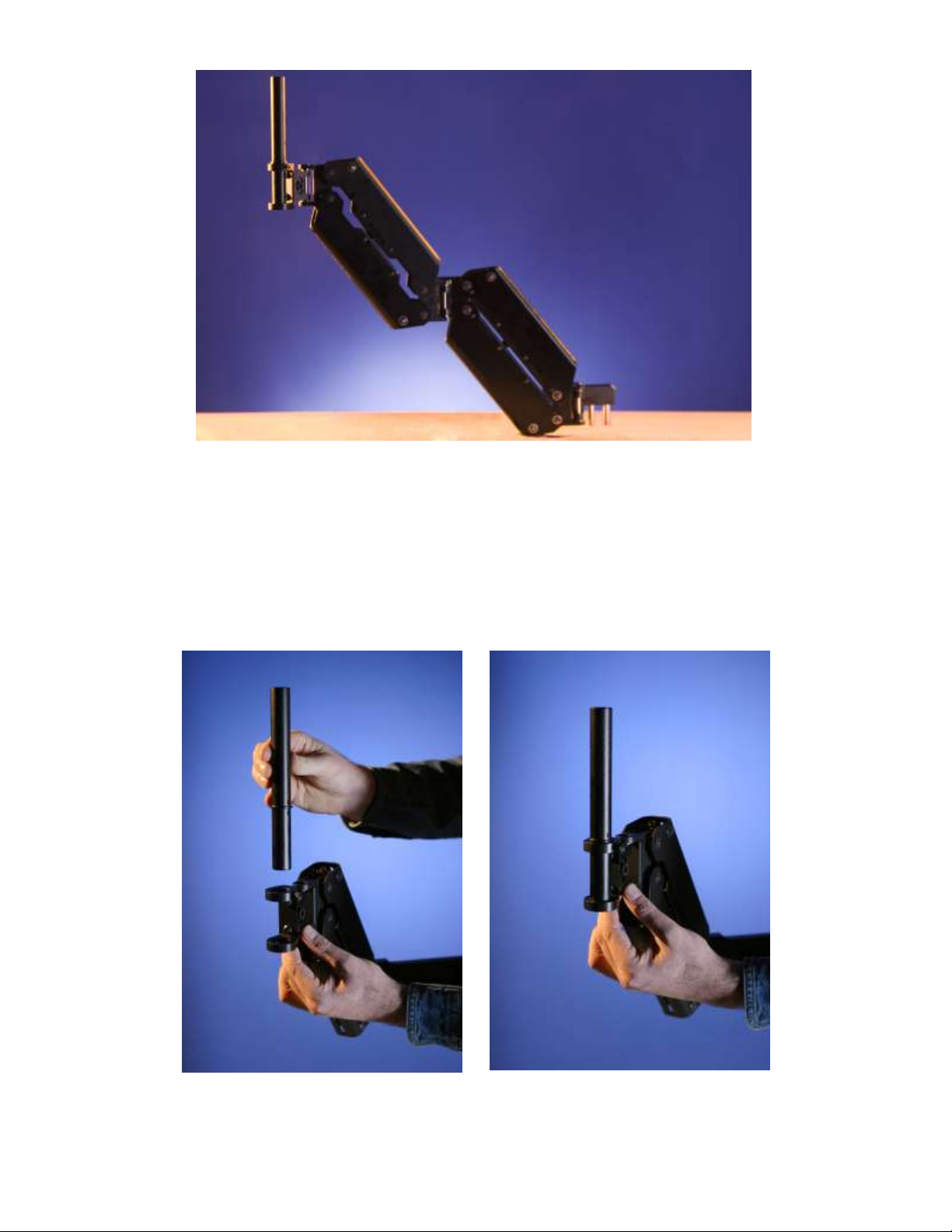
however, the X-10 comes with both sections of its SUPPORT ARM being able to
move vertically, whereas the SMOOTH SHOOTER comes with only the front
section of its SUPPORT ARM being able to move vertically. Also, the X-10
comes with a trimmable ARM-TO-VEST CONNECTOR, whereas the SMOOTH
SHOOTER’S ARM-TO-VEST CONNECTOR is not trimmable.
The GLIDECAM X-10 is designed to allow you to walk, run, go up and down
stairs, shoot from moving vehicles and travel over uneven terrain without any
camera instability or shake when used with the GLIDECAM 2000 PRO or
GLIDECAM 4000 PRO (not included). The GLIDECAM X-10 is designed for
using cameras weighing up to 6 pounds when used with the GLIDECAM 2000
PRO, or for cameras weighing from 4 to 10 pounds when used with the
GLIDECAM 4000 PRO.
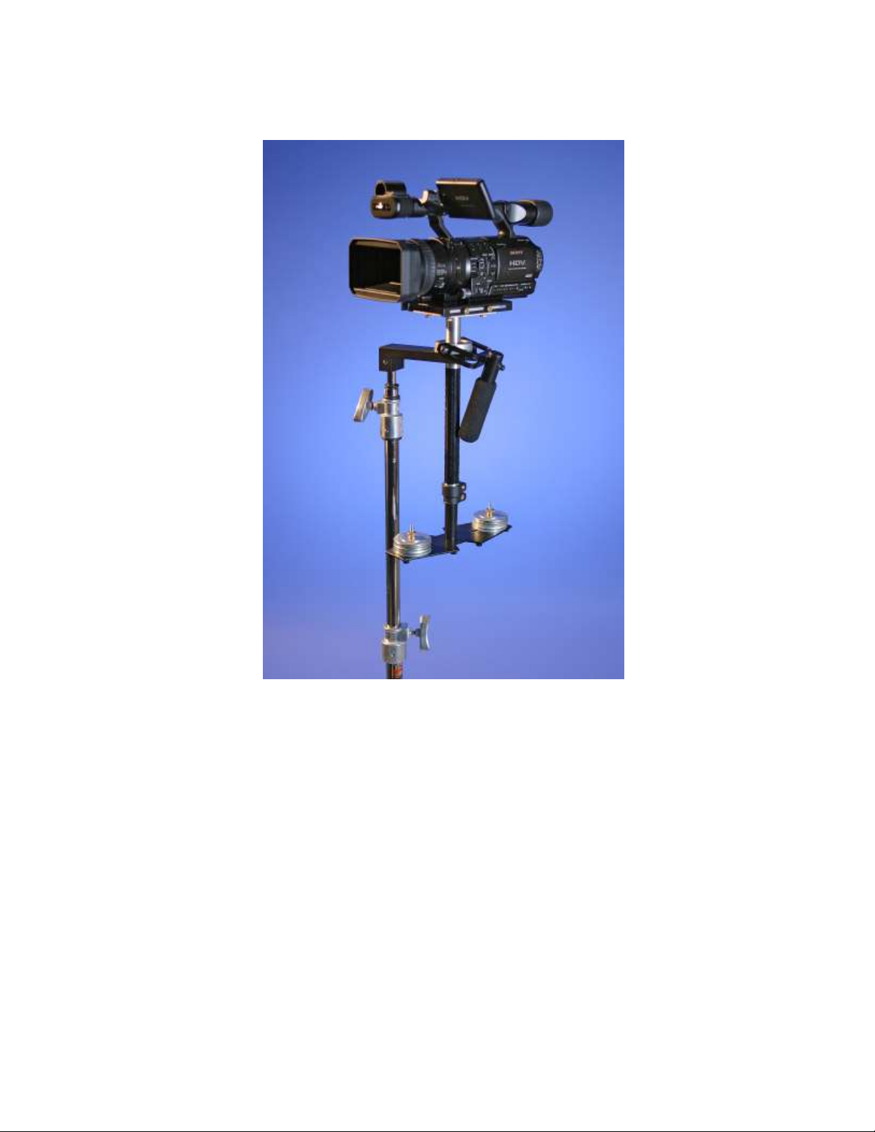
The GLIDECAM X-10 does not come with a GLIDECAM 2000 PRO or a
GLIDECAM 4000 PRO; however, it is specifically designed to be used with them,
and when they are used, they are referred to as the SLED. The SLED carries your
camera and is attached to the end of the SPRING-LOADED SUPPORT ARM,
which, in turn, is attached to the GLIDECAM SUPPORT VEST.
When using the GLIDECAM 2000 PRO or GLIDECAM 4000 PRO in hand-held
mode, your arm is carrying the weight of the SLED. However, when the 2000
PRO or 4000 PRO are used with the GLIDECAM X-10, it is the GLIDECAM X-
10’s SPRING-LOADED SUPPORT ARM that carries the weight of the SLED.
Because of this, you will now be able to shoot for extended periods of time,
whereas before, the stress associated with handholding the SLED reduced your
shooting time.
If you already own one of our hand-held stabilizers, then you will be able to use it
by simply attaching it to the end of the GLIDECAM X-10's Support Arm. Neither
the GLIDECAM 2000 PRO, nor the GLIDECAM 4000 PRO need to be modified
to work with the GLIDECAM X-10. You can use your camcorder's flip out LCD
monitor, or a monitor that is attached to the base of your GLIDECAM 2000 PRO
or 4000 PRO. This allows for remote viewing of the camera's image without
disturbing the orientation of the system.

6
While the GLIDECAM X-10 is in essence a very simple device, its simplicity
doesn’t lend ease in answering that often asked question, “how does it work?” To
answer this question would require delving into Newtonian Physics and Classical
Mechanics. We would have to explain center of gravity displacement, inertia,
reduced friction and angular motion reduction etc. However, a quick answer
reveals the GLIDECAM X-10 works by “isolating” your body’s motion from your
camera, while your camera is balanced in an isolated and relatively motionless
state. The GLIDECAM X-10'S SUPPORT ARM can be boomed up and down, as
well as pivoted in and out and side-to-side. It is the combined booming and
pivoting action of the SUPPORT ARM that isolates your motions from the camera
in a way that creates smooth camera footage.
The GLIDECAM X-10 is a highly developed and meticulously engineered camera
stabilization system. Its ability to shoot smooth imagery within its weight range is
extraordinary. It out performs all of the competition in its class, yet remains truly
economical. The GLIDECAM X-10 is the realization of the need to stabilize
lightweight cameras using the same degree of sophistication employed to stabilize
heavy cameras. Acquiring the type of smooth footage that you have always
dreamed of is entirely possible with the GLIDECAM X-10.
The GLIDECAM X-10 requires practice and understanding to achieve
professional looking results. We highly recommend that the user reads this
manual thoroughly before setting up and operating the GLIDECAM X-10. Doing
so will save you time, and will minimize the risk of damage to your camera or the
GLIDECAM X-10. It is important to perform and follow the Setup and
Operation’s procedures in the proper sequence, in order to avoid both frustration
and a possible accident.
If you need technical assistance, you can call our Technical Support Line at 1-
781-585-7900, between the hours of 10:00 AM and 5:00 PM, Eastern Standard
Time, Monday through Friday. We’re sure that once you have yo ur GLIDECAM
X-10 up and running you will find years of enjoyment with it.

7
CHAPTER TWO
QUICK SETUP
Since you will be using your GLIDECAM X-10 with either a GLIDECAM 2000 PRO or a
GLIDECAM 4000 PRO (hereafter referred to as the SLED), you should make sure that your
SLED is already setup and properly balanced. Please see the GLIDECAM 2000 PRO or 4000
PRO Manual for details regarding proper SLED setup and balancing procedures.
Figure 1 Figure 2
Included is a GLIDECAM X-10 DOCKING BRACKET, which allows you to park
your SLED while it is not in use. Securely attach and tighten the DOCKING
BRACKET onto the 5/8” RECEIVING PIN of an INDUSTRY -STANDARD C-
STAND (Not Included) as in figures 1 and 2.
It is always best to park your SLED on the provided DOCKING BRACKET, as in figure 3.
Although, if you do not currently have a C-STAND, it is acceptable to park your SLED on a
TABLE TOP and therefore not use the DOCKING BRACKET.

8
Figure 3
When you park your SLED onto the DOCKING BRACKET, make sure that the SLED’S
HANDLE is facing directly outwards as in figure 3. By parking your SLED this way on the
DOCKING BRACKET, it will be easily accessible to you when it comes time to put the SLED
onto the end of the SUPPORT ARM.

9
THE GLIDECAM X-10 SUPPORT ARM
The GLIDECAM X-10’s Dyna-Elastic™ dual-articulating SUPPORT ARM incorporates 38
precision radial bearings within its machined T6 aluminum structure. The placement and
implementation of these double-shielded bearings produce minimal friction and allow the
Dyna-Elastic™ SUPPORT ARM to pivot and boom very smoothly, and with virtually no
noise.
Four high-carbon alloy EXTENSION SPRINGS are employed within the SUPPORT ARM’s
hard-coat anodized EXOSKELETAL SHELLS. Utilizing class three levers, the energy of the
EXTENSION SPRINGS acts upon internal FULCRUM POINTS, and provides the SUPPORT
ARM with its lifting power. The spring tension is field adjustable and allows for varying
camera weights.
Our proprietary spring Inter-X-Change™ system makes the installation and removal of the
springs quick and easy. The SUPPORT ARM can be setup and used in either a Two-Spring
Mode, or a Four-Spring Mode. In the Two-Spring Mode, the SUPPORT ARM can hold a total
combined camera and hand-held stabilizer weight of 9 pounds. In the Four-Spring Mode, the
SUPPORT ARM can hold a total combined camera and hand-held stabilizer weight of 18
pounds.
A key design feature of the SUPPORT ARM is that it incorporates our Light-Force™
technology. This means that literally only a "light" force or effort is required by the operator to
hold the arm at any given position, or to boom the arm up and down. It is this Light-Force™
feature that provides the operator with the optimum amount of camera buoyancy or float.

10
Figure 4
The GLIDECAM X-10 SUPPORT ARM (figure 4) comes pre-configured with four
EXTENSION SPRINGS, which are already installed. These SPRINGS are also
preset to their weakest LOAD SETTING. Later, in the CONFIGURATION
SECTION, we will discuss how to make adjustments to the arm in detail. For
now, leave the SPRINGS in the SUPPORT ARM at their factory setting.
Now, install the BLACK ARM POST into the ARM POST CLAMP at the end of
the SUPPORT ARM, as in figures 5 and 6.
Figure 5 Figure 6

11
Figure 7
Tighten the ARM POST into the ARM POST CLAMP, making sure to align the
NOTCHES in the ARM POST so that they face the TIGHTENING SCREW as
shown in figure 7. Do not OVERTIGHTEN this PLASTIC TIGHTENING
SCREW, for this could damage the THREADS. The reason that the TIGHTENING
SCREW is made of plastic is so that it will not scratch the ARM POST.
THE GLIDECAM X-10 SUPPORT VEST

12
The GLIDECAM X-10 SUPPORT VEST is lightweight, comfortable and can be adjusted to fit
a wide range of operators. High endurance, dual density, EVA foam padding and integral T6
aluminum alloy create a vest that can hold and evenly distribute the weight of the system across
the operator's shoulders, back, and hips. For safety, quick-release, high-impact buckles allow
the vest to be removed quickly. The VEST’s outer shell is made of 1000 denier cordura fabric
and 7-panel seat belt strapping, noted as being the best in the industry.
The GLIDECAM X-10 SUPPORT VEST incorporates a unique and proprietary ARM-TO-
VEST CONNECTOR that allows the angle of the SUPPORT ARM to be adjusted relative to
the SUPPORT VEST. This trimming mechanism allows you to neutralize the weight of the
SUPPORT ARM relative to your body’s center of gravity. When set correctly, the effort
required while shooting is greatly reduced. Another unique and proprietary feature of the
ARM-TO-VEST CONNECTOR is that it allows the SUPPORT ARM to be attached and
removed from the VEST without affecting the operator’s selected trim settings.
Figure 8
Put the GLIDECAM SUPPORT VEST on next. Adjust the STRAPS on the VEST until the
VEST fits you comfortably; however, make sure that the VEST is not on too loosely, for it
needs to bear the combined weight of the SUPPORT ARM and SLED. Also, you should make

13
sure that the very bottom of the vest is not positioned so low on your torso that it inhibits your
legs from moving up and down fully if you are planning on walking up and down stairs or
walking over uneven terrain.
Figure 9
Connect the GLIDECAM X-10 SUPPORT ARM to the GLIDECAM SUPPORT
VEST. First, note the location of the two RECEIVING HOLES in the ARM
CONNECTOR BAR shown by the solid arrow in figure 9. Next, carefully align
and guide the two STEEL PINS located on the back end of the RIGID ARM down
into the two RECEIVING HOLES. Make sure that the arm is fully inserted into
the RECEIVING HOLES.
To change the horizontal bar (bridge plate) attached to the vertical plate from right to left or
left to right, unscrew the four screws. Then flip it around and attach it again by using the
four screws, as shown by the dotted arrow in figure 9.
The two knobs on the front of the bridge plate are to adjust the arm in front of your body.
When you tighten the top you must also loosen the bottom screw to get the sled to come
towards you and when you tighten the bottom you must loosen the top at the same time to
get the sled to move away from you. The two knobs on the top and bottom of the bridge
plate are to adjust the arm left to right in front of your body. Once you have the desired
position make sure that both bolts are tight. The adjustment gets the sled to the position you
most often use without having to apply much pressure to keep it there.

14
Figure 10
If everything has been done properly so far, you should now have the SUPPORT ARM
attached to the VEST, as in figure 10 (without the camera).
Figure 11 Figure 12

15
You can now attach the SUPPORT ARM to the SLED by carefully aligning and
guiding the ARM POST all the way into the bottom of the SLED HANDLE as in
figures 11 and 12. After you have done this, hold onto the SLED HANDLE
firmly so that as you carefully lift the SLED straight up and out of the
DOCKING BRACKET, you can make sure that the weight of the SLED is in the
control of your ARM and not the SPRING-LOADED SUPPORT ARM. Now
gradually let the SUPPORT ARM take over the job of holding the weight of the
SLED. If your SLED is too heavy for the SUPPORT ARM at its current LOAD
SETTING, the weight of the SLED will angle the SUPPORT ARM downwards. If
your SLED is too light for the SUPPORT ARM at its current LOAD SETTING,
the SLED will angle the SUPPORT ARM upwards.
If your SLED is the correct weight for the SUPPORT ARM at its current LOAD
SETTING, the ARM will remain level as in figure 13.
Figure 13
If your SLED is too heavy for the SUPPORT ARM, in the ARM’S current factory
setting, you will need to increase the SPRING TENSION of the ARM by
following the procedures outlined in the ADJUSTING THE LOAD SETTINGS OF
YOUR SUPPORT ARM section of this manual.
If your SLED is too light for the SUPPORT ARM, in the ARM’S current factory
setting, you will need to decrease the LOAD CAPACITY of the ARM by
removing one of the SPRINGS as outlined in the REMOVING THE SPRINGS
FROM YOUR SUPPORT ARM section of this manual.

16
Figure 14*
The GLIDECAM X-10 is designed to work best when the system is operated with
the SLED positioned directly in front of you, as in figures 14 and 15. This
position allows you a clear view of either the LCD MONITOR on your camcorder
or the LCD MONITOR on the BASE PLATFORM of your SLED.
Figure 15*
Also, you should note that when using the GLIDECAM 2000 PRO or GLIDECAM
4000 PRO in HAND-HELD mode, you were instructed to firmly hold onto the
HANDLE. This was due to the fact that you had to support the entire weight of
the system in your hand. However, now that the X-10 SUPPORT ARM is holding
the weight of the system, holding the HANDLE gently, as in figure 15, yields
superior results.
*Please note that these photographs actually show the GLIDECAM SMOOTH
SHOOTER; however, the GLIDECAM X-10 should be positioned in the same way.

17
CHAPTER THREE
ADJUSTING THE LOAD SETTINGS
OF YOUR SUPPORT ARM
In order to change the LOAD SETTING of the SUPPORT ARM, you will need to
either change the SPRING TENSION within the ARM, or add or remove a
SPRING from the ARM. Both of these changes can be made using the supplied
ALLEN WRENCHES (not shown).
When you receive your GLIDECAM X-10, it comes pre-configured with four
SPRINGS already installed and set to their weakest SPRING TENSION setting.
In order to adjust the SPRING TENSION in the SUPPORT ARM, you must
first make sure that the SLED is not on the end of the ARM and that the ARM
is not attached to the VEST. You must also make sure that the ARM is not
under load and that it is angled upwards.
Figure 16
To increase or decrease the SPRING TENSION within the ARM, you will need to
either lengthen or shorten the SPRING with an ALLEN WRENCH as shown in
figures 16 and 17.

18
Figure 17
Figure 18

19
When you change the length of the SPRINGS, you will be able to see their
positions change in the GUIDE SCALE WINDOWS located on the top and bottom
of the SUPPORT ARM (figure 18).
The MARKINGS next to the GUIDE SCALE WINDOWS indicate the different
LOAD SETTINGS. You can set the SPRINGS from 0 to 6 and anywhere in
between, with 0 being the weakest, and 6 being the strongest.
If your SLED is too heavy for the SUPPORT ARM, you will need to increase the
SPRING TENSION of the ARM. If your SLED is too light for the SUPPORT
ARM, you will need to decrease the SPRING TENSION of the ARM.
Additionally, you may need to either add or remove a SPRING from each section
of the SUPPORT ARM to either increase or decrease the ARM’S load -carrying
capacity. Your goal in making these adjustments is to support the weight of the
SLED while the ARM remains level, as shown in figure 13.
When you use the SUPPORT ARM with only two SPRINGS in it, it can hold a
maximum load of 9 pounds at its strongest setting. When you use the SUPPORT
ARM with four SPRINGS in it, it can hold a maximum load of 18 pounds at its
strongest setting. It should be pointed out that the maximum loads above refer to
the weight of your CAMERA and SLED combined, and not just the weight of your
CAMERA alone.
NOTE: The GLIDECAM X-10 SUPPORT ARM is optimized to take advantage
of the principle that the more inert a camera system is, the more stable it is. In
other words, the heavier your camera or combined camera and SLED are, the
more stable your resulting footage will be. Therefore, you should always try to
use the GLIDECAM X-10 SUPPORT ARM at its maximum LOAD CAPACITY
for a given SPRING combination. In practice, this optimization will occur
when a 9-pound SLED is used with only two SPRINGS installed in the arm, or
when an 18-pound SLED is used with four SPRINGS installed in the arm.
We have provided six STEEL WEIGHT PLATES (figure 19) with the
GLIDECAM X-10 so that you may use them to increase the total weight of your
SLED. This is so that the combined weight of your CAMERA and SLED can
equal approximately 9 pounds when used with two SPRINGS in the ARM, or 18
pounds when used with four SPRINGS in the ARM.
In addition to the STEEL WEIGHT PLATES, we have also provided two different
types of ARM POSTS; one black, lightweight ARM POST, and one heavy,
stainless steel ARM POST. These are shown in figure 20.

20
Figure 19
The heavy, stainless steel ARM POST weighs approximately 1.25 pounds and can
be used to quickly increase the total load at the end of the ARM. Increasing the
load at the end of the SUPPORT ARM is, in effect, equivalent to increasing the
weight of the SLED.
Figure 20
Table of contents
Other Glidecam Industries Camera Accessories manuals
Popular Camera Accessories manuals by other brands

Marshall Amplification
Marshall Amplification CV6-DH Series installation instructions

Panasonic
Panasonic AWPH405N - PAN/TILT CAMERA operating instructions

D-Link
D-Link DCS-60 Technical specifications

Peimar
Peimar PSI-J51-48-BT manual

GreenWorks
GreenWorks 29717 Original instructions

Teknoware
Teknoware TAPSA CONTROL TKT65 Installation and maintenance instructions