Glider.it Diana 3 Instructions for use

www.glider-it.com

Construction manual
-Place a pad on your workbench to protect the surface of your model
- Then you can start with the removal of the wings. In the example
shown here, K T – X10 are installed on the flaps and on the inner
ailerons. K T - H 08A are used on the outer ailerons. Prepare the servo
frames and grind them thoroughly at the bottom and on the side edges.
This is the only way to ensure a proper adhesive bond.

- Next, they glue a frame made of crepe tape around the servo shafts.
This is for protection and is needed to mark the exact positions of the
servo frames.

- The edges of the servo bay can be slightly reduced. Original have this
6mm width. If you shorten this to half, it makes it easier to install the
servo frames
- The recesses for the rudder horns are already prepared as standard.
These are used for orientation and the position of the servo frame is
marked. With the help of a geotriangle, a line (90 degrees to the hinge) is
drawn

In the outer ailerons, the rudder horns come to the bottom (classic
linkage) and there the position can be transmitted directly
-On the flaps and the inner ailerons, the rudder horns come to the top
(crossover linkage) and there the position must first be transferred from
the top to the bottom.
-To do this, as explained above, they draw a line at a 90-degree angle to
the hinge. tarting from the recess for the rowing horn.
- They draw this line to the end bar and then transfer the position to the
lower shell

From this point, in 90 degrees to the hinge, you can then draw the
required lines
- Next, roughen the surface in the servo shaft and then all adhesive
surfaces (servo bay and servo frame) are degreased
In the next step, the servo frames are prepared for gluing.
There are 2 possibilities: Either they wet the servos with release wax or
they wrap them in cling film. If this is not done carefully, you will not get
the servos removed later because they are firmly glued.

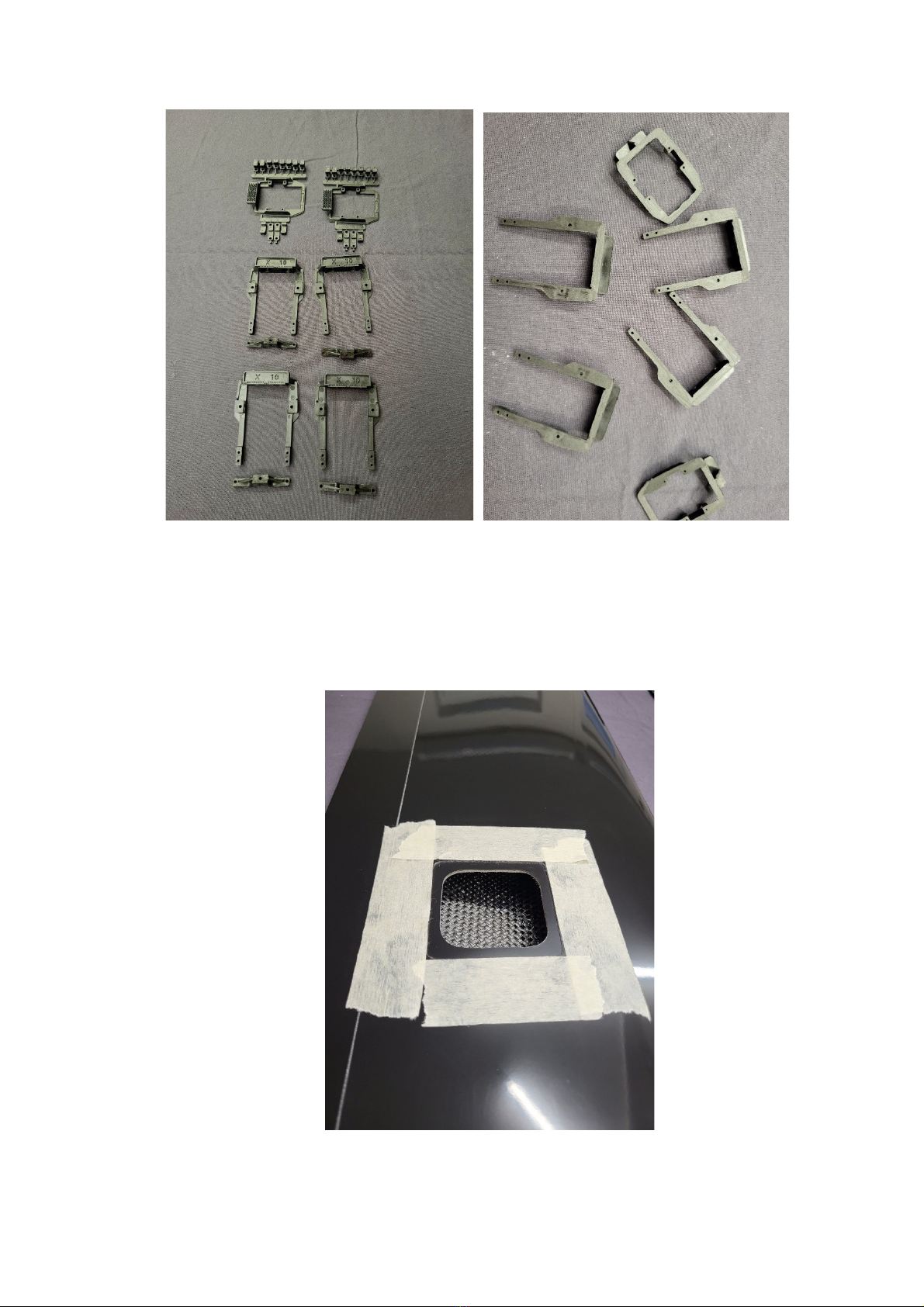
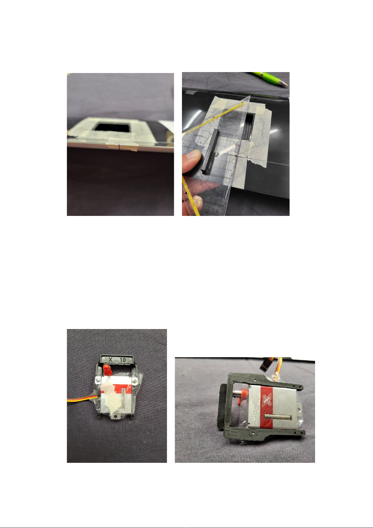
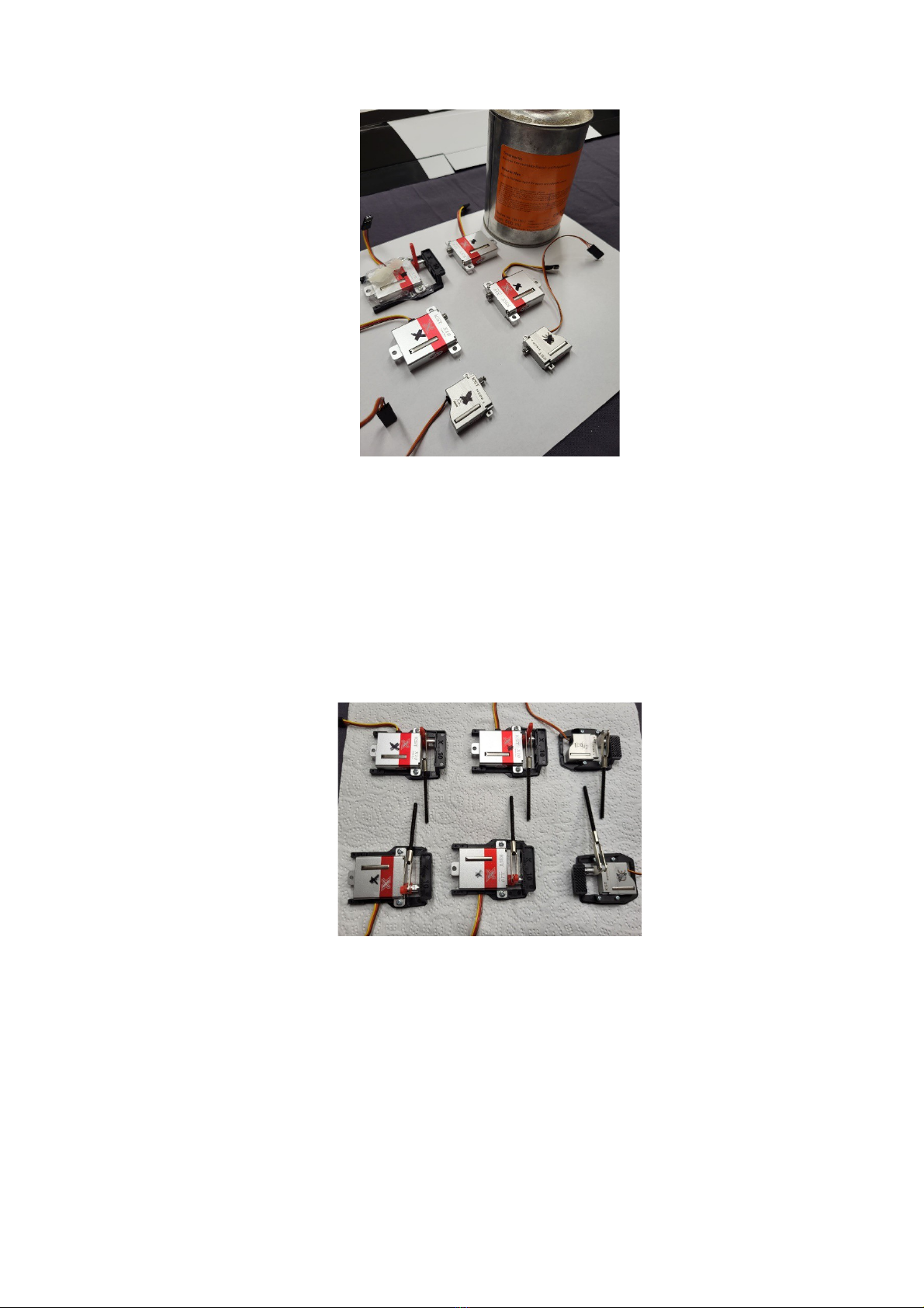
- Now all servos are screwed into their frames.
Important: With servo arm, fork head and a linkage (the length of the
linkage does not matter here)
The rear crossbar on the X10 can be omitted. The servo is fixed at 3
points (2 screws + the counter bearing) and this is sufficient
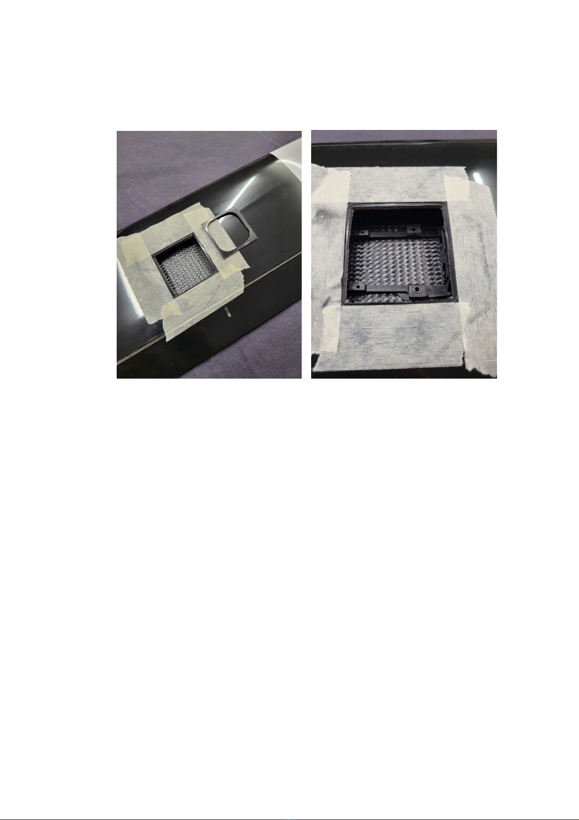
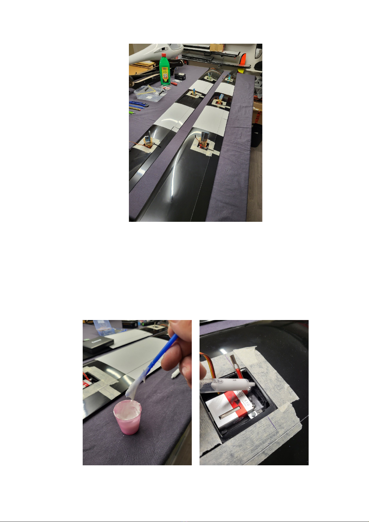
- Now the 6 servo frames can be glued in. For this they either use Uhu
Endfest or you mix a mumble of 24h resin with cotton flakes and some
thixotropic agent.
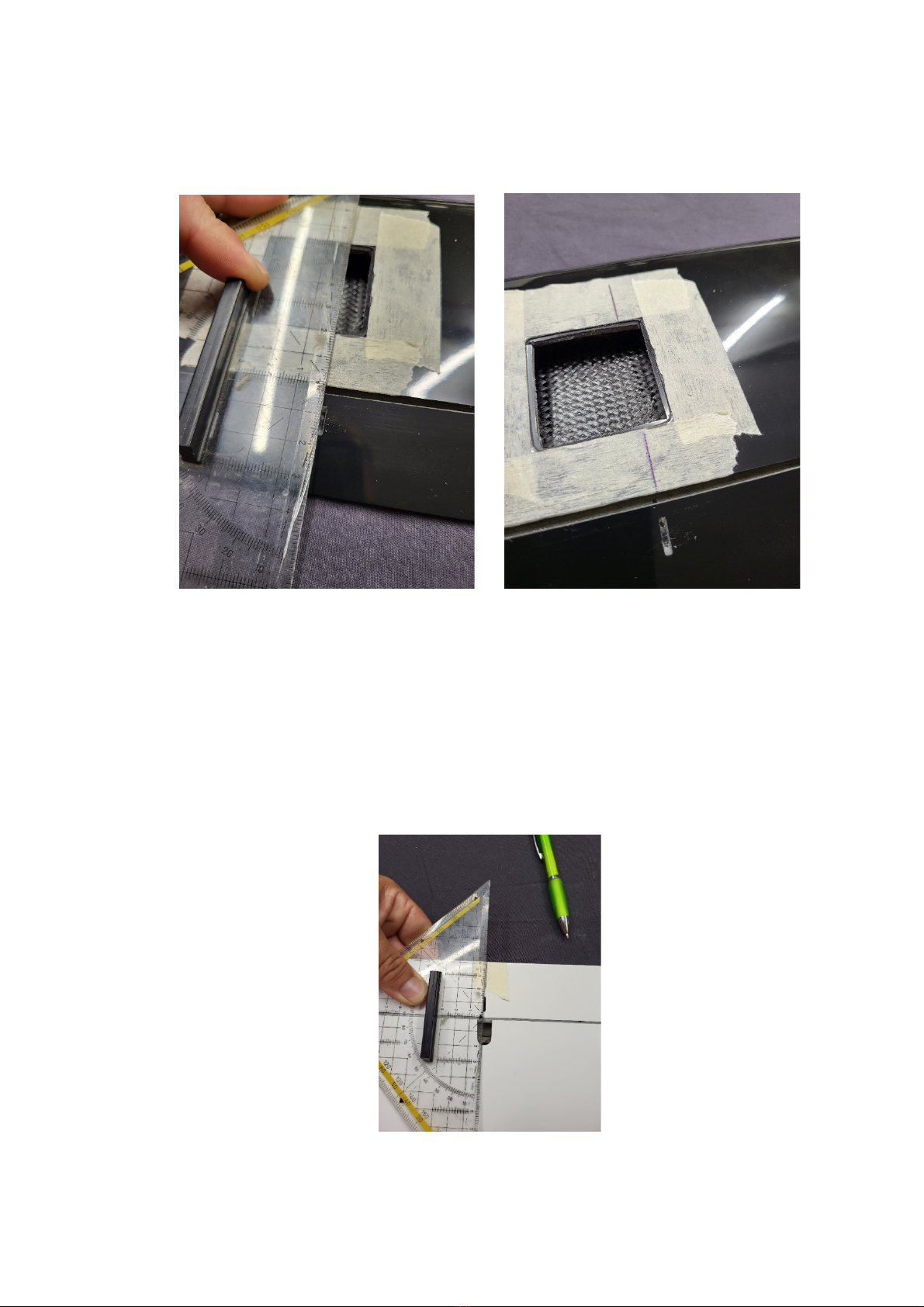
If your glue is ready, wet the places in the servo bay and the servo
frames with the glue with a brush. Place the servo frames in the desired

position and align it cleanly with the help of the previously drawn lines.
- After everything is in it, the position is checked again and the whole
thing is weighed down a little.
For this you can use small cups with 100g - 200g lead in each

- Once the whole thing has hardened, the ribs of the counter bearings
are glued to the lower shell.
For this again use an adhesive or mummy. It is important that this must
be touched very toughly, it must no longer flow. Pull the glue into a small
syringe. This makes it easy to bring the adhesive to the desired position.

- It is important here that no glue comes to the ball bearing
- When everything has hardened, the installation of the rowing horns
continues
Before the rudder horns can be positioned, the prefabricated cut-outs
must be reworked a little

- With the flaps and the inner ailerons, the opening is extended towards the
hinge so that you can continue with the rudder horn to get the pivot point
further towards the hinge

- If all cutouts are adjusted so far that the rudder horns can be glued in
then the rudder horns are ground and degreased. The cut-outs in the
oars should also be made dust-free and grease-free. This is the only way
to create a proper bonding.
- tart with the outer ailerons

Put some glue in the opening for you rowing horns and brush the rowing
horns a little with it.
After you have positioned the rudder horns, it is best to mount a pole.
You should prepare this beforehand. The exact length does not matter
because it only serves to align the rowing horn cleanly
- After the rudder horns are fixed to the outer ailerons (glue hardened),
the same procedure continues on the inner ailerons and the flaps

- With the flaps you should grind away a little bit of the plastic of the
frame because otherwise this is in the way of the linkage.
- As soon as the rudder horns are firm, they manufacture the appropriate
linkages for all linkages in the area, so that the desired deflections can be
achieved
- Next, the electrical connection between the hull and the surface is
created.
The whole thing is firmly installed on the fuselage and floats in the
surfaces.
wings - male MPX
fuselage - female MPX

ince 3 servos per area are to be connected and the connector has 6
poles, the conductors (red) are soldered together on 2 pins.
The location on the fuselage is marked and then transferred to the root
rib of the wings

- Then the whole thing is separated and adjusted with a file until the plug sits
sucking in the opening

- Before the plug is glued in, the exact position is transferred to the root
rib.
Apply some crepe tape to the root rib. At the position where later the
counterpart of the plug should sit
- Now draw the section with a pen
- Then they make a generous cut-out around the marked spot on the root rib.
The plug connection on the surface side will be floating, so the cut-out should
be made large enough.

- As a next step, the cables are prepared for the surfaces and cut to the
correct length

- If the cables are all prepared, the MPX connectors are soldered. If you
have the opportunity, you can then pour the whole thing cleanly.
To protect the cables, it makes sense to pour in a fabric hose
- That the cables will not rattle later in the surface, before pulling in the
cables, small foam pieces attached. These can be fixed to the cable with
a drop of second glue.

- For the connection between cable set and servo you can choose
between 2 variants. older directly or crimp connectors.
If you decide on a plug connection, it is important to secure it with a
good tape
- As a last step, the servo covers are now adjusted and attached
Other Glider.it Aircraft manuals
Popular Aircraft manuals by other brands

SOL paragliders
SOL paragliders Flexus LOTUSOne manual

DG Flugzeugbau
DG Flugzeugbau DG-500 ELAN Orion Flight manual

McDonnell Douglas
McDonnell Douglas 369H Series Appendix

Hyperflight
Hyperflight X-res instruction manual

Crosswinds Aviation
Crosswinds Aviation DA20 C1 Eclipse Training manual

Cessna
Cessna 152 1978 Pilot operating handbook