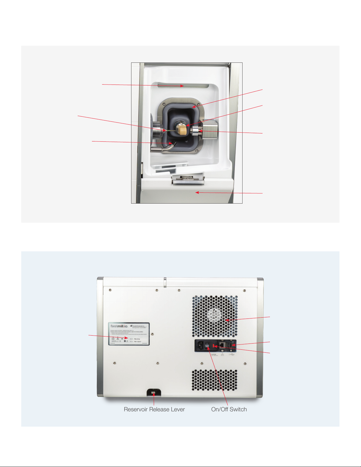
Glidewell Dental fastmill.io User manual

User Manual

Components ........................................................................3
Getting to Know Your Mill ..................................................3
Rear Panel Components ...................................................4
Power Entry Module and USB Port ...................................5
Initial Setup...........................................................................5
LED Status Strip...................................................................6
Running the fastmill.io™In-Office Unit....................................6
Loading a Milling Material ..................................................6
General Operations...............................................................8
Loading Material................................................................8
Replacing a Bur (Tool) and Bur Life....................................8
Routine Maintenance............................................................9
Coolant .............................................................................9
Coolant Concentrate Hazard and
Warning Information ..........................................................9
Hazard Identification and First Aid Measures .....................9
Preparing Coolant .............................................................9
Cleaning and Refilling the Coolant Trough........................10
Cleaning the fastmill.io In-Office Unit................................10
Maintaining the Spindle ...................................................11
Removing/Replacing the Fuse.........................................12
Repair .............................................................................13
Notes .................................................................................13
Troubleshooting Guide........................................................14
Symbols Glossary...............................................................15
System Specifications ........................................................15
Contents
Page 2 of 15

Components
Getting to Know Your Mill
Door (open)
LED Light Showing White
Reservoir Door (open)
Coolant Reservoir
Machining Chamber
Door Push-Button
Page 3 of 15

Boot
LED Status Indicator Light
Bur (Milling Tool)
Coolant Spray Nozzle
Reservoir Door
Milling Material Holder
Fan
USB Port
Technical Plate
Reservoir Release Lever
Fusebox
On/Off Switch
Material Tool Probe
Rear Panel Components
Page 4 of 15

USB Port
Fuse Cover
Power Switch
AC Input
Power Entry Module and USB Port
Inital Setup
1Using two or more people, place the mill on a sturdy
table, desk or countertop capable of supporting 150 lbs.
Make sure the mill has at least a four-inch clearance on
all sides.
To prevent injury, two or more people should lift
and place the mill in its location.
2Set up the computer components: monitor, keyboard
and mouse close to the mill.
3As a safety precaution, always connect the power cords
for the mill, computer and monitor to easily accessible
three-pronged grounded power outlets.
Make sure the power cord connections are
accessible at all times so disconnections can be
made during an emergency.
4Connect the computer to the mill with the USB cable.
5Make the coolant using the directions in the Preparing
Coolant section on page 9. (Coolant warning and hazard
information are in the Routine Maintenance section of
these instructions on page 9.)
6Pour the prepared coolant into the reservoir to the MAX
fill line (1500 mL) on the right side of the reservoir.
7Slide the reservoir into the mill until it clicks into the
locked position with the reservoir door completely
closed.
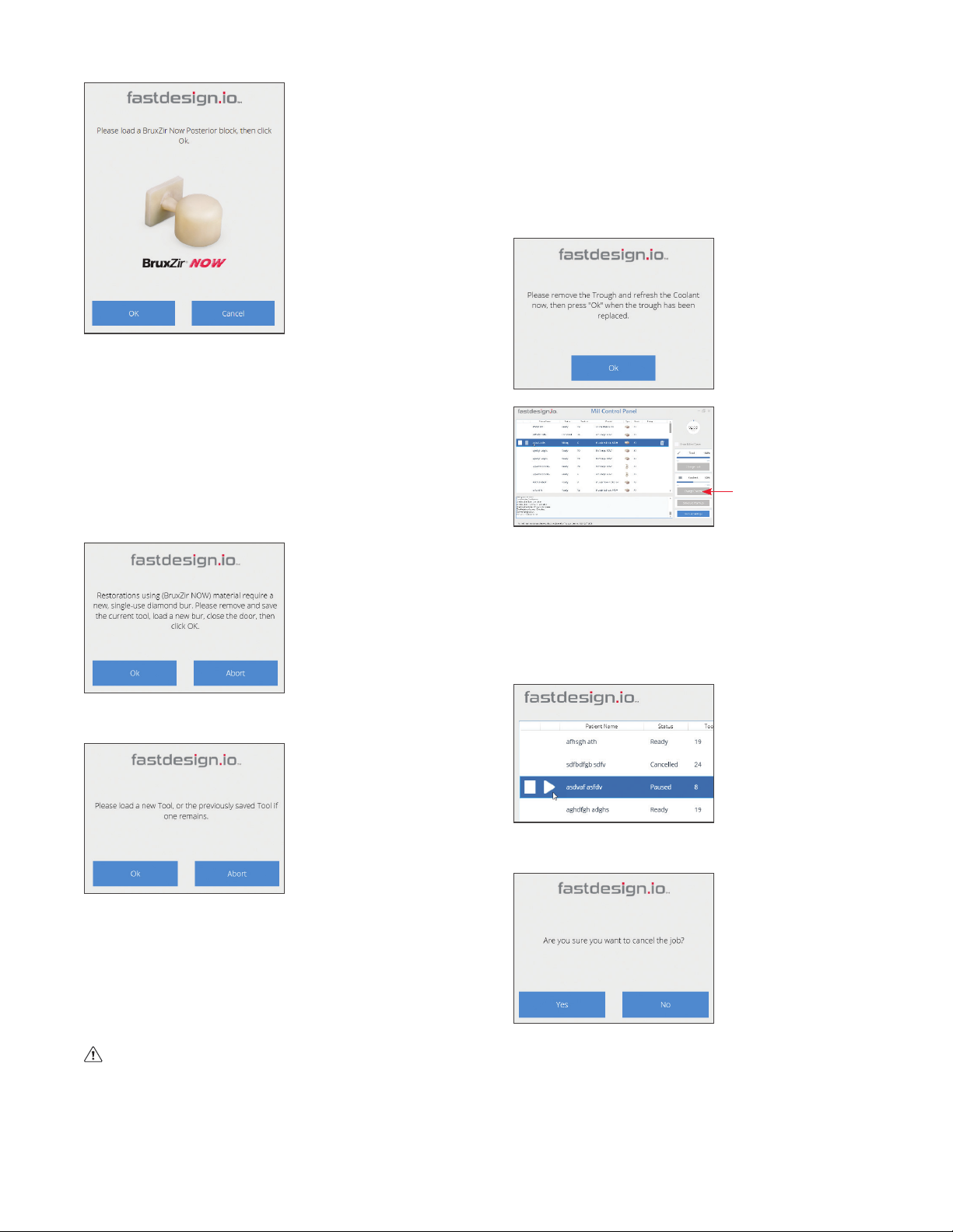
8Turn on the computer and the mill. The CloudPoint®Mill
Control Panel will open onto the computer screen.
9Click “CHANGE TOOL.”
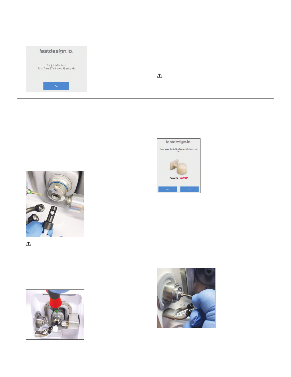
10 Open the mill door, remove the collet pin from the spindle
(collet), and save the collet pin.
Keep a bur (tool) or collet pin in the spindle at all
times. Leaving the spindle empty can damage the
collet.
11 Insert the bur needed for the initial case, depending on
material type, into the spindle and click “OK” on the
computer screen.
12 If ready to mill, continue to the next section.
13 Allow the mill to go into a sleep mode when all jobs have
been completed for the day. At the scheduled time,
during off hours, the mill will “wake up” and warm up the
spindle for about 15 minutes.
Page 5 of 15

LED Status Strip
The basin is lit by a color-coded LED light. This light
allows users to see if the mill is operating properly, has
malfunctioned, or needs a coolant change. The color
definitions are as follows:
LED Colors Reference Table
Color Description
Bright White Idle/Homed
Blue Job Starting
Cyan Job Halfway
Bright Green Job Close to Completion
Green Job Complete
White Un-homed/Homing
Magenta Coolant Change Needed
Red Error
Yellow Warning
No Light Sleep/Off
Running the fastmill.io™
In-Office Unit
1Turn on the computer and the mill. The CloudPoint Mill
Control Panel will open onto the computer screen.
2The mill will go through a self-check sequence, which
will verify that the motion control and other systems are
working correctly.
3After the fastdesign.io™Software sends the patient cases
to the Mill Control Panel, the cases will download onto
the computer screen. Select a patient case and click the
play button next to the patient name.
Loading a Milling Material
4At the material prompt, load the material selected for the
case.
a) Open the mill door.
b) Insert the mandrel into the milling material holder with
the dimple in the mandrel facing up.
To prevent punctures or tears in the area behind
the milling material holder (boot), do not push
to torque driver into the boot when tightening/
loosening the retaining screw.
5 Tighten the retaining screw with the torque driver until the
handle clicks.
DO NOT overtighten the retaining screw.
6 Confirm that the correct material is loaded and click
“OK.”
Mill lit by Green LED light
indicating job complete.
Page 6 of 15

NOTE about initial setup and run information: If
prompted to change the bur (tool) after the collet
pin was replaced with a new bur, click “No” and go
to Step 9 in this section.
7At the tool prompt, insert the new bur for the selected
material into the spindle (collet) and click “OK” on the
computer screen.
BruxZir®NOW Tool Prompt
Composite Tool Prompt
8 Close the mill door.
NOTE: BruxZir NOW burs are for single use milling. The
mill will prompt you to change out the bur whenever the
selected milling material is BruxZir NOW.
9Milling will begin automatically after the door is closed.
To prevent injury, keep hands out of milling
chamber while the spindle is running.
10 While milling, the timer on the top right corner will
indicate how much time has passed. The blue outer ring
of the timer indicates how much longer the process will
take to complete.
11 At the coolant prompt, click “CHANGE COOLANT” on
the Mill Control Panel and follow the coolant instructions
in the Maintenance section of this guide.
12 The process can be paused at any time by clicking the
pause button left of the selected case.
13 After pausing, press the play button to continue milling
or press the abort button to cancel the job. (The white
square button, next to the play button, is the abort
button.)
Left Corner of Mill Control Panel
After the abort button is pushed, confirm job cancellation
by pressing “YES” after the prompt.
Page 7 of 15

14 When the job is finished, click “OK”, then use the torque
driver to loosen the retaining screw holding the material
and remove the restoration.
15 Finish the restoration according to the instructions for the
material.
16 At the end of the day, confirm that a bur or collet is in
the spindle (collet). The mill will go into sleep mode after
office hours. At the scheduled time, off hours, the mill
will “wake up” and warm up the spindle for about 15
minutes.
Keep a bur or collet pin in the spindle at all
times. Leaving the spindle empty can damage the
collet.
General Operations
Loading Material
1 After pressing the play button, the mill will prompt you
to confirm that the correct material is loaded for the
particular case.
2 Open the mill door and insert the mandrel into the
material holder with the dimple facing up.
To prevent tears or punctures in the area behind
the material holder (boot), do not push the torque
driver into the boot when tightening/loosening the
retaining screw.
3Tighten the retaining screw with the provided torque
driver until the handle clicks. DO NOT over tighten the
retaining screw.
4Confirm that the correct material is loaded and click
“OK.”
NOTE: BruxZir NOW burs are for single-use milling. The
mill will prompt you to change out the bur whenever the
selected milling material is BruxZir NOW.
Replacing a Bur (Tool) and Bur Life
1Click “CHANGE TOOL.”
2Open the mill door and remove the current bur.
3Insert the new bur for the selected material into the
spindle (collet) and click “OK” on the Mill Control Panel.
4Close the mill door.
Page 8 of 15

Routine Maintenance
Coolant
Glidewell Dental Mill Coolant Concentrate, also known as AmberCut™389K, is a synthetic machining coolant concentrate.
The prepared coolant used in the mill does not contain any significant hazardous materials at a dilution of 4.8%–6.3%.
Nevertheless, during the dilution process and the handling of used coolant, safety glasses and gloves should be worn.
Contact the manufacturer of AmberCut 389K to obtain the Safety Data Sheet (SDS).
Coolant Concentrate Hazard and Warning Information
Eye and Skin Irritant
Hazard Identification and First Aid Measures
a. EYES – Contact with eyes may cause moderate eye irritation. Rinse eyes with large quantities of water if eyes
become irritated.
b. SKIN – Prolonged or repeated exposure to the skin may cause irritation. Rinse skin with large quantities of water if
skin becomes irritated.
c. INHALATION – The coolant is not an inhalation hazard under normal conditions. If respiratory irritation does occur,
move the person into a well-ventilated environment or into the fresh air.
d. INGESTION – Ingestion may cause stomachache, nausea, diarrhea, vomiting, and headaches. If ingestion occurs,
dilute stomach contents with water and get medical attention. Do not induce vomiting.
Preparing Coolant
Make 1500 mL of coolant in the provided fastmill.io pitcher. With eye protection
and gloves on, add 95 mL of Glidewell Dental Coolant Concentrate to the 95 mL
fill line, then fill with distilled or reverse osmosis water to the 1500 mL fill line and
mix. Pour the prepared coolant into the trough to the MAX fill line (1500 mL) on
the right side of the trough.
Materials Tool Replacement Schedule
Sintered Zirconia (BruxZir NOW, BruxZir Esthetic NOW) After Every Restoration (BruxZir NOW is shipped with a
green-striped BruxZir NOW tool for each block)
Glass Ceramics (Obsidian®) After 5 Restorations
Polymer, Composite or Hybrid
(CAMouflage NOW®, BioTemps®NOW) After 5 Restorations
Keep a bur or the collet pin in the spindle (collet) at all times. Leaving the spindle (collet) empty can damage
the spindle (collet).
NOTE: The CloudPoint Mill Control Panel software will prompt tool changes.
Page 9 of 15

Cleaning and Refilling the Coolant Reservoir
The Mill Control Panel and the Magenta LED indicator light
will prompt coolant changes when the coolant life has
expired. Click “CHANGE COOLANT” in order to replace the
coolant more often.
Sharp material particles may be present in the
basin, filters or reservoir. Wear safety glasses and
gloves for protection.
1With the mill on, click “CHANGE COOLANT” on the Mill
Control Panel. The reservoir will be released.
2Open the reservoir door, and carefully pull out the
reservoir.
3Remove and rinse the main filter, splash guard, and the
coolant filter cover with water. Without unplugging the
internal filter, empty and thoroughly rinse the reservoir
and internal filter.
Do not unplug the internal filter.
4 Place the internal filter, with the curved spring up, back
into the reservoir.
5Place the main filter on top of the reservoir. Then, make
coolant using the directions in the Preparing Coolant
section. Fill the reservoir with 1500 mL of fresh coolant.
Do not place the reservoir on top of the mill
when refilling with prepared coolant.
6Carefully reinsert the reservoir into the mill until it
clicks into the locked position with the reservoir door
completely closed.
Cleaning the fastmill.io In-Office Unit
Clean the mill on a weekly basis.
• Clean external surfaces with a clean lint-free cloth or
paper towel and water.
• Clean the internal surfaces of the machining chamber.
a) Door – Wipe down the inside of the door using a
clean lint-free cloth or paper towel and water.
b) Milling area – With a spray bottle of water and a
toothbrush, spray and brush all surfaces to prevent
excess buildup. Wipe down with a clean lint-free
cloth or paper towel and water.
c) Basin – With gloves on, carefully remove glass
fragments from the drain holes and rinse the basin
thoroughly.
Page 10 of 15

Maintaining the Spindle
Using the Spindle Maintenance Kit, clean the spindle collet monthly or when the spindle collet is stuck in the shaft.
1Click “CHANGE TOOL”, then click “OK” to “Please load a
new Grinding Tool.” to lock the spindle shaft and release
the collet.
2Using the torque wrench, place wrench onto the hex at
the end of the collet, loosen the collet from the shaft.
3Once loosened, remove the tool and proceed to remove
the collet by hand.
4If tool is broken and inside the collet, use the tool pin to
push the tool out from the back of the collet.
5Wipe the collet surface clean.
Tool Pin
Brush
Collet Wrench
Tapered Cleaning Tool
Long-Term Grease/Lubricant
Torque Wrench Assembly
To prevent skin irritation, wear gloves during
cleaning and lubricant application. Contact
manufacturer to obtain the Safety Data Sheet (SDS).
6Insert the brush into the tool end of the collet; brush the
inside while turning the collet.
7Brush the 3 slits on the outside of the collet.
8Insert the taper cleaning tool into the tapered spindle
shaft; apply light pressure while rotating the tool to clean
the shaft.
Page 11 of 15

9Place a small dot of lubricant on the forefinger.
10 Apply the lubricant to the collet and smear it all over the
outside of the collet.
11 Reinstall the collet into the spindle shaft by hand. Gently
twist the collet until the collet stops turning in the shaft.
Removing/Replacing the Fuse
1Disconnect the power cord from the Power Entry Module.
2On the right edge of the Power Entry Module, near the red rectangle, pull the black fuse cover up.
3With a screwdriver, hook either the bottom or top of the red fuse holder and twist the screwdriver tip to draw the red fuse
holder out of the Power Entry Module. Once the fuse holder is partially out, take note of the position the fuse holder is in,
and then pull the fuse holder completely out of the Power Entry Module.
NOTE: Be careful when removing the fuse.
4Before removing the broken fuse from the red fuse holder, take note of the position of the fuse in its holder.
5Remove the fuse from the red fuse holder by using a small screwdriver to hook the metal end of the fuse and lift it up and
out of the holder.
6Place the new fuse in the same position as the broken fuse.
7Place the red fuse holder back into its original position in the Power Entry Module.
8Close the black cover of the Power Entry Module.
12 Tighten the collet using the included torque wrench.
Always use the torque wrench to avoid over-
tightening the collet.
13 Once the collet is set, click “OK” to “Please load a new
Grinding Tool.” The collet will lock onto the tool.
Page 12 of 15

Repair
Each milling system has been manufactured and calibrated to specifications. There are no internal components that are
serviceable or repairable by the customer. Please do not attempt to disassemble any part of the system. Any such action may
void the product warranty. In the event of a product failure, please call your Technical Support Specialist.
Fuse HolderBlack Fuse Cover
Fuse Red Fuse Holder
Notes
Page 13 of 15

Troubleshooting Guide
Symptom Possible Cause Resolution
Unable to turn on unit
Power switch at the AC inlet is off (O) Switch on AC power at the rear panel
AC cord not inserted correctly at rear
panel or outlet
Reinsert power cord and check for
power at the AC outlet
Blown fuse at AC supply Replace the AC fuse with the correct
fuse (see System Specifications)
Very high-pitched whine coming from
spindle, especially when tool is not in
contact with material
Spindle bearings worn
Contact Customer Technical
Support at 866-237-6929 or
Repeated bur breakage and/or
broken blocks
Coolant stream not directed at bur
Visually check to verify coolant is
striking bur along length; if not,
contact Customer Technical
Support at 866-237-6929 or
Coolant system not pumping correct
amount
Verify coolant stream is adequate; if
not, contact Customer Technical
Support at 866-237-6929 or
Failure of machine during initialization
routine; display of error Motion control failure
Contact Customer Technical
Support at 866-237-6929 or
Restoration excessively in or out of
occlusion
Failure of tool probe
Contact Customer Technical
Support at 866-237-6929 or
Tool probe out of calibration
Contact Customer Technical
Support at 866-237-6929 or
Coolant reservoir will not lock into
position Locking latch in “locked” position Press reservoir release button and
reinsert reservoir
Coolant reservoir locked into place Solenoid is not working Press the lever inside the rear panel
Collet nut is removed, but collet
remains in spindle Collet nut overtightened Gently tap collet with nonmetallic
item to break it free from the spindle
Page 14 of 15

System Specifications
Symbols Glossary
Symbol Reference No. EN
ISO 15233-1, Section Title – Symbol Description
REF Sec. 5.1.6 Catalogue Number – Indicates the manufacturer’s catalogue number so that
the medical device can be identified.
Sec. 5.4.3 Consult Instructions For Use – Indicates the need for user to consult the
instructions for use.
Sec. 5.4.4 Caution – Indicates the user needs to consult the instructions for use for
important cautionary information such as warnings and precautions.
Sec. 5.1.1 Manufacturer – Indicates the medical device manufacturer.
Symbol Reference Canadian and
US Certification mark Title – Symbol Description
N/A Indicates that the product was tested and has met the certification
requirements for electrical, plumbing and/or mechanical products.
Symbol Reference No. BS EN
50419:2006 Title – Symbol Description
Figure 1 Section 4.2
Separate collection for waste of electrical and electronic equipment. Do
not dispose of battery in municipal waste. The symbol indicates separate
collection for battery is required.
Symbol
Reference No. 29 CFR
1910.1200 – Appendix C,
Section
Title – Symbol Description
Sec. C.2.3.2, Figure C.1 –
Hazard Symbols and Classes
Irritant – Indicates product contact/inhalation will irritate eyes, skin, or
respiratory tract.
Power Input Voltage 120V
Power Input Frequency 60 Hz
Max Power 350-450W
Power Input Fuse 6.0A 250V
Operating Temperature Range 18 °C to 32 °C (Prior to operation, stabilize for 1 hour at
operating temperature after cold storage.)
Storage Temperature Range -18 °C to 60 °C
Operating and Storage Humidity Range 0% to 85% (Non-Condensing Relative Humidity)
Water Ingress Non-immersion with exception of machining area, damp
wipe only on the outside
Weight ≤ 115 lbs.
Dimensions (W,D) 18 inches x 18 inches
Page 15 of 15

PK-443-040122UM-6749_2
866-237-6929
Prismatik Dentalcraft, Inc.
2144 Michelson Drive
Irvine, CA 92612, USA
fastmill.io and fastdesign.io are trademarks of Glidewell Laboratories. BruxZir, BioTemps and CloudPoint are registered trademarks of Glidewell Laboratories.
CAMouflage and Obsidian are registered trademarks of Prismatik Dentalcraft, Inc. Ambercut is a trademark of Saint-Gobain Ceramics & Plastics, Inc.
Other manuals for fastmill.io
1
Table of contents
Other Glidewell Dental Dental Equipment manuals
Popular Dental Equipment manuals by other brands

Dentsply Sirona
Dentsply Sirona CEREC Primemill operating instructions

Soredex
Soredex Cranex D Alignment procedure

orangedental
orangedental spot-on nxt Instructions for use

BEYES
BEYES Maxso X200 Instructions for use

DSI
DSI MINI SURGERY MOTOR user manual

Propel Trampolines
Propel Trampolines VPro+ quick start guide