manuals.online logo
Brands
  1. Home
  2. •
  3. Brands
  4. •
  5. Global Fire Equipment
  6. •
  7. Smoke Alarm
  8. •
  9. Global Fire Equipment GFE-AD Series Quick start guide

Global Fire Equipment GFE-AD Series Quick start guide

GFE-AD SERIES,
Addressable Photoelectric Smoke, ROR & Fixed
Temperature Heat Detector and Combined Smoke + Heat
Detector
Installation Wiring Diagram
TYPICAL WIRING DIAGRAM
When installed, terminals 4 and 6 are for connection of remote LED
THE GFE-AD SERIES DETECT
THE GFE-AD SERIES DETECTORS MUST BE CONNECTED
TO A COMPATIBLE ANALOGUE ADDRESSABLE FIRE ALARM
CONTROL PANEL.
THE INSTALLATION MUST BE INCOMPLIANCE WITH THE
CONTROL PANEL SYSTEM INSTALLATION MANUAL.
WARNING
TO PREVENT DETECTOR CONTAMINATION ANDSUBSEQUENT
COVEREDUNTIL THE AREAIS CLEAN AND DUST FREE.
GENERAL DESCRITPTION
GFE-AD series consists of: Photo electric smoke detectors, Rate of
Rise and Fixed temperature detectors and combined smoke / heat
detectors with advanced analogue addressable communications. DIP
switches are provided for setting the detector’s address.
GFE-AD-S: Analogue addressable smokedetector
GFE-AD-S-L: Analogue addressable smokedetectorwithremoteLED
output
GFE-AD-SH: Analogue addressable smokeand rate-of-rise and fixed
temperature heat detector
GFE-AD-SH-L: Analogue addressable smokeand rate-of-rise and
fixed temperature heat detectorwithremoteLEDoutput
GFE-AD-H: Analogue addressable rate-of-rise and fixed temperature
heat detector
GFE-AD-H-L: Analogue addressable rate-of-rise and fixed
temperature heat detectorwithremoteLEDoutput
Note: The base model no. for GFE-AD-S, GFE-AD-SH and GFE-AD-H
is P/N772912. The base model no.for GFE-AD-S-L, GFE-AD-SH-L and
GFE-AD-H-L is P/N774912.
INSTALLING THE BASE
1. To insure proper fit of the detector head to the base, all wires
should be properly dressed at installation:
(A) Position all the wires flat against terminals.
(B) Fasten the wires away from connector terminals.
2. The detectors are intended forceiling or wall mounting in
accordance with
local Fire authority recommendations.
3. The base of the smoke detector can be mounted directly onto
most standard electrical junction boxes without using any type of
mechanical adaptor. For surface wired installations the base
adaptor P/N 882912 for two wire, P/N
884912 for four wire.has cable entry points to accept standard
electrical conduit.
INSTALLING THE HEAD
1. Set the desired address via DIP switch on the back of the detector,
see ADDRESS SETTING section.
2. Align the components as shown in Figure 2.
3. Fit the detector head onto the base and twist clockwise to secure
it.
4. After all detectors have been installed, apply power to the control
unit and activate the detection Loop.
5. Test the detector(s) as described in the TESTING section of this
manual.
Note: Do not install the detector head until the area is
thoroughlycleaned of construction debris,dusts, etc. Please
refer to controlpanel technical information regarding the
maximum number of detectors installed on the same loop.
Fig. 2 Fitting detector head onto base. Note Alignment marks
TESTING
All remote signaling systems, releasing devices and extinguishing
systems should be disconnected during the test period and
reconnected at the conclusion of testing.
SMOKE SENSOR TESTING
Allow smoke from a cotton wick or a test smoke aerosol to enter the
detector-sensing chamber for at least 10 seconds. When sufficient
smoke has entered the chamber, the detector will signal an alarm, this
being indicated byillumination of the red LED. Make sure to clear smoke
out of the chamber before resetting in orderto keep the detector
at its current sensitivitysetting.
HEAT SENSOR TESTING
The detector to be tested should be subject to a flowof warm air at
a temperature of between 65°C and 80°C. (This requirement can
be met bysome domestic hair dryers).
Proceed as follows:
1. Switch on the warm airflow and check that temperature is
�
LOOP
COMPATIBLE
CONTROL
PANEL
INVALIDATION OF WARRANTY, THE SMOKE DETECTOR MUST REMAIN
correct and stable.
2. From a distance of several inches, direct the airflow at the
guard protecting the thermistor. The detector should alarm
within 60 seconds.
3. Upon alarm immediately remove the heat source and
check that the red LED of the detector is illuminated.
4. If a detector fails to activate within 60 seconds, confirm
connections and programming. If necessary replace and
return to distributor for recalibration.
NOTE: After testing, check that the system is returned to
normal operation. Notify the appropriate authorities that
the testing procedure has been completed and the
system is active again.
MAINTENANCE
The recommended minimum requirement for detector
maintenance consists of an annual cleaning of dust from the
detector head by using a low power vacuum cleaner.
CAUTION: DO NOT ATTEMPT TO DISASSEMBLE THE
DETECTOR. THIS IS A SENSITIVE DEVICE AND IS NOT
INTENDED TO BE OPENED FOR SERVICING BY USERS.
OPENING THE DETECTOR HEADWILL VOID THE
WARRANTY.
ADDRESS SETTING.
Please consult the Address Dip switch setting chart for
details of the Binary equivalent numbers.
Note: Switch 8 is alwaysoff. (Unused)
SPECIFICATIONS
Operating Voltage Range: 17 to 28 VDC
Standby Current: 500µA @ 24 VDC
Max. Alarm Current 5 mA @ 24 VDC (LED ON);
Max. Remote LED output current: [email protected]
Operating Humidity Range: 10% to 93% Relative Humidity,
non condensing
Operating Temperature Range: 0° to 49°C (32° to 120°F);
Certification: EN 54 part 5 / 7(0845 CPD 232.1482, 0845
CPD 232.1483, 0845 CPD 232.1484) Height: 1.8 inches (46
mm) with base , Diameter: 3.93 inches (100 mm) with base.
Address DIP switch settings
Dipswitch
DIP SWITCHforaddress setting
LIMITED WARRANTY STATEMENT
Global Fire Equipment Ltd. declares that this product is free from defects in material and workmanship. And it will repair or replace any product or part
thereof which proves to be defectivein workmanship or material for a period of 24 months from the date of purchase. Please visit the Global Fire
Website for a full description of Global Fire Equipment�s LIMITED WARRANTY,which, among other things, limits the duration of warranties of
merchantability and fitness for a particular purpose and excludes liability for consequential damages. Acceptance of order and/or original invoice which
will become part of your sales agreement. Please contact Global Fire Equip directly for a return merchandise authorization (RMA) number before
returning goods to the factory . Shipment must be prepaid and Global Fire repair or replace your returned detector.
Global Fire Equipment Ltda.
Urb. Vale da Amoreira, Lt. 16 & 17,
Porta A, Cave, 8005-334 FARO, PORTUGAL

This manual suits for next models

6

Other Global Fire Equipment Smoke Alarm manuals

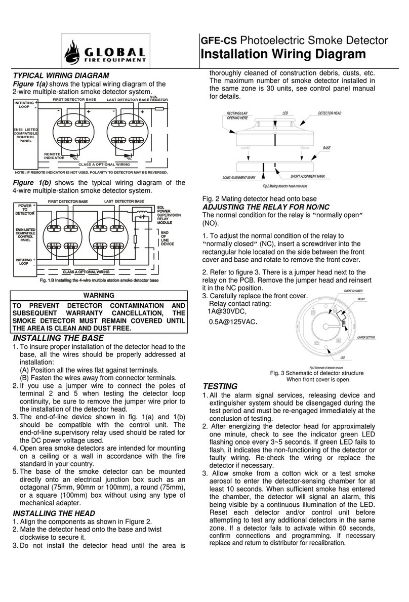
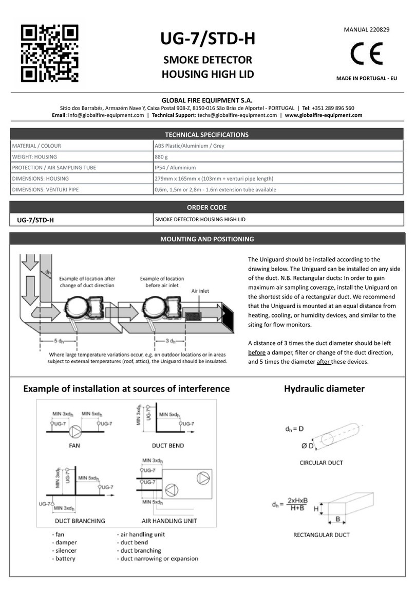
Global Fire Equipment UG-7/STD-H User manual

Global Fire Equipment

Global Fire Equipment UG-7/STD-H User manual

Global Fire Equipment GFE-CS Quick start guide

Global Fire Equipment

Global Fire Equipment GFE-CS Quick start guide

Popular Smoke Alarm manuals by other brands

Kidde 4899 user manual

Kidde

Kidde 4899 user manual

Ei Electronics Ei161e instruction manual

Ei Electronics

Ei Electronics Ei161e instruction manual

Honeywell SS4-AS Installation guide and operating manual

Honeywell

Honeywell SS4-AS Installation guide and operating manual

Firex PAT installation manual

Firex

Firex PAT installation manual

Arton SPD-3.4 user manual

Arton

Arton SPD-3.4 user manual

Thorn security MR300 Product application guide

Thorn security

Thorn security MR300 Product application guide

Alula RE614 quick start guide

Alula

Alula RE614 quick start guide

System Sensor 2100 Installation and maintenance instructions

System Sensor

System Sensor 2100 Installation and maintenance instructions

System Sensor BEAM200S Installation and maintenance instructions

System Sensor

System Sensor BEAM200S Installation and maintenance instructions

Honeywell NOTIFIER FSP-951T-SELFT Installation and maintenance instructions

Honeywell

Honeywell NOTIFIER FSP-951T-SELFT Installation and maintenance instructions

Alecto SA-110 manual

Alecto

Alecto SA-110 manual

Code one A owner's manual

Code one

Code one A owner's manual

INIM Electronics Air2-FD100 Installation and programming manual

INIM Electronics

INIM Electronics Air2-FD100 Installation and programming manual

Bosch FCS-320-TM Operation guide

Bosch

Bosch FCS-320-TM Operation guide

DSC WLS916-433 Series Installation and operating instructions

DSC

DSC WLS916-433 Series Installation and operating instructions

Smartwares SH8-90126 instruction manual

Smartwares

Smartwares SH8-90126 instruction manual

Aparton SPD-3.1M user manual

Aparton

Aparton SPD-3.1M user manual

Honeywell Home R200ST-N1 Installation and user guide

Honeywell Home

Honeywell Home R200ST-N1 Installation and user guide

manuals.online logo
manuals.online logoBrands
  • About & Mission
  • Contact us
  • Privacy Policy
  • Terms and Conditions

Copyright 2025 Manuals.Online. All Rights Reserved.