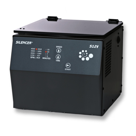
Global Focus Silencer JET Series User manual

JET
Series
Service ManualService Manual
Proudly designed and manufactured in the great United States

JET Service Manual v1.0 Revised: 01/01/2020
Copyright © 2020
Global Focus Marketing & Distribution, Ltd.
2280 Springlake # 106
Dallas, Texas 75234
800-323-4306
https://gfmd.com/support/
This manual contains confidential and proprietary information, and
is provided to Silencer®customers under license. Receipt of this
manual does not convey any rights to reproduce or disclose its
contents in any form. Global Focus Marketing & Distribution, Ltd.
(herein known as GFMD, Ltd) retains all rights to this manual and
its contents. Reproducing and/or disclosure of its contents is strictly
prohibited, and may violate Copyright and/or Patent laws.
While every effort has been made to ensure the completeness and
accuracy of this manual, Global Focus Marketing & Distribution,
Ltd. will not be liable for failure to follow standard safety
precautions.
Printed in the United States of America.

Table Of Contents
Chapter 1 Getting Started ............................................... 1-1
Scope.................................................................................... 1-1
Unpacking And Inspection.................................................... 1-1
Setup..................................................................................... 1-1
Rotor Installation.................................................................. 1-2
Chapter 2 About The JET................................................ 2-1
Purpose................................................................................. 2-1
Description ........................................................................... 2-1
Chapter 3 Using The JET................................................ 3-1
Orientation............................................................................ 3-1
Controls................................................................................ 3-1
Displays................................................................................ 3-1
Operation.............................................................................. 3-2
Operation Tips...................................................................... 3-2
Chapter 4 Cleaning ......................................................... 4-1
Chapter 5 Troubleshooting ............................................. 5-1
Status Codes ......................................................................... 5-1
Error Reset............................................................................ 5-1
Troubleshooting Table.......................................................... 5-1
Chapter 6 Functional Description ................................... 6-1
AC Power Distribution ......................................................... 6-1
DC Power Distribution ......................................................... 6-1
Operator Interface Circuits.................................................... 6-1
Lid Interlock Circuit ............................................................. 6-2
Lid Unlocking Circuit........................................................... 6-2
Tachometer Feedback Circuit ............................................... 6-2
Motor Control Circuit........................................................... 6-2
Motor Current Sense Circuit................................................. 6-3
Motor Drive Temperature Circuit ......................................... 6-3
Chapter 7 Technical Illustrations......................................7-1
Chapter 8 Parts Replacement Procedures.........................8-1
Precautions ........................................................................... 8-1
Equipment ............................................................................ 8-1
Motor.................................................................................... 8-1

Display/Control PCB............................................................ 8-2
Lidlock Assembly................................................................. 8-3
Chapter 9 Warranty ........................................................ 9-1
Appendix A Specifications ................................................ A-1
Performance Specifications...................................................A-1
Unit Specifications................................................................A-2
Appendix B Service Log ................................................... A-3
Appendix C Replacement Parts List ...................................A-4
Appendix D Lid Release Tool.............................................A-5

List of Illustrations
Figure 3.1 Control Panel Layout.......................................3-1
Figure 7.1 Wiring Diagram...............................................7-1
Figure 7.2 Display / Control PCB Schematic....................7-2
Figure 7.3 Display / Control PCB Layout.........................7-3
Figure 8.1 Front Panel Retaining Screws..........................8-2
Figure 8.2 Motor Gasket Removal....................................8-2

Chapter 1
Getting Started
JET Service Manual Page 1-1
SCOPE
This manual contains information with regards to application, installation, and operation of the
Silencer®JET table-top centrifuge, and must be read prior to setup or operation of the
centrifuge.
UNPACKING AND INSPECTION
Your new Silencer®centrifuge is packed in a specially designed shipping carton. Upon arrival
please check the condition of carton and note any damage. Keep all packing materials for the
warranty period of the centrifuge.
After unpacking your Silencer®carefully inspect it for damage. It is your responsibility to
report all damages to the transportation company and filing, if necessary, any damage claims.
At this point take a moment to ensure you have received the correct rotor, tube adapters, etc. If
not or if you have any questions regarding compatibility with your tubes, please contact GFMD,
Ltd. at 800-323-4306 before proceeding.
WARNING
Do not operate this equipment in a combustible
atmosphere!
SETUP
For your own safety and to prevent damage to the centrifuge, be sure to read this manual before
continuing with setup or operation of this centrifuge.
For smooth operation and long equipment life, choose a stable, level bench top.
Avoid sources of heat and/or moisture such as sinks, water baths, heating ducts, and direct
sunlight. A suitable environment is 20° to 25° C (68° to 77° F) with a relative humidity range of
30% to 60%. The minimum clearance is 6” on all sides. A cooler ventilated location and
leaving the lid open between cycles will allow longer and/or more frequent cycles without
overheating of samples. The maximum number of cycles that may be run consecutively will
depend upon operating speed, set time, ventilation around the centrifuge, and ambient
temperature. Samples that may be adversely affected by being warmed to 39°C during
centrifugation should be centrifuged in a refrigerated centrifuge such as the Silencer®TANK-R.
Plug the power cord into a properly grounded outlet and turn on main power interrupt (on back
of unit next to power cord). For safety, equipment life, and proper performance, your Silencer®
JET’s power requirements are 115V AC, 5 amperes, 60Hz. The power cord must be UL listed
or CSA certified, 18 AWG, and 6’ 7” or less in length.

Getting Started
JET Service Manual Page 1-2
WARNING
Operating the centrifuge without proper grounding can
cause dangerous electrical conditions and could result in
serious operator injury!
CAUTION Operation of centrifuge on an emergency power circuit
can cause damage to electronic circuits.
CAUTION Operation of centrifuge on a power strip increases
ground resistance and can cause damage to electronic
circuits.
ROTOR INSTALLATION
Insert the rotor onto the motor shaft ensuring the alignment pins in the motor shaft adapter fit
correctly into the alignment groove in the bottom of the rotor. The rotor must be installed
correctly for proper operation.
Replace the rotor securing hex screw. The screw must be securely tightened.

Chapter 2
About The JET
JET Service Manual Page 2-1
PURPOSE
The Silencer®JET is a quiet, general purpose centrifuge designed to be used to accelerate
sample separation through the application of relative centrifugal force (RCF). This product is
not intended to diagnose, treat, cure or prevent any disease.
DESCRIPTION
The direct drive system employs a powerful, specially designed, balanced, brushless motor
ensuring a smooth quiet operation spanning the full speed range of the instrument. This design
also promotes long bearing life and eliminates brush maintenance, thereby reducing operating
costs.
Excellent stability against imbalance is achieved due to special vibration absorbing drive
assembly mounts.
The operator and the JET are protected by several safety features:
•The centrifuge cannot be started with the lid open.
•The centrifuge will not run if the lidlock fails to securely lock.
•Once the rotor is in motion the lid cannot be opened until the rotor has stopped.
•The see-through high-strength lid allows the operator to view the rotor chamber without
opening the lid.
•The rotor chamber is strong and easy to clean.
For complete equipment specifications see Appendix A.

Chapter 3
Using The JET
JET Service Manual Page 3-1
O
RIENTATION
Take time now to acquaint yourself with the JET’s displays and controls. The basic operation is
very simple and the controls are mostly self-explanatory.
Figure 3.1
WARNING
Turning the power off does not remove power to the
centrifuge. Remove all power to the unit by unplugging
the power cord.
C
ONTROLS
START
If pressed when the unit is in the STANDBY mode, the START button will start the run
cycle.
Pressing the START button during a run cycle stops the cycle.
SPEED
Press the SPEED button to increment the speed to the desired RPM / RCF setting.
TIME
Press the TIME button to increment the time to the desired time setting.
D
ISPLAYS
RPM/RCF

Using
The
JET
JET Service Manual Page 3-2
There are four LEDs to indicate the selected speed. A blinking LED is an indication that
an error has occurred.
MINUTES
There are four LEDs to indicate the selected time in minutes. Blinking LEDs normally
indicates that the unit has reached set speed. If the RPM / RCF LED is also blinking an
error has occurred.
WARNING
Do not operate this equipment in a combustible
atmosphere!
O
PERATION
Chapter 1 must be read and the JET must be setup accordingly before continuing.
The set speed and time defaults to the last used speed and time setting. The settings can be
changed using the SPEED and TIME buttons.
Open the lid and load your samples, taking care to maintain a balanced load.
Close the lid and press the START button. The lidlock will engage, and the centrifuge will
accelerate to the set speed. Upon reaching the set speed the time LEDs will start blinking.
When the set time has elapsed the time LEDs will stop blinking and the centrifuge will
decelerate to a stop.
When the rotor has come to a complete stop the lidlock will release.
O
PERATION
T
IPS
•Do not drop or slam the lid!
•Use the emergency lid lock release only for emergencies.
•Only use the supplied emergency lid lock release tool.
•Unplug the centrifuge before using the emergency lid lock release tool.
•Leave the lid open between cycles.
If there are any questions regarding operation please contact GFMD, Ltd. at 800-323-4306.

Chapter 4
Cleaning
JET Service Manual Page 4-1
WARNING
Turning the power off does not remove power to the
centrifuge. Remove all power to the unit by unplugging
the power cord.
WARNING
Standard safety precautions for handling of biological
hazards must be followed!
CAUTION Do not get any liquids into the top of the motor. Many
disinfectants are extremely corrosive and may damage
the motor.
CAUTION Allowing liquid levels in the rotor chamber to rise to the
bottom of the motor seal may result in serious damage
to the centrifuge.
•The rotor must be removed from the centrifuge for disinfecting. The rotor can be disinfected
with PH neutral disinfectants if rinsed and dried prior to use. The disinfectant manufacturer’s
instructions must be followed. Do not use if the disinfectant manufacturer warns against use on
aluminum, stainless steel, or neoprene.
• Clean tube breakages and spills immediately and thoroughly. The interior can be disinfected
with PH neutral disinfectants. Disinfectants such as bleach can be used for the rotor chamber
only. The interior must be rinsed and dried thoroughly before using the centrifuge. Use water
sparingly when rinsing, as the motor seal is not watertight.
• Residue from broken tubes is highly abrasive. Operating the centrifuge with residue from
broken tubes can damage the finish on the accessories and rotor chamber possibly
compromising their protection from chemicals.
A white powder inside the rotor chamber is indicative of the debris from broken plastic tubes
not being thoroughly removed prior to operating.
A charcoal grey residue inside the rotor chamber is indicative of the debris from broken glass
tubes not being thoroughly removed prior to operating.
• The exterior should be kept clean with the use of a mild soap and a damp (not wet) lint-free
cloth. The centrifuge must be dried thoroughly before using.
CAUTION Use of disinfectants with PH >8 is not recommended.

Chapter 5
Troubleshooting
JET Service Manual Page 5-1
STATUS CODES
The numbering is based on counting up from the lowest RPM / MINUTES setting LED to the
highest. The RPM setting LED represents the most significant digit and the MINUTES setting
LED represents the least significant digit. The LEDs will blink to indicate an error has occurred.
This is a list of error codes and the brief description that the centrifuge displays when an error is
encountered. Check under symptoms for more details.
ERROR: 1.1 Check the lid safety interlock switch for proper alignment and continuity.
ERROR: 1.2 Check the lid safety interlock switch for proper alignment and continuity.
ERROR: 1.3 Do not attempt to open the lid until the unit has stopped.
ERROR: 2.1 Indicates no power is getting to the motor.
ERROR: 2.2 Indicative of a momentary drop or loss of line voltage.
ERROR: 2.3 Indicative of low line voltage or a momentary sag.
ERROR: 3.1 Indicates an over current error.
ERROR: 3.2 Motor Drive Hardware Fault
ERROR: 3.3 Motor Drive Transistor Over Temp
ERROR: 4.1 Over Speed
ERROR: 4.2 Under Speed
ERROR RESET
Pressing the front panel START button resets error messages.
TROUBLESHOOTING TABLE
The lid remains locked and the LEDs are not illuminated when
the main power switch is turned on.
POSSIBLE CAUSES POSSIBLE SOLUTIONS
No power to the JET. Ensure the JET is plugged in, and there
is power to the receptacle.
SYMPTOM
The fuses are blown. Replace the fuses with 5A, 250V, time
delay fuses. If the fuses blow again
contact GFMD, Ltd. at 800-323-4306
for assistance.

Troubleshooting
JET Service Manual Page 5-2
Will not start when the START button is pressed and “ERROR:
1.1” is displayed.
POSSIBLE CAUSES POSSIBLE SOLUTIONS
The lid safety interlock switch is
defective or misaligned. Check the lid safety interlock switch
for proper alignment and continuity.
Lid is not closed completely
preventing the lid from locking. Make sure the lid is completely closed.
Locking mechanism is mechanically
binding. Check for proper lid lock solenoid
movement.
SYMPTOM
Lid lock safety interlock switch is
defective or misaligned. Check the lid lock safety interlock
switch for proper alignment and
continuity.
Will not start when the START button is pressed and “ERROR:
2.1” is displayed.
POSSIBLE CAUSES POSSIBLE SOLUTIONS
Indicates no power is getting to motor. Ensure the motor wires are properly
connected to MOTA1, MOTB1, and
MOTC1 on the Power PCB.
The motor tachometer cable is
unplugged. Ensure the motor tachometer cable is
connected to MOTOR1 on the Power
PCB.
SYMPTOM
The power sagged so the unit did not
start before the bootstrap capacitors
discharged.
Check electrical outlet for stable line
voltage, and ensure that the circuit isn’t
overloaded.
Reset the unit by turning the main
power switch off for approximately 20
seconds and then back on.

Troubleshooting
JET Service Manual Page 5-3
Shuts down and a status code is displayed.
POSSIBLE CAUSES POSSIBLE SOLUTIONS
ERROR: 1.2 - Indicates the lid safety
interlock switch failed during a run
cycle or an attempt was made to open
the lid during the run cycle
If there was not an attempt to open the
lid before the unit came to a complete
stop, see suggestions for the centrifuge
not starting and giving an “ERROR:
1.1” error.
If someone attempted to open the lid
during the run cycle, please wait until
the unit has come to a complete stop
before opening the lid. Manually
releasing the lid during the cycle
creates a hazardous condition and is an
OSHA safety violation.
ERROR: 1.3 - Indicates the lid safety
interlock switch failed during
deceleration or an attempt was made
to open the lid before the unit came to
a complete stop.
If there was not an attempt to open the
lid before the unit came to a complete
stop, see suggestions for the centrifuge
not starting and giving an “ERROR:
1.1” error.
If someone attempted to open the lid
during the run cycle, please wait until
the unit has come to a complete stop
before opening the lid. Manually
releasing the lid during the cycle
creates a hazardous condition and is an
OSHA safety violation.
ERROR: 2.2 - Indicative of a
momentary drop in line voltage or loss
of line voltage.
Check for a loose power cord
connection to the outlet, an overloaded
circuit, or line voltage below 110 VAC.
ERROR: 2.3 - Indicative of low line
voltage or a momentary sag in line
voltage.
Check for a loose power cord
connection to the outlet, an overloaded
circuit, or line voltage below 110 VAC.
ERROR: 3.1 - Indicative of excess
motor current or a current spike. Ensure the plug to outlet connection is
secure and the unit is not plugged into a
power strip.
SYMPTOM
ERROR: 3.2 - Motor driver shutdown
due to current spike or driver
temperature.
Ensure the plug to outlet connection is
secure, the unit is not plugged into a
power strip, the vent fan is running, and
there is adequate space around the
centrifuge.

Troubleshooting
JET Service Manual Page 5-4
ERROR: 3.3 - The motor drive
MOSFETs are too warm. Ensure the vent fan is running and there
is adequate space around the
centrifuge.
ERROR: 4.1 - The speed is not stable
and exceeded the allowable maximum
speed.
Ensure the plug to outlet connection is
secure, the unit is not plugged into a
power strip, and the power circuit is not
overloaded.
ERROR: 4.2 - The speed is not stable
and dropped too low. Ensure the plug to outlet connection is
secure, the unit is not plugged into a
power strip, and the power circuit is not
overloaded.
The sample temperature is exceeding 39°C.
POSSIBLE CAUSES POSSIBLE SOLUTIONS
The rotor chamber heat extraction fan
isn’t running. Verify that the fan is running.
Cycle times are too long, operating
speed is too high, and /or cycles are
too frequent.
Lower the operating speed, shorten
spin time, and/or allow more cooling
time between cycles with the lid open.
Centrifuge is under a heat vent. Relocate the centrifuge away from heat
vents.
SYMPTOM
Centrifuge’s immediate ambient
environment is warm due to other
equipment.
Relocate unit away from heat
producing equipment.

Chapter 6
Functional Description
JET Service Manual Page 6-1
The JET consists of the following interactive circuits:
AC Power Distribution
DC Power Distribution
Operator Interface Circuits
Lid Interlock Circuit
Lid Unlocking Circuit
Tach Feedback Circuit
Motor Control Circuit
Motor Current Sense Circuit
Motor Drive Temperature Circuit
AC POWER DISTRIBUTION
Power for the JET is 115 VAC and is supplied through a CSA approved line cord with a three
prong grounding plug and power entry module which contains the 5 ampere fuses, and a double
pole power interrupt switch. The output of the power entry module is applied to the +24VDC
Power Supply and the vent fan.
DC POWER DISTRIBUTION
The output of the +24VDC Power Supply is applied to the Display / Control PCB. The positive
output goes to PLUS1 (VIN) and negative output goes to NEG1 (VSS). The common for all DC
power supplies is VSS.
VIN is applied to U4 pin 26, drain pin of Q3, Q5, & Q7, and pin 1 of the +5VDC regulator
(U3). Input of U3 is delayed by relay RX, R38, and R39 to give the +24VDC time to stabilize.
The output of U3 (VCC) is used for all logic circuits.
OPERATOR INTERFACE CIRCUITS
The Display / Control PCB handles setting and visual status of run activation, time, speed, and
displaying error messages.
The START push button switch is applied to U1 pin 17. The START button is used to start and
stop the run mode, and to reset errors.
The SPEED push button switch is applied to U1 pin 16. The SPEED button is used to increment
the speed selection.

Functional Description
JET Service Manual Page 6-2
The TIME push button switch is applied to U1 pin 15. The TIME button is used to increment
the time selection.
LID INTERLOCK CIRCUIT
The lidlock assembly has two switches wired in series. One indicates if the lid is open or closed
and the other indicates if the lock is engaged or disengaged. If either switch is open pin 1 of
LID1 will be high. This signal is applied to pin 23 of U1. This input is used to verify the
switches status prior to starting and to generate an error if either switch opens after the unit
starts. The default status assumes the lid is open in the event the lidlock assembly is unplugged
or there is a break in the circuit.
LID UNLOCKING CIRCUIT
The default condition of the lidlock assembly is locked. Unlocking of the lid is handled by
energizing a solenoid. Initially full voltage is applied to the solenoid to energize it. The
unlocking voltage is controlled from pin 24 of U1. This signal is applied to the gate of Q2 and
through C7 to pins 12 and 13 of U2. The output of U2 at pin 10 is applied to the gate of Q1. Q1
applies VSS to the solenoid.
After a time delay set by C7 and R28 the unlocking voltage turns off. The solenoid holding
voltage is supplied by Q2. Q2 applies VSS to the solenoid through the dropping resistors R24,
R25, R26, and R27.
TACH FEEDBACK CIRCUIT
There are three Hall Effect sensors in the motor. The sensor outputs are supplied to U4 on the
through HALL1. U4 uses this input to determine motor rotor position. The motor rotor position
information is used to control the three-phase motor driver U4. The output of one Hall Effect
sensor (HC) is also applied to U2 pins 1 and 2. The output of U2 at pin 4 (TAK) is supplied to
U1 pin10.
There are 4 TAK pulses per revolution so RPM can be calculated by measuring duration of a
tachometer pulse with an oscilloscope and applying the formula (((1/duration in
seconds)*60)/4). The speed can also be checked using a frequency counter and applying the
formula (((tachometer frequency in seconds)*60)/4).
MOTOR CONTROL CIRCUIT
When a run cycle is started a signal from pin 14 of U1 is applied to U4 pin 22 to enable the run
mode.
A PWM signal from U1 pin 10 is applied to pin 19 of U4. The PWM pulse is at a constant
frequency and a duty cycle that is adjusted based upon the TAK feedback to control motor
speed.

Functional Description
JET Service Manual Page 6-3
MOTOR CURRENT SENSE CIRCUIT
The voltage drop across R18, R19, R20 and R21 is proportional to the current through the drive
motor. This voltage is applied to U4 pin14. This is a negative feedback that counteracts the
PWM pulse to limit current draw of the motor. This voltage is also applied to ADC pin 22 of
U1 to supply current draw feedback. This feedback is used to control the PWM ramp during
acceleration.
MOTOR DRIVE TEMPERATURE CIRCUIT
The voltage drop across temperature sensor TH1 is applied to ADC pin 19 of U1 to supply
temperature feedback for the motor drive MOSFETs. If the temperature exceeds safe limits for
the MOSFETs the PWM drive is shutdown.


This manual suits for next models
3
Table of contents
Other Global Focus Laboratory Equipment manuals
Popular Laboratory Equipment manuals by other brands

Malvern Instruments
Malvern Instruments Zetasizer Nano Accessories guide

THORLABS
THORLABS LCC3111H user guide

crest Optics
crest Optics X-Light V2 TP Installation and user guide

Agilent Technologies
Agilent Technologies G2916A manual

Ocean Optics
Ocean Optics MonoScan-2000 user manual

Controls
Controls 15-D0410 instruction manual

Thermo Savant
Thermo Savant UVS400 instruction manual

Bio-Works
Bio-Works BabyBio S instructions

Thermo Scientific
Thermo Scientific RC 3BP Plus instruction manual

Leica
Leica CM3050 S Service manual

Clinispin Horizon
Clinispin Horizon 842STAT Operator's manual

Parker Research Corp
Parker Research Corp DA-1500 operating instructions