Global Gravity TubeLock User manual

02
17-01-2019
User manual TubeLock®
MJN
KSH
VCS
KSH
01
05-07-2016
User manual TubeLock®
MJN
KSH
VCS
KSH
Rev:
Date:
Description:
Prepared by:
Checked by:
QA Approval:
Final Approval:
Document no.:
Global Gravity –User manual
Global Gravity
TubeLock®
User manual
Responsible:
KSH
Global Gravity ApS ● Lillebæltsvej 37 ● DK 6715 Esbjerg N ● CVR: 33950705
www.globalgravity.dk

User manual
- 2 -
Global Gravity ApS ● Lillebæltsvej 37 ● DK 6715 Esbjerg N ● CVR: 33950705
Rev. 02
www.globalgravity.dk
Table of contents
1General information.............................................................................................................................................................................3
1.1 Introduction............................................................................................................................................................................................3
1.2 Purpose.................................................................................................................................................................................................3
1.3 Contact..................................................................................................................................................................................................3
2Personal protective equipment (recommended by Global Gravity).................................................................................................4
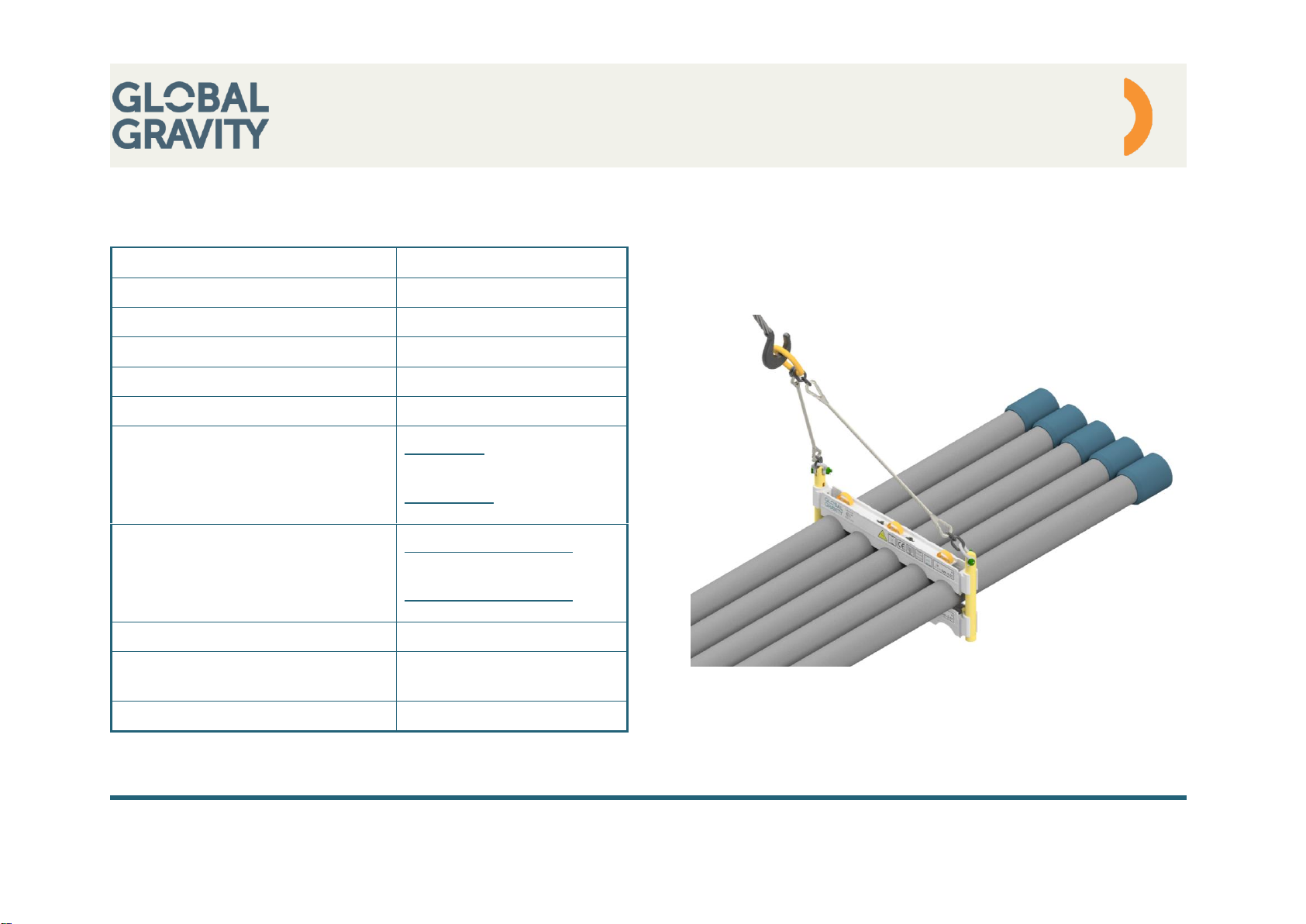
3System data .........................................................................................................................................................................................5
4Layout...................................................................................................................................................................................................6
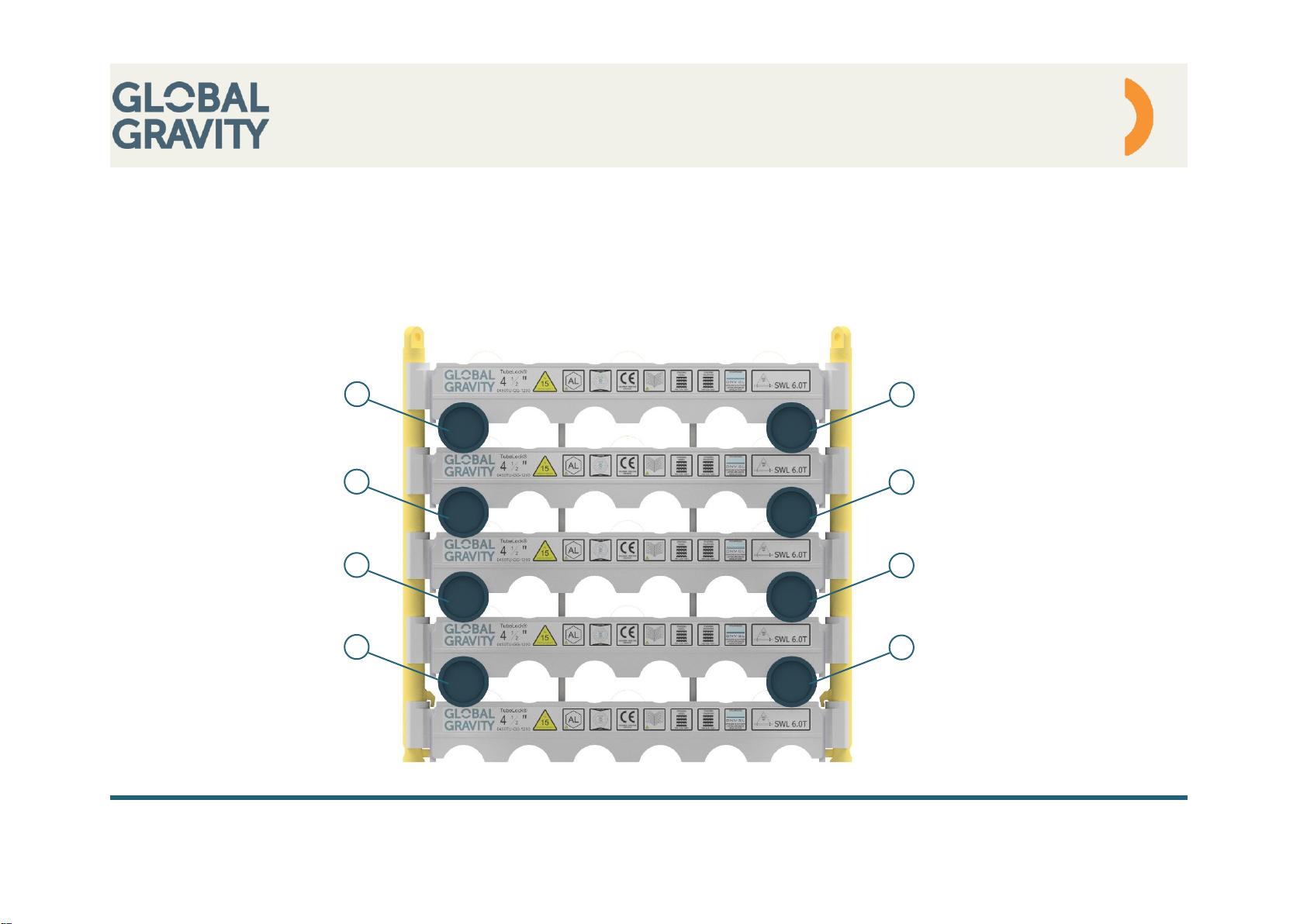
4.1 Package assembly.................................................................................................................................................................................6
4.2 Packing configuration –Empty spaces ..................................................................................................................................................7
4.3 Packing configuration –Different pipe length.........................................................................................................................................8
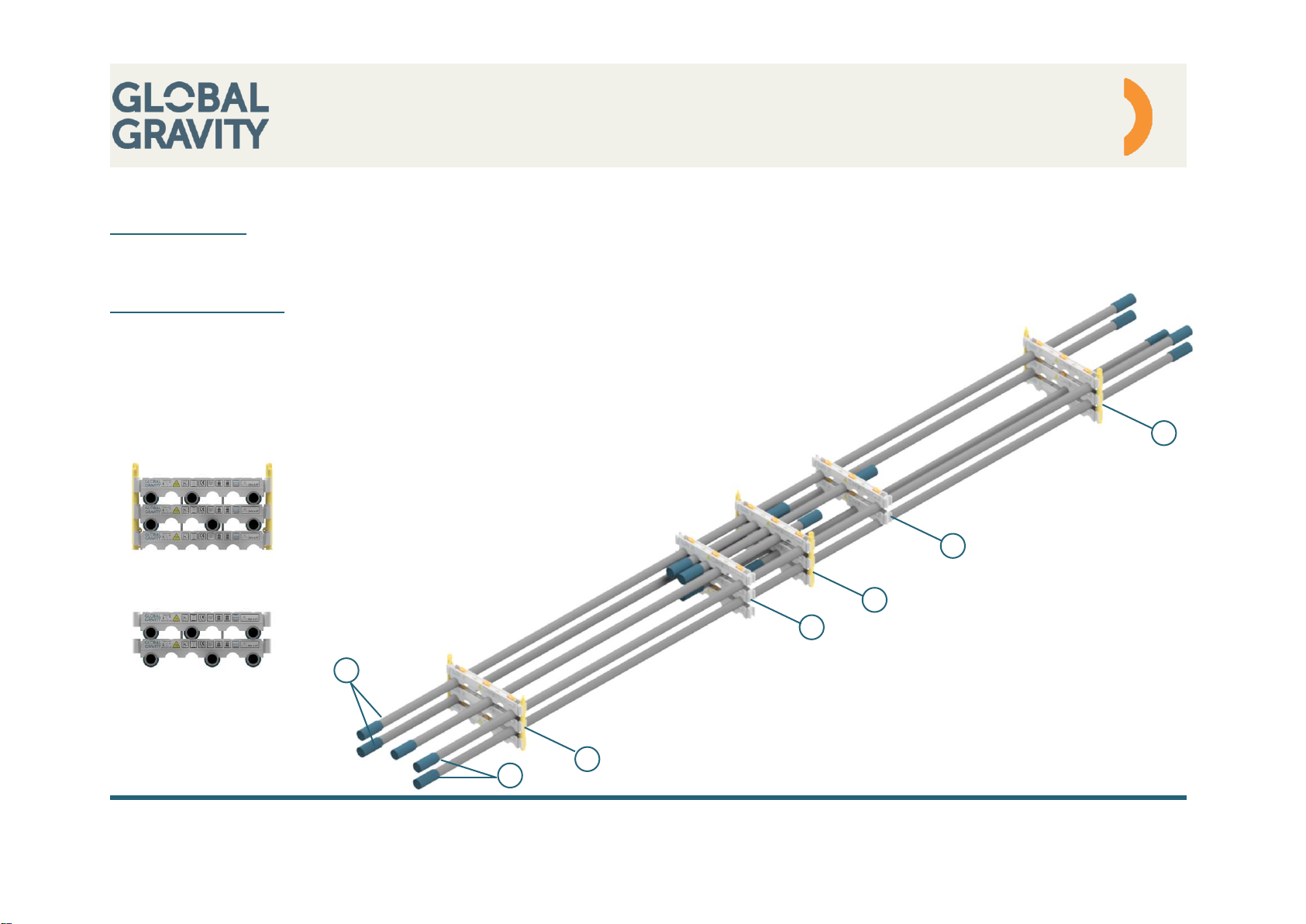
4.4 Exploded view .......................................................................................................................................................................................9
4.5 Component overview...........................................................................................................................................................................10
5Packing instruction ...........................................................................................................................................................................11
6Slings / Stacking................................................................................................................................................................................16
7Placing on the drilling rig..................................................................................................................................................................18
8Service................................................................................................................................................................................................21
9Handling.............................................................................................................................................................................................22

User manual
- 3 -
Global Gravity ApS ● Lillebæltsvej 37 ● DK 6715 Esbjerg N ● CVR: 33950705
Rev. 02
www.globalgravity.dk
1 General information
1.1 Introduction
TubeLock® is a transport, lifting and storage device designed for safe handling of drill pipes, casing and tubular normally called OCTG (Oil
Country Tubular Goods).
This system is designed for use with:
•Forklift
•Lorry
•Vessels
•Cranes
•Drilling rigs
1.2 Purpose
The purpose of instruction manual is to ensure that the TubeLock® will be assembled correctly and used in the right way for both lifting, storage
and general handling.
1.3 Contact
Global Gravity ApS
Lillebæltsvej 37
6715 Esbjerg N, Denmark
CVR 33950705
Main number: +45 71 99 20 10
Mail address: support@globalgravity.dk
Homepage: www.globalgravity.dk

User manual
- 4 -
Global Gravity ApS ● Lillebæltsvej 37 ● DK 6715 Esbjerg N ● CVR: 33950705
Rev. 02
www.globalgravity.dk
2 Personal protective equipment (recommended by Global Gravity)
Item:
Description:
PPE
01
Safety helmet during crane handling due to:
•Falling objects
•Personal hazards
•Mechanical hazards
02
According to local regulation
03
According to local regulation
04
Fall protection equipment when using TubeLock® in heights due to:
•Fall hazards
05
Safety shoes due to:
•Mechanical hazards
•Falling objects
•Personal hazards
06
Gloves due to:
•Personal hazards

User manual
- 5 -
Global Gravity ApS ● Lillebæltsvej 37 ● DK 6715 Esbjerg N ● CVR: 33950705
Rev. 02
www.globalgravity.dk
3 System data
Configuration
2⅜ - 14”
Tubing
Range 1-3
SWL
6,0 ton
Load test
2 x SWL
DNV certification
DNVGL-ST-0378
CE marked
Yes
Slings standard
Wire sling:
EN13414-1
Chain sling:
EN 818-4
Lifting poles
System with 3 frames:
3 left + 3 right / package
System with 4 frames:
4 left + 4 right / package
Shackles
Green pin 4,75 ton
Material
Profiles: Aluminum
Poles: Steel
Bolt tensioning (M 20)
150 Nm

User manual
- 6 -
Global Gravity ApS ● Lillebæltsvej 37 ● DK 6715 Esbjerg N ● CVR: 33950705
Rev. 02
www.globalgravity.dk
4 Layout
4.1 Package assembly
Standard assembly
Includes 3 sets of profiles
Optional assembly
Includes 4 sets of profiles

User manual
- 7 -
Global Gravity ApS ● Lillebæltsvej 37 ● DK 6715 Esbjerg N ● CVR: 33950705
Rev. 02
www.globalgravity.dk
4.2 Packing configuration –Empty spaces
There must always be at least one pipe in each side, per layer, in the position closest to lifting poles. Pipes A & B must be in full length, and go
through all the frames.
Pipe placement is applicable for all sizes and systems.
A
1
B
A
1
B
A
1
B
A
1
B

User manual
- 8 -
Global Gravity ApS ● Lillebæltsvej 37 ● DK 6715 Esbjerg N ● CVR: 33950705
Rev. 02
www.globalgravity.dk
4.3 Packing configuration –Different pipe length
Placement of pipe
Pipe A & B must be full length, and go through all frames. There must be as a minimum, of one pipe in each side per layer, in the position
closest to lifting poles
Securing of short pipes
Extra frames must be placed where it is necessary.
The weight of additional frames and pipes, must be placed even on both sides of centerline.
Lifting poles must be installed in frame assembly 1, but can be avodided in frame assembly 2
For further informations of special configurations, please contact Global Gravity for advise.
A
1
B
1
Frame assembly 1
Frame assembly 2
1
1
1
1
2
1
2
1
1

User manual
- 9 -
Global Gravity ApS ● Lillebæltsvej 37 ● DK 6715 Esbjerg N ● CVR: 33950705
Rev. 02
www.globalgravity.dk
4.4 Exploded view
Lifting pole - Left
Anchor lock
Sling
Lifting profile
M20 Bolts
Lifting pole - Right

User manual
- 10 -
Global Gravity ApS ● Lillebæltsvej 37 ● DK 6715 Esbjerg N ● CVR: 33950705
Rev. 02
www.globalgravity.dk
4.5 Component overview
The TubeLock® system comes in four different standard versions, from 1-layer models up to 4-layer models.
Right Lifting pole
Left Lifting pole
Lifting profile
M20 Bolt
Sling
System with
3 frames:
System with
4 frames:
System with
3 frames:
System with
4 frames:
System with
3 frames:
System with
4 frames:
System with
3 frames:
System with
4 frames:
System with
3 frames:
System with
4 frames:
1 Layer model
3
4
3
4
6
8
6
8
2
2
2 Layer model
3
4
3
4
9
12
12
16
2
2
3 Layer model
3
4
3
4
12
16
18
24
2
2
4 Layer model
3
4
3
4
15
20
24
32
2
2
5 Layer model
3
4
3
4
18
24
30
40
2
2

User manual
- 11 -
Global Gravity ApS ● Lillebæltsvej 37 ● DK 6715 Esbjerg N ● CVR: 33950705
Rev. 02
www.globalgravity.dk
5 Packing instruction
No.:
Description:
Sketch:
A-01
TubeLock® lifting profiles must be
located on a plan surface with a
distance between 7m and 9m
(between the two outermost profiles)
Alternatively, the system can be
assembled on a standard
TubeLock® assembly frame (Not
described in this instruction)
A-02
6 lifting poles must be installed (3 x
right and 3 x left) in the TubeLock®
lifting profile.
The lifting pole must be lowered
down in the lifting profile and turned
180 deg. In locked position
180˚

User manual
- 12 -
Global Gravity ApS ● Lillebæltsvej 37 ● DK 6715 Esbjerg N ● CVR: 33950705
Rev. 02
www.globalgravity.dk
No.:
Description:
Sketch:
A-05
Ensure that all threaded holes are in
activated position (2 holes for each
profile –Total 6 pcs.)
A-06
Tubular must be placed on the
TubeLock profiles
Ensure that the tubular is located
correct in the cutout.
Note!
The cantilevered part of the pipe
must be equal distributed in both
ends (approximately).
ACTIVATED POSITION
DEFAULT POSITION

User manual
- 13 -
Global Gravity ApS ● Lillebæltsvej 37 ● DK 6715 Esbjerg N ● CVR: 33950705
Rev. 02
www.globalgravity.dk
No.:
Description:
Sketch:
A-07
3 TubeLock profiles must be installed
on the top of the tubular.
A-08
6 assembling bolts must be mounted
between the bottom and the top
TubeLock profile.
The bolts must be tensioned to 150
Nm with a torque wrench.

User manual
- 14 -
Global Gravity ApS ● Lillebæltsvej 37 ● DK 6715 Esbjerg N ● CVR: 33950705
Rev. 02
www.globalgravity.dk
No.:
Description:
Sketch:
A-09
Anchor lock
1) Put the anchor lock through
the keyhole
2) Turn the anchor lock 90 deg.
3) Put the safety pin through
the hole in the anchor lock
and into the hole in the
TubeLock profile
4) The lifting pole is locked.
1
2
3
4

User manual
- 15 -
Global Gravity ApS ● Lillebæltsvej 37 ● DK 6715 Esbjerg N ● CVR: 33950705
Rev. 02
www.globalgravity.dk
No.:
Description:
Sketch:
A-11
Next layer of tubular can now be laid
out according to A-07 etc.
A-12
When the tubular is packed and
secured in one package, the tubular
is ready for stacking.
It is optional, if chain slings will be
fitted now or a later stage before
lifting.

User manual
- 16 -
Global Gravity ApS ● Lillebæltsvej 37 ● DK 6715 Esbjerg N ● CVR: 33950705
Rev. 02
www.globalgravity.dk
6 Slings / Stacking
No.:
Description:
Sketch:
B-01
When mounting slings:
Always use the most outer lifting
poles (Closest to the tubular ends).
Ensure that shackles are locked, and
pins are mounted.
Note!
Always mount the shackle so the nut
and safety split are to the inside of
frame.
B-02
A two-part crane sling must be
attached to the lifting eyes on the
lifting slings.
Min. sling angle is 60˚.
Min.
60˚

User manual
- 17 -
Global Gravity ApS ● Lillebæltsvej 37 ● DK 6715 Esbjerg N ● CVR: 33950705
Rev. 02
www.globalgravity.dk
No.:
Description:
Sketch:
B-03
Arranging sling during stacking.
1. The slings must be located to
the same side (as shown on
sketch).
2. The next package can be
stacked with the slings
located to the other side (as
shown on sketch).
3. The next package can be
stacked with the slings
located to the same side a
package 1 (as shown on
sketch).
Maximum stacking height and
weight is as following
Note: Whichever comes first
If weight of tubular is unknown, each
TubeLock® package is to be calculated as 6T.
2
3
1

User manual
- 18 -
Global Gravity ApS ● Lillebæltsvej 37 ● DK 6715 Esbjerg N ● CVR: 33950705
Rev. 02
www.globalgravity.dk
A
7 Placing on the drilling rig
No.:
Description:
Sketch:
C-01
Side view:
Stacking of TubeLock® system seen
from the side.
The principle is to offset each
package.
Once placed the first layer, the next
layer must be offset to the side and
hereafter back again.
C-02
Top view:
When placing the packages on the
rig.
Packages must be placed as shown
on sketch, to get the benefit of
shifting tubular from package to
package.
IMPORTANT!
See explanation of detail A –Next
Page

User manual
- 19 -
Global Gravity ApS ● Lillebæltsvej 37 ● DK 6715 Esbjerg N ● CVR: 33950705
Rev. 02
www.globalgravity.dk
No.:
Description:
Sketch:
C-03
Packages must be placed with a
distance of 5mm between the
“thumb” at the lifting pole and the
next pipe.
This distance makes it possible for
free movement of lifting poles and to
ensure that the package can be
stacked with the earlier explained
method.
C-04
It’s important to place the first layer of
packages correctly.
When unlocking the lifting poles,
attention must be given to the
distance explained in C-03.
It is recommended using the
TubeLock® spacer to insure the right
placing.
5 mm
Thumb
mm

User manual
- 20 -
Global Gravity ApS ● Lillebæltsvej 37 ● DK 6715 Esbjerg N ● CVR: 33950705
Rev. 02
www.globalgravity.dk
No.:
Description:
Sketch:
C-05
Once the packages are set according
to above recommendations, it is
possible to walk on top of the tubular
and start to dismantle the packages,
working from the top down.
Remove sling and shackles.
Loosen all bolts and remove them.
Remove TubeLock® profiles.
Note!
Offshore; slings to be removed from
each layer, before next layer is
installed
Table of contents
Popular Industrial Equipment manuals by other brands

ARCA
ARCA 827S.E Series operating manual

Zimmer
Zimmer GEH8000 Series Installation and operating instructions

STAUFF
STAUFF RH Series Translation of the original operating manual

Bosch
Bosch T10296 Original instructions

Texas Automation Products
Texas Automation Products DES-30 manual

Siemens
Siemens 6EP1331-2BA10 operating instructions