Global Hobby Sporty EP A. R. F. User manual

1
INSTRUCTIONS FOR FINAL ASSEMBLY
The Wattage Sporty EP isdistributed exclusively by Global Hobby Distributors 18480 Bandilier Circle, Fountain Valley, CA 92728
All contents copyright © 2000, Global Hobby Distributors Version V1.0 11/00
Thank you for choosing the Wattage Sporty EP as your next project. The Sporty EP is a small electric-
powered sport airplane built specifically to be flown in large parks or fields. The Sporty EP can be assembled
in three different configurations. If you want a docile Sunday-Flyer, assemble the Sporty EP as a three
channel airplane featuring elevator, rudder and throttle control. If you want your Sporty EP a little more
"snappy", assemble it with elevator, aileron and throttle control. If you want to fly your Sporty EP like a
full size aerobat, assemble it with elevator, aileron, throttle and rudder control. We even offer an
upgraded 370 size motor that will make your Sporty EP even more fun!
Features such as a molded foam fuselage, molded foam wing panels and molded foam flying surfaces
add up to make a lightweight, yet durable structure that is very easy to repair in the event of a mishap. And
because it is light weight, performance using the included 280 size motor and gear box is excellent. The
airplane is quite fast, yet is very stable throughout the entire speed range, making it a perfect choice for
both the experienced pilot and for those just graduating from their first or second airplane.
When you open the box, you will notice that you won't have much left to do or to purchase to finish your
new airplane. In addition to the usual nuts and bolts, the Sporty EP includes a 280 size motor with gear
box, a propeller, threaded wire pushrods with clevises and control horns, a prebent landing gear wire with
plastic lightweight wheels, a plastic molded cowling and a colorful decal sheet. The kit also includes the
necessary hardware to convert the Sporty EP to aileron control.
We hope you enjoy your new Wattage Sporty EP as much as we have enjoyed designing and building it
for you. If you have any questions or comments, please feel free to contact us. We have also included a
product survey in the back of this manual. After you have finished assembling the Sporty EP, please take
a moment to fill it out and send it to us. We enjoy hearing any comments or suggestions that you may have.

2
TABLE OF CONTENTS
SAFETY WARNING
This R/C airplane is not a toy! If misused, it can cause serious bodily injury and/or damage to property. Fly only in open
areas and preferably at a dedicated R/C flying site. We suggest having a qualified instructor carefully inspect your
airplane before its first flight. Please carefully read and follow all instructions included with this airplane, your radio
control system and electronic speed control.
Cowling ........................................................................12
Trimming the Cowling........................................... 12
Mounting the Cowling........................................... 12
Radio Installation ......................................................... 13
Installing the Servos ..............................................13
Installing the Control Horns ..................................13
Installing the Pushrods...........................................13
Final Assembly............................................................. 14
Installing the Receiver ...........................................14
Installing the ESC ..................................................15
Installing the Battery Tray ..................................... 15
Installing the Flight Battery ................................... 16
Applying the Decals .............................................. 16
Balancing...................................................................... 16
Balancing the Sporty EP........................................ 16
Control Throws ............................................................ 16
Flying the Sporty EP ....................................................17
Glossary of Terms ........................................................ 17
Aileron Conversion ......................................................18
Joining the Wing Panels ........................................ 18
Installing the Torque Rods..................................... 18
Applying the Wing Reinforcement........................ 19
Installing the Aileron Servo................................... 20
Installing the Aileron Linkage............................... 20
Elevator Servo.............................................................. 21
Installing the Elevator Servo .................................21
Product Evaluation Sheet............................................. 23
Safety Warning ...............................................................2
Our Recommendations...................................................3
Radio Control System..............................................3
Electronic Speed Control.........................................4
Flight Battery ...........................................................4
Battery Charger ........................................................4
Sporty EP Setup Information .........................................4
Additional Items Required .............................................5
Tools and Supplies Required .........................................5
Kit Contents....................................................................6
Metric Conversion Chart................................................6
Wing Assembly ..............................................................7
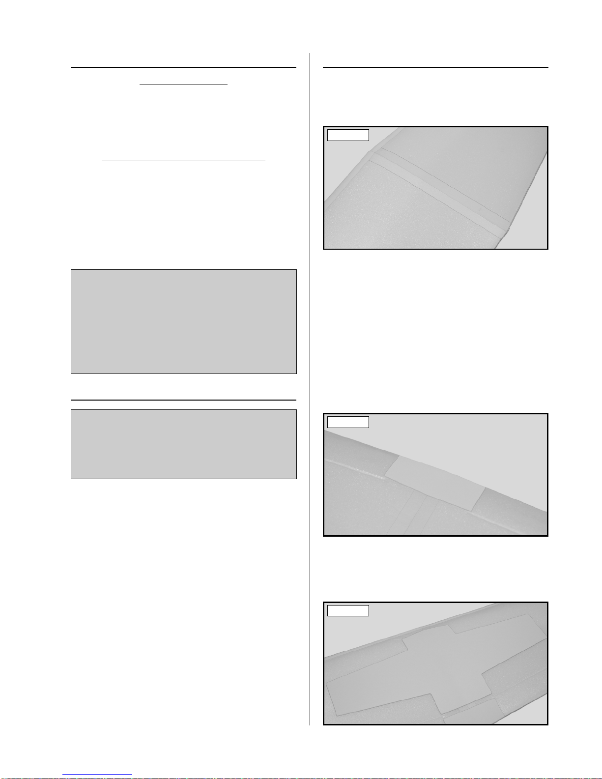
Joining the Wing Panels ..........................................7
Applying the Wing Reinforcement..........................7
Wing Mounting ..............................................................8
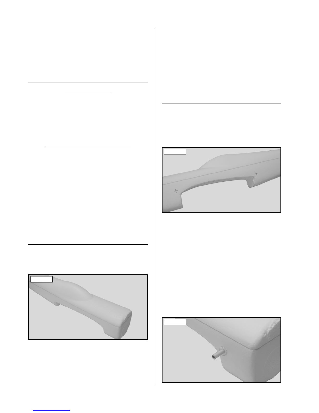
Joining the Fuselage Halves ..........................................8
Installing the Wing Tubes........................................8
Mounting the Wing ..................................................9
Tail Surfaces ...................................................................9
Aligning the Horizontal Stabilizer ..........................9
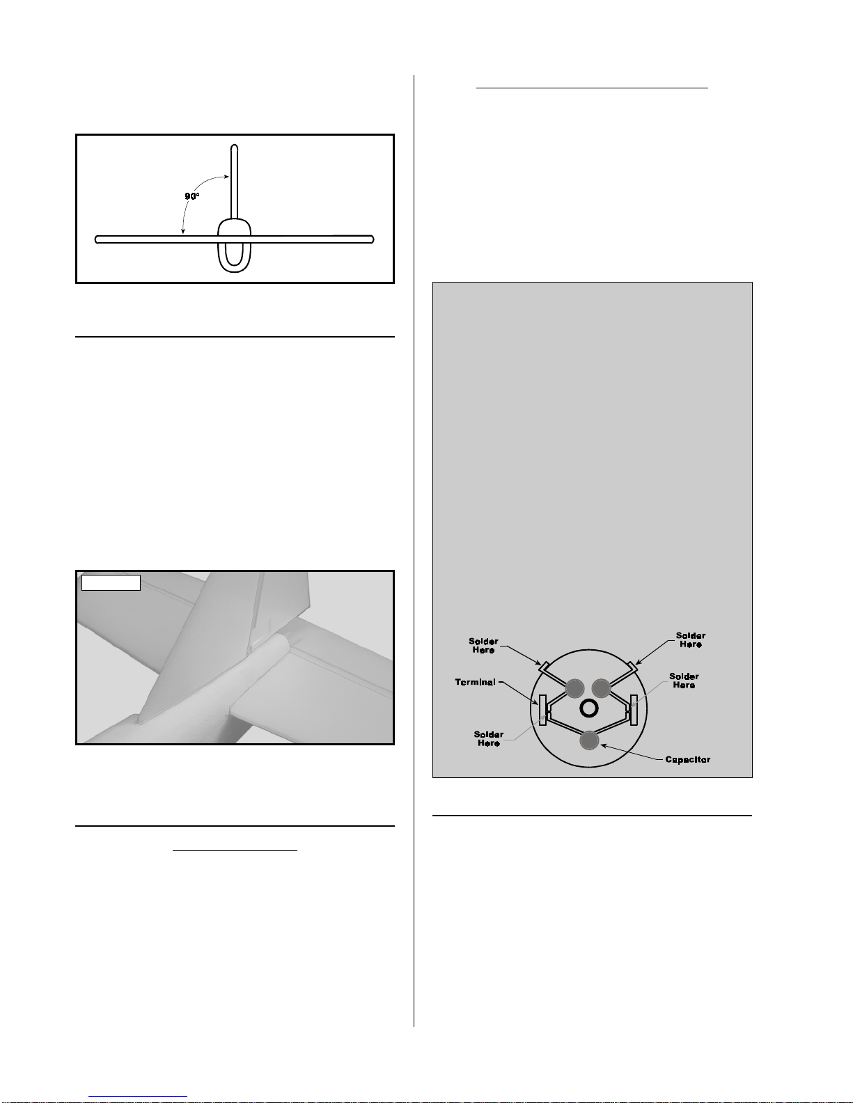
Mounting the Horizontal Stabilizer .........................9
Aligning the Vertical Stabilizer ...............................9
Mounting the Vertical Stabilizer............................10
Motor Installation.........................................................10
Installing the Gear Box Plate.................................10
Assembling the Gear Box......................................11
Installing the Gear Box Assembly.........................11
Landing Gear................................................................11
Installing the Wheels .............................................11
Installing the Tail Skid ...........................................12

3
This instruction manual is designed to guide you through the entire final assembly process of your new Wattage
Sporty EP in the least amount of time possible. Along the way you'll learn how to properly assemble your new
airplane and also learn assembly tips that will help you in the future. We have listed some of our recommendations
below. Please read through them before going any further.
The Sporty EP is constructed of a combination of EEP and Closed Cell foam. It is very important
that you use no solvents, Cyanoacrylate (C/A) glue, or paint that can damage foam. If any of
these chemicals comes in contact with the foam parts, the parts will be destroyed and will not
be covered under warranty. Use only epoxy where glue is required. If you decide to paint the
Sporty EP, use a paint that will not attack foam and always test on a scrap piece first.
✔Please read through each step before starting as-
sembly. You should find the layout very complete and
simple. Our goal is to guide you through assembly
without any of the headaches and hassles you might
expect.
✔There are check boxes next to each step. After you
complete a step, check off the box. This will help you
keep from losing your place.
✔Cover your work table with brown paper or a soft
cloth, both to protect the table and to protect the indi-
vidual parts.
✔Keep a couple of small bowls or jars handy to put
the small parts in after you open the accessory bags.
✔We have included a glossary of terms beginning
on page # 17. Check it out if you come across a term
that is unfamiliar to you.
✔We're all excited to get a new airplane in the air,
but take your time. This will ensure you build a straight,
strong and great flying airplane.
✔If you come across this symbol ☛, it means that
this is an important point or an assembly hint.
If you should find a part missing or damaged, or have any questions about assembly, please
contact us at the address below:
Wattage Customer Care
18480 Bandilier Circle
Fountain Valley CA 92728
Phone: (714) 963-0329 Fax: (714) 964-6236 E-mail: service@globalhobby.net
The following section describes our general recommendations to help you in deciding which types of accessories to
purchase for your new Wattage Sporty EP. We have tested all of these items with the airplane and found that these
products will offer the best in performance, reliability and economy. We have also provided a more complete list on page
# 4 that shows the different ways the Sporty EP can be assembled to suit your flying style and experience.
OUR RECOMMENDATIONS
The Sporty EP will require a minimum 3 channel radio control system with two micro servos. The radio system we
recommend using is the Hitec Focus 3 AM radio with 2 HS-81 Micro servos. This radio system includes two micro
servos, a three channel mini receiver, servo mounting hardware and a setup guide.
If you want to purchase a radio system that will be more upgradeable in the future, a four or more channel radio with
two micro servos and a mini or micro receiver will work well. If you decide to go this way, our recommendation would
be to use the Hitec Flash 4X Glider FM Computer radio with 2 HS-81 Micro servos. This is a very good radio system
that offers the capacity to grow as your experience grows.
If you already have a standard sized radio system, you will need to purchase an after-market mini or micro receiver and
two micro servos. If you need to purchase these items we recommend using the Hitec Micro 555 receiver (P/N 759118)
and two Cirrus CS-21 Micro servos.
RADIO CONTROL SYSTEM
Our Recommendations Cont.8

4
To operate the motor, we suggest using a proportional electronic speed control (ESC) that features battery eliminator
circuitry (BEC) and auto-cutoff. BEC allows you to eliminate the receiver battery and uses the flight battery to control
both the motor and the radio system. Eliminating the receiver battery provides a great weight savings which effectively
increases performance. The auto-cutoff feature turns off the motor when the voltage in the battery drops too low to
operate the radio system safely. This guarantees safe operation throughout the entire flight. To obtain these features, we
suggest using the Wattage IC-5A ESC. This ESC is very small and light, which will result in an overall increase in the
performance of the airplane.
The battery you choose should be a 6 cell (7.2Volt) or 7 cell (8.4Volt) 270Mah Nickel Cadmium (NiCD) battery pack or
a 6 cell to 8 cell 650Mah Nickel Metal Hydride (NiMH) battery pack. The 7 cell and 8 cell battery packs will provide
more power, resulting in higher speed and better climb-out, but they weigh more than the 6 cell battery pack. The Nickel
Metal Hydride battery packs will give you about 25% longer run-time, but not quite as much overall power.
ELECTRONIC SPEED CONTROL
FLIGHT BATTERY
Because the flight battery is small and it powers both the motor and the radio system, we suggest using an Automatic Delta
Peak Charger such as the Promax Activator Digital Peak Charger to charge the flight battery. It is vital to the Sporty EP's
flying performance that the battery pack be fully charged every flight, so using a peak charger is very important.
BATTERY CHARGER
The Sporty EP can be assembled in three different configurations to suit your flying style and experience. Listed below
are the different configurations complete with our recommendations for each one. This instruction manual details the
assembly of each of these three configurations.
Configuration # 1 for Docile Sunday Flying
This configuration would be for those pilots who have just graduated from learning to fly a basic trainer, or for those
who want a very docile Sunday-Flyer. Assemble the Sporty EP using the stock motor and gear box. Use two Cirrus
CS-21 Micro servos (P/N 444227) for elevator and rudder control and assemble the wing with the stock amount of
dihedral. Use the Wattage IC-5A ESC (P/N 128482) and a 6 cell 270Mah NiCD battery pack (P/N 128516).
Configuration # 2 for More "Snappy" Flight Characteristics
This setup would be for those pilots who want a more aerobatic sport flyer. Assemble the Sporty EP using the stock
motor and gear box. Use two Cirrus CS-21 servos (P/N 444227) for elevator and aileron control and assemble the wing
with no dihedral. Use the Wattage IC-5A ESC (P/N 128482) and a 7 cell 270Mah NiCD battery pack (P/N 128517) or
an 8 cell 650Mah NiMH battery pack (P/N 128528).
Configuration # 3 for "Full-House" Aerobatics
This setup would be for those pilots who want a full-house aerobatic flyer. Assemble the Sporty EP using the
upgraded 370 size motor and gear box. Use three Cirrus CS-10 servos (P/N 444052) for elevator, rudder and aileron
control and assemble the wing with no dihedral. Use the Wattage IC-5A ESC (P/N 128482) and an 8 cell 650Mah
NiMH battery pack (P/N 128528).
Note
An after-market Wattage 370 size motor (P/N 131350) is available separately. It can be purchased and installed in place
of the stock 280 size motor in any of the configurations shown above. This more powerful motor will increase the
performance of the Sporty EP and is only recommended for more experienced pilots.
Sporty EP Setup Information

5
ADDITIONAL ITEMS REQUIRED
❑{1} Hitec Focus 3 AM Micro Radio System
❑{1} Trinity AA Batteries - 8 Pack # 837801
❑{1} Wattage IC-5A ESC # 128482
❑{1} Wattage 6C 270Mah NiCD Battery # 128516
❑{1} Promax Activator Digital Charger # 885650
❑{1} Heavy Duty Clear Scotch®Tape # 105
OPTIONAL ITEMS
TOOLS AND SUPPLIES REQUIRED
❑Kwik Bond 5 Minute Epoxy # 887560
❑# 0 Phillips Head Screwdriver
❑# 1 Phillips Head Screwdriver
❑Excel Modeling Knife # 692801
❑Adjustable Wrench
❑Needle Nose Pliers
❑Wire Cutters
❑Magnum Z-Bend Pliers # 237473
❑Electric or Hand Drill
❑1/16" Drill Bit
❑3/16" Drill Bit
❑Straight Edge Ruler
❑{1} Hitec Flash 4X FM Micro Radio System
❑{3} Cirrus CS-10 Super Micro Servos # 444052
❑{1} Wattage 7C 270Mah NiMH Battery # 128517
❑{1} Wattage 8C 650Mah NiMH Battery # 128528
❑{1} Wattage 370 Size Motor # 131350
❑{1} Wattage Male 2-Pin Micro Plug # 131162
❑Builder's Triangle
❑220 Grit Sandpaper w/Sanding Block
❑Pen or Pencil
❑Scissors
❑Masking Tape
❑Rubbing Alcohol
❑Paper Towels
❑NHP Epoxy Mixing Sticks # 864204
❑NHP Epoxy Mixing Cups # 864205
❑Soldering Iron
❑Solder
If you decide to purchase the upgraded 370 size motor you will also need to purchase three capacitors to use as noise
suppressors. These will prevent the electric motor from causing receiver interference. Also, since the motor does not
come prewired with connectors, you will need to purchase a Wattage male 2-pin micro plug as listed above. This plug
will come with sufficient wire to solder to the motor.
The heavy duty Scotch®tape can be purchased in any drug store or supermarket. You don't have to use Scotch brand;
however, because it helps strengthen the wing, it's important that the tape have a high tensile strength. The 3M/Scotch®
part number is 105.
To make your modeling experience totally enjoyable, we recommend that you get experienced, knowledgeable help
with assembly and during your first flights. Your local hobby shop has information about flying clubs in your area
whose membership includes qualified instructors. We also recommend that you contact the AMA at the address below.
They will be able to help you locate a flying field in your area also.
Academy of Model Aeronautics
5151 East Memorial Drive
Muncie IN 47302-9252
(800) 435-9262
www.modelaircraft.org
Wattage guarantees this kit to be free from defects in both material and workmanship, at the date of purchase. This does not cover
any component parts damaged by use, misuse or modification. In no case shall Wattage's liability exceed the original cost of
the purchased kit.
In that Wattage has no control over the final assembly or material used for final assembly, no liability shall be assumed for any
damage resulting from the use by the user of the final user-assembled product. By the act of using the final user-assembled
product, the user accepts all resulting liability.

6
KIT CONTENTS
We have organized the parts as they come out of the box for easier identification during assembly. Before you begin
assembly, group the parts like we list them. This will ensure that you have all of the parts before you begin assembly and
it will also help you become familiar with each part.
If you find a part missing or damaged please call us at 1-714-962-0329 or send us an email at service@globalhobby.com
AIRFRAME ASSEMBLIES
❑{1} Molded Foam Fuselage Top
❑{1} Molded Foam Fuselage Bottom
❑{1} Right Wing Panel
❑{1} Left Wing Panel
❑{1} Horizontal Stabilizer w/Elevator
❑{1} Vertical Stabilizer w/Rudder
❑{1} Molded Plastic Cowling
❑{1} Molded Plastic Battery Tray
MOTOR & GEAR BOX ASSEMBLY
❑{1} 280 Size Motor w/Pinion Gear
❑{1} Molded Gear Box Front w/Bushings
❑{1} Molded Gear Box Back
❑{1} Molded Gear Box Mounting Plate
❑{1} 7.5 x 5 Nylon Propeller
❑{1} Propeller Shaft w/Nylon Gear
❑{2} 3mm Hex Nuts
❑{2} 2.5mm x 9mm Wood Screws
❑{4} 3mm x 10mm Self-Tapping Screws
❑{1} Spinner Assembly
CONTROL ASSEMBLIES
❑{2} 1.5mm x 400mm Threaded Pushrod Wires
❑{2} Nylon Control Horns w/Backplates
❑{2} Nylon Clevises
❑{2} 1mm x 100mm Pushrod Wires w/Z-Bends
❑{2} Prebent Aileron Torque Rods
❑{1} Aileron Reinforcement Board
MISCELLANEOUS ITEMS
LANDING GEAR ASSEMBLY
❑{1} Prebent Landing Gear Wire
❑{2} Molded Plastic Wheels
❑{2} Molded Plastic Wheel Retainers
❑{1} Molded Plastic Tail Skid
❑{1} 4mm x 70mm Aluminum Tube
❑{1} 4mm x 80mm Aluminum Tube
❑{4} 4mm Nylon Sleeves
❑{1} Wing Center Section Reinforcement Board
❑{1} Wing Trailing Edge Reinforcement Board
❑{4} Rubber Bands
❑{1} Double Sided Tape
❑{1} Molded Plastic Switch Plate
❑{1} Decal Sheet
METRIC CONVERSION CHART
To convert inches into millimeters: Inches x 25.4 = mm
1/64" = .4mm
1/32" = .8mm
1/16" = 1.6mm
3/32" = 2.4mm
1/8" = 3.2mm
5/32" = 4.0mm
3/16" = 4.8mm
1/4" = 6.4mm
3/8" = 9.5mm
1/2" = 12.7mm
5/8" = 15.9mm
3/4" = 19.0mm
1" = 25.4mm
2" = 50.8mm
3" = 76.2mm
6" = 152.4mm
12" = 304.8mm
18" = 457.2mm
21" = 533.4mm
24" = 609.6mm
30" = 762.0mm
36" = 914.4mm

7
WING ASSEMBLY
TOOLS AND SUPPLIES REQUIRED
❑Kwik Bond 5 Minute Epoxy
❑220 Grit Sandpaper w/Sanding Block
❑Scissors
❑Rubbing Alcohol
❑Paper Towels
❑NHP Epoxy Mixing Sticks
❑NHP Epoxy Mixing Cups
ITEMS REQUIRED
❑{1} Right Wing Panel
❑{1} Left Wing Panel
❑{1} Wing Center Section Reinforcement Board
❑{1} Wing Trailing Edge Reinforcement Board Photo # 1
❑5) Using the same technique, apply one strip of
Scotch®tape over the centersectionjoint on top of thewing.
❑6) Apply one long strip of Scotch®tape to the bot-
tom of the wing. Apply the tape down the middle of the
wing, perpendicular to the centerline joint, from wing tip
to wing tip.
❑7) Carefully fold the wing trailing edge reinforce-
ment board in half lengthwise. Remove it from its
protective backing and carefully adhere the reinforcement
board over the trailing edge of the wing at the center sec-
tion. See photo # 2 below.
Photo # 2
❑8) Remove the wing center section reinforcement
board from its protective backing. Carefully adhere the
reinforcement board to the top of the wing, making sure
that it's centered over the wing's center section. See
photo # 3 below.
Photo # 3
JOINING THE WING PANELS
❑1) Test fit the two wing panels together. They
should fit together with few or no gaps between the two,
and the leading edges and trailing edges should line up
evenly.
☛If the wing panels don't fit together properly, care-
fully sand the root ends of each wing panel straight using
220 grit sandpaper with a sanding block. Be careful not
to change the dihedral angle.
❑2) Mix a generous amount of Kwik Bond 5 Minute
Epoxy. Apply a thin layer to the ends of both wing pan-
els, making sure that you cover all of the gluing surfaces.
❑3) Fit the wing panels back together and realign
them. Remove any excess epoxy using a paper towel and
rubbing alcohol. Hold the wing panels together firmly
until the epoxy sets up - about 10 minutes.
☛If you are assembling the wing with ailerons please
turn to page # 18 and follow steps # 1 - # 19 under the
section "Aileron Conversion". If you are assembling
the wing without ailerons please follow the steps be-
low.
APPLYING THE WING REINFORCEMENT
❑4) After the epoxy has fully cured, apply a strip of
Scotch®tape to the bottom of the wing, over the center
section joint, from the leading edge to the trailing edge.
See photo # 1 below.
If you are assembling the Sporty EP with ailerons, you
will also need the following items:
❑{2} Prebent Aileron Torque Rods
❑{1} Aileron Reinforcement Board
❑Straight Edge Ruler
❑Pen or Pencil

8
☛Because the tape and the reinforcement board add a
lot of strength to the wing, it is important that they all be
pressed firmly in place.
❑9) Using a pair of scissors, carefully trim the back
edge of the trailing edge reinforcement board flush with
the trailing edge of the wing.
WING MOUNTING
❑Kwik Bond 5 Minute Epoxy
❑Excel Modeling Knife
❑3/16" Drill Bit
❑Straight Edge Ruler
❑220 Grit Sandpaper w/Sanding Block
❑Pen or Pencil
❑Masking Tape
❑Rubbing Alcohol
❑Paper Towels
❑NHP Epoxy Mixing Sticks
❑NHP Epoxy Mixing Cups
ITEMS REQUIRED
❑{1} Molded Foam Fuselage Top
❑{1} Molded Foam Fuselage Bottom
❑{1} 4mm x 70mm Aluminum Tube
❑{1} 4mm x 80mm Aluminum Tube
❑{4} Nylon Sleeves
❑{4} Rubber Bands
TOOLS AND SUPPLIES REQUIRED
JOINING THE FUSELAGE HALVES
❑1) Test fit the top and bottom fuselage halves to-
gether. They should fit together with few or no gaps
between the two, and the outside edges of each half should
line up evenly. See photo # 4 below.
Photo # 4
☛If the fuselage halves don't fit together properly, care-
fully remove any irregularities using 220 grit sandpaper
with a sanding block.
❑2) Mix a generous amount of Kwik Bond 5 Minute
Epoxy. Apply a thin layer to the gluing surfaces of both
fuselage halves.
❑3) Fit the fuselage halves back together and realign
them. Remove any excess epoxy using a paper towel and
rubbing alcohol and use several small pieces of masking
tape to hold the fuselage halves firmly together until the
epoxy fully cures.
❑4) After the epoxy has cured, remove the masking
tape and carefully sand the seam between the two fuse-
lage halves smooth using 220 grit sandpaper with a
sanding block.
INSTALLING THE WING TUBES
❑5) Using a ruler and a pencil, measure and mark the
locations of the four wing tube mounting holes. Two holes
(one on each side) are located 1/4" in front of the wing
saddle and 1/4" above it. Two holes (one on each side)
are located 1/4" in back of the wing saddle and 1/4" above
it. See photo # 5 below.
Photo # 5
❑6) Using a 3/16" drill bit, carefully drill one hole
through the fuselage sides at each of the marks you drew.
☛To prevent tearing up the foam, don't drill the holes
using an electric drill. It is better to use your hand to
slowly twist the drill bit.
❑7) Using 220 grit sandpaper, carefully roughen the
surface of both aluminum tubes and the outer surface of
all four nylon sleeves. This will help the epoxy adhere
better to the parts when you glue them into place.
❑8) Push one nylon sleeve into each of the four holes.
Slide the 4mm x 80mm aluminum tube through the two
front holes and slide the 4mm x 70mm aluminum tube
through the two rear holes. See photo # 6 below.
Photo # 6

9
❑9) Mix a small amount of Kwik Bond 5 Minute
Epoxy. Center both of the aluminum tubes and glue them
into place by applying a small dab of epoxy to the tube
and sleeve where they meet the fuselage sides. Apply the
epoxy from inside the fuselage and allow the epoxy to
fully cure before proceeding.
MOUNTING THE WING
❑10) Place the wing into the wing saddle, aligning
the centerline of the wing with the centerline of the fuse-
lage. Hold the wing securely in place using four rubber
bands - two per side.
TAIL SURFACES
TOOLS AND SUPPLIES REQUIRED
❑Kwik Bond 5 Minute Epoxy
❑Straight Edge Ruler
❑Builder's Triangle
❑220 Grit Sandpaper w/Sanding Block
❑Pen or Pencil
❑Masking Tape
❑Rubbing Alcohol
❑Paper Towels
❑NHP Epoxy Mixing Sticks
❑NHP Epoxy Mixing Cups
ITEMS REQUIRED
❑{1} Horizontal Stabilizer w/Elevator
❑{1} Vertical Stabilizer w/Rudder
ALIGNING THE
HORIZONTAL STABILIZER
❑1) Slide the horizontal stabilizer into place in the
fuselage. To align the stabilizer push it forward until the
back edge of the stabilizer is even with the back edge of
the fuselage and adjust the stabilizer side-to-side, align-
ing the outer edges of the stabilizer mounting area with
the outer edges of the fuselage. See photo # 7 below.
Photo # 7
Figure # 1
A=A-1
❑2) With the wing mounted to the fuselage and the
stabilizer aligned, look carefully from the front of the fu-
selage at both the wing and the stabilizer. When aligned
properly, the stabilizer should be level with the wing. If it
is not level, use 220 grit sandpaper with a sanding block
to adjust the height of the fuselage mounting sides until
the correct alignment is achieved. See figure # 1 below.
❑3) Now check to make sure that the tips of the sta-
bilizer are equal distances from the tips of the wing. Use
a ruler and measure from one wing tip to the stabilizer tip
on the same side. Do this for both sides. When the stabi-
lizer is aligned properly, both of these measurements
should be the same. See figure # 2 below.
Figure # 2
B=B-1
❑4) When satisfied with the alignment, use a pencil
to draw a couple of alignment marks on the top and bot-
tom of the stabilizer where it meets the fuselage sides.
❑5) Remove the stabilizer from the fuselage. Mix a
generous amount of Kwik Bond 5 Minute Epoxy. Apply
a thin layer of epoxy to the top and bottom gluing sur-
faces on the horizontal stabilizer and to the gluing surfaces
on the fuselage.
❑6) Slide the stabilizer back into place and realign it
with the alignment marks you drew. Remove any excess
epoxy using a paper towel and rubbing alcohol and use
several pieces of masking tape to hold the stabilizer se-
curely in place until the epoxy fully cures.
MOUNTING THE
HORIZONTAL STABILIZER
ALIGNING THE
VERTICAL STABILIZER
❑7) Push the vertical stabilizer down firmly into the
molded slot in the top of the fuselage.

10
❑8) While holding the vertical stabilizer in place, use
a builder's triangle to check and ensure that it is aligned
90º to the horizontal stabilizer. See figure # 3 below.
Figure # 3
MOUNTING THE
VERTICAL STABILIZER
❑9) When satisfied with the alignment, remove the
stabilizer from the fuselage. Mix a generous amount of
Kwik Bond 5 Minute Epoxy. Apply a thin layer of epoxy
to the gluing surfaces on the vertical stabilizer and to the
mounting slot in the fuselage.
❑10) Push the stabilizer firmly into place and realign
it, double checking that it is 90º to the horizontal stabi-
lizer. Remove any excess epoxy using a paper towel and
rubbing alcohol and use several pieces of masking tape to
hold the stabilizer securely in place until the epoxy fully
cures. See photo # 8 below.
Photo # 8
❑11) After the epoxy has fully cured remove the
masking tape.
MOTOR INSTALLATION
TOOLS AND SUPPLIES REQUIRED
❑Kwik Bond 5 Minute Epoxy
❑# 1 Phillips Head Screwdriver
❑Excel Modeling Knife
❑220 Grit Sandpaper w/Sanding Block
❑Masking Tape
❑Rubbing Alcohol
❑Paper Towels
❑NHP Epoxy Mixing Sticks
❑NHP Epoxy Mixing Cups
ITEMS REQUIRED
❑{1} 280 Size Motor w/Pinion Gear
❑{1} Molded Gear Box Front w/Bushings
❑{1} Molded Gear Box Back
❑{1} Molded Gear Box Mounting Plate
❑{1} Propeller Shaft w/Nylon Gear
❑{2} 2.5mm x 9mm Wood Screws
❑{4} 3mm x 10mm Self-Tapping Screws
❑{1} Prebent Landing Gear Wire
INSTALLING THE GEAR BOX PLATE
❑1) Using 220 grit sandpaper with a sanding block,
carefully sand the front of the fuselage smooth and straight.
❑2) Test fit the gear box mounting plate onto the front
of the fuselage. To properly align the mounting plate, the
outer edges of the plate should line up with the outer edges
of the fuselage.
❑3) When satisfied with the alignment, remove the
plate from the fuselage. Mix a generous amount of Kwik
Bond 5 Minute Epoxy and apply a generous layer to only
the front of the fuselage.
If you are assembling the Sporty EP with the upgraded
370 size motor, you will need to remove the brass pin-
ion gear from the stock motor and install it onto the
new motor.
The pinion gear can be easily removed by first heating
it using a lighter or mini-torch, then carefully pushing
it off using a flat blade screwdriver. To install the pin-
ion gear on the new motor, first heat it then push it onto
the motor shaft. Allow the pinion gear to cool, then
check to ensure it is secure.
☛You may have to drill out the pinion gear to match
the diameter of the motor shaft.
☛To prevent radio interference caused by the elec-
tric motor, you need to solder three capacitors to the
back of the motor. One capacitor should be soldered
between each motor terminal and the motor can. The
third capacitor should be soldered between the two
motor terminals. See figure # 4 below.

11
Photo # 9
❑4) Set the gear box mounting plate back into place
and realign it. Push the plate firmly into place and re-
move any excess epoxy using a paper towel and rubbing
alcohol. Use several pieces of masking tape to hold the
gear box plate securely in place until the epoxy fully cures.
See photo # 9 below.
ASSEMBLING THE GEAR BOX
❑5) Slide the propeller shaft through the two prein-
stalled bushings in the front gear box half and push it
forward until the nylon gear is up against the back of the
gear box.
❑6) Slide the motor into place, making sure that the
pinion gear engages the nylon gear on the propeller shaft.
❑7) Slide the back half of the gear box over the back
of the motor and use two 2.5mm x 9mm sheet metal screws
and one 3mm x 10mm self tapping screw to secure the
two halves together. The two sheet metal screws should
be installed in the two lower mounting holes and the self
tapping screw should be installed in the upper mounting
hole. See photo # 10 below.
Photo # 10
☛It is normal for there to be front-to-back play in the
propeller shaft. This will go away after installing the pro-
peller and spinner assembly.
❑8) Mix a small amount of Kwik Bond 5 Minute
Epoxy. Apply a small dab of epoxy to the side of the
motor, where it meets the back gear box half. Allow the
epoxy to cure before proceeding.
☛The epoxy will prevent the motor from turning inside
the gear box.
❑9) Using a modeling knife, carefully cut away the
foam from inside the hole in the middle of the gear box
mounting plate.
❑10) Carefully press the landing gear wire into the
molded groove in the back of the gear box assembly. See
photo # 11 below.
INSTALLING THE GEAR BOX ASSEMBLY
Photo # 11
❑11) Mount the gear box assembly to the mounting
plate using three 3mm x 10mm self-tapping screws.
Tighten the screws firmly to hold the assembly in place.
See photo # 12 below.
Photo # 12
LANDING GEAR
TOOLS AND SUPPLIES REQUIRED
❑Kwik Bond 5 Minute Epoxy
❑Rubbing Alcohol
❑Paper Towels
❑NHP Epoxy Mixing Sticks
❑NHP Epoxy Mixing Cups
ITEMS REQUIRED
❑{2} Molded Plastic Wheels
❑{2} Molded Plastic Wheel Retainers
❑{1} Molded Plastic Tail Skid
INSTALLING THE WHEELS
❑1) Push one plastic wheel retainer into the molded
hole in the center of each plastic wheel. Push one wheel
retainer/wheel assembly firmly onto the end of each axle.

12
INSTALLING THE TAIL SKID
❑2) Test fit the plastic tail skid onto the bottom of the
fuselage. When aligned properly, the back edge of the
tail skid should be even with the back edge of the fuse-
lage. The tail skid should also be centered in the middle
of the fuselage. See photo # 13 below.
Photo # 13
❑3) When satisfied with the alignment, remove the
tail skid. Mix a small amount of Kwik Bond 5 Minute
Epoxy and apply a thin layer to the bottom of the tail
skid. Push the tail skid back into place and realign it.
Remove any excess epoxy using a paper towel and rub-
bing alcohol and hold the tail skid in place until the epoxy
sets up - about 10 minutes.
COWLING
TOOLS AND SUPPLIES REQUIRED
❑Excel Modeling Knife
❑Adjustable Wrench
❑220 Grit Sandpaper w/Sanding Block
❑Scissors
ITEMS REQUIRED
❑{1} Molded Plastic Cowling
❑{1} 7.5 x 5 Nylon Propeller
❑{2} 3mm Hex Nuts
❑{1} Spinner Assembly
TRIMMING THE COWLING
❑1) Using a pair of scissors, carefully cut off the
molded radius along the back edge of the cowling, being
careful to keep the back edge of the cowl straight.
❑2) Using 220 grit sandpaper with a sanding block,
carefully sand the back edge of the cowling smooth and
straight.
❑3) Using a modeling knife, cut out the molded
circle and the molded air-intake on the front of the cowl-
ing. Cut out the molded landing gear recess on the bottom
of the cowling, too. See photo # 14 at top right.
❑4) Slide the cowling over the gear box assembly and
onto the fuselage.
❑5) Thread one 3mm hex nut onto the propeller shaft
and tighten it until it will not thread on any further.
❑6) Slide the propeller onto the propeller shaft,
making sure that the back of the propeller slides firmly
over the hex nut.
☛The back of the propeller is molded to fit over the
hex nut.
❑7) Slide the rear half of the spinner assembly onto
the propeller shaft and up against the propeller. Install
and tighten the second 3mm hex nut to hold the assem-
bly in place. See photo # 15 below.
MOUNTING THE COWLING
Photo # 15
❑8) Firmly press the spinner cone into the rear half
of the spinner assembly until it snaps into place.
☛When necessary, the spinner cone can be removed
using a small flat blade screwdriver.
❑9) Adjust the cowling so that the spinner ring is even
with the edges of the spinner . When satisfied with that
alignment, push the cowling back until there is a 1/16"
gap between the front of the cowling and the back of the
spinner.
❑10) When satisfied with the alignment, use Scotch®
tape to hold the cowling securely in place.
Photo # 14

13
RADIO INSTALLATION
ITEMS REQUIRED
❑{2} 1.5mm x 400mm Threaded Pushrod Wires
❑{2} Nylon Control Horns w/Backplates
❑{2} Nylon Clevises
❑{1} Double Sided Tape
TOOLS AND SUPPLIES REQUIRED
❑# 0 Phillips Head Screwdriver
❑Excel Modeling Knife
❑Needle Nose Pliers
❑Wire Cutters
❑Magnum Z-Bend Pliers
❑Electric or Hand Drill
❑1/16" Drill Bit
❑3/16" Drill Bit
❑Straight Edge Ruler
❑Pen or Pencil
If you are assembling the Sporty EP with ailerons, you
will need the following items also:
❑{2} 1mm x 100mm Pushrod Wires w/Z-Bends
INSTALLING THE SERVOS
☛Ifyouare assembling the Sporty EPwithaileron con-
trol please turn to page # 20 and follow steps # 20 - # 32
to install the aileron servo and pushrods.
☛If you are assembling the Sporty EP without rud-
der control please turn to page # 21 and follow steps
# 1 - # 4 to install the elevator servo.
☛If you are assembling the Sporty EP with rudder
and elevator control, please follow the steps below.
Photo # 16
INSTALLING THE CONTROL HORNS
❑5) Using a modeling knife, cut one thin slot through
the middle of each molded recess in both the elevator and
the rudder. Cut the slot large enough for the ends of the
control horns to pass through.
❑6) Push one control horn through each slot. The
end of the elevator control horn should be on the bottom
of the elevator and the end of the rudder control horn
should be on the right side of the rudder.
❑7) Making sure the flat portion of the backplates
face away from the control surfaces, push the backplates
over the ends of the control horns until you hear them
"click" into place. See photo # 17 below.
☛The servos should be installed toward the back of the
molded cutout, with both servo output shafts facing the
back of the fuselage.
❑4) Remove the protective backing from the top of
the double sided tape. To install the servos, hold both
servos tightly together and carefully push them down into
the molded cutout. Push both servos down firmly to se-
cure them to the servo tape. See photo # 16 below.
Photo # 17
INSTALLING THE PUSHRODS
❑8) Using a 3/16" drill bit, carefully drill the rudder
pushrod exit hole through the back of the molded fairing
in the top of the fuselage.
☛Don't push the backplates too far down over the con-
trol horns or you will crush the foam.
❑1) The elevator and rudder servos are installed side-
by-side in the molded cutout in the back of the servo
compartment. Depending on the size of the servos you're
using you may need to widen the cutout to accommodate
them. If this is necessary, use a modeling knife to re-
move equal amounts of foam from each side of the cutout.
☛Do not widen the cutout any wider than necessary
for the servos to fit tightly. This will prevent you from
cutting through the top of the canopy area and will ensure
that the servos are installed firmly.
❑2) Using a modeling knife, cut a piece of double
sided tape to the dimension of 3/4" x 1-5/8".
❑3) Remove the protective backing from one side of
the tape and carefully stick the tape to the bottom of the
molded servo cutout in the fuselage.

14
❑9) Plug the elevator and rudder servos into the re-
ceiver. Plug the ESC into the receiver and the flight
battery into the ESC . Turn on the radio system and cen-
ter both of the servos using the trim levers on the
transmitter.
❑10) Thread one nylon clevis onto each of the two
1mm x 400mm threaded pushrod wires. Thread the
clevises on far enough to leave room for adjustments later.
❑11) Slide one of the pushrod wires up through the
back of the fuselage, making sure that the wire enters the
servo compartment above the servos. Snap the clevis into
the elevator control horn. See photo # 18 below.
Photo # 18
❑12) Place a "single arm" servo horn onto the eleva-
tor servo, making sure that the servo horn is centered and
points toward the fuselage side. The arm should have at
least three holes in it.
❑13) With both the servo horn and the elevator cen-
tered, use a pen and draw a mark on the pushrod wire
where it crosses the third hole out from the center of the
servo horn.
❑14) Unsnap the clevis and remove the pushrod wire
from the fuselage. Using Magnum Z-Bend Pliers, make a
Z-Bend in the pushrod wire at the mark you drew. Use
wire cutters to remove the excess wire.
❑15) Slide the pushrod wire back into place and snap
the clevis into the control horn. Attach the servo horn to
the Z-Bend, then attach the servo horn to the servo, mak-
ing sure it's centered. Install and tighten the servo horn
retaining screw, provided with your servo, to secure the
servo horn into place. See photo # 19 below.
Photo # 19
☛You will have to enlarge the hole in the servo arm
using a 1/16" drill bit, so that the pushrod wire will fit
through; and, depending on the length of the servo horn,
you may have to cut it shorter so that it doesn't hit the side
of the fuselage.
❑16) Install the rudder pushrod wire using the same
technique as with the elevator pushrod wire. The Z-Bend
should be installed into the third hole out from the center
of the servo horn as well. See photo # 20 below.
Photo # 20
FINAL ASSEMBLY
TOOLS AND SUPPLIES REQUIRED
❑Kwik Bond 5 Minute Epoxy
❑Excel Modeling Knife
❑Straight Edge Ruler
❑220 Grit Sandpaper w/Sanding Block
❑Pen or Pencil
❑Scissors
❑Masking Tape
❑Rubbing Alcohol
❑Paper Towels
❑NHP Epoxy Mixing Sticks
❑NHP Epoxy Mixing Cups
ITEMS REQUIRED
❑{1} Molded Plastic Battery Tray
❑{4} Rubber Bands
❑{1} Decal Sheet
❑{1} Molded Plastic Switch Plate
❑1) Mount the receiver into the molded cutout in front
of the servos using a small piece of double sided tape. If
you are using a different size receiver than what's included
with the Focus 3 AM radio system, you may need to cut
away some of the foam so that the receiver will fit.
☛Orientate the receiver so that the antenna exits toward
the front of the airplane.
INSTALLING THE RECEIVER

15
Photo # 21
❑2) Uncoil the receiver antenna and feed it out
through the elevator pushrod exit hole in the back of the
fuselage. Use a couple of pieces of Scotch®tape to hold
the antenna in place. See photo # 21 below.
☛If you have assembled the Sporty EP with ailerons
you will need to mount the receiver in the molded cutout
in the front of the airplane. Depending on the size of the
receiver, you may need to enlarge the cutout so that the
receiver will fit properly. This will ensure the receiver
does not interfere with the aileron linkage when the wing
is installed. See photo # 22 below.
INSTALLING THE ESC
Photo # 22
❑3) Connect the motor leads from the ESC to the
motor leads from the motor. Install the throttle lead into
the proper slot in the receiver.
❑4) Mount the ESC to the fuselage floor, behind the
firewall. Use a small piece of double sided tape to hold it
in place. See photo # 23 below.
Photo # 23
☛If you are using an ESC other than the Wattage IC-5A
youmayneedtomodifytheconnecteronthe motor to match
the connector on your ESC.
☛When you turn on the motor the propeller should turn
counter-clockwise. If it does not, switch the polarity of
the motor connectors. Under no circumstances should
you switch the polarity of the battery leads.
❑5) If the ESC you're using has an on-off switch
and/or an arming switch, they can both be mounted using
the plastic switch mounting plate. Install the plate into
the molded recess in the bottom of the fuselage using Kwik
Bond 5 Minute Epoxy. See photo # 24 below.
Photo # 24
❑6) After the epoxy has fully cured, mount the on-off
switch and the arming switch to the plastic plate using the
hardware provided with your ESC.
INSTALLING THE BATTERY TRAY
❑7) Using a modeling knife, carefullycut out theplas-
tic battery tray along its outer edges. Use 220 grit
sandpaper with a sanding block to sand the edges straight
and smooth. See photo # 25 below.
Photo # 25
❑8) Install the wing onto the fuselage using two rub-
ber bands - one per side. Set the battery tray over the
center of the wing and align it with the fuselage. Tempo-
rarily hold the tray in place by sliding the mounting flanges
under the rubber bands. See photo # 26 below.
Photo # 26

16
❑9) Carefully align the battery tray with the fuse-
lage. When satisfied with the alignment, use a pencil to
draw several marks on the bottom of the wing to locate
the final position of the tray.
❑10) Remove the battery tray. Using 220 grit sand-
paper, lightlyroughen the bottom surface of each mounting
flange.
❑11) Mix a small amount of Kwik Bond 5 Minute
Epoxy. Apply a thin layer of epoxy to the bottom of both
mounting flanges. Set the battery tray back into place
and realign it. Remove any excess epoxy using a paper
towel and rubbing alcohol and use two rubber bands to
hold the tray in place until the epoxy fully cures.
INSTALLING THE FLIGHT BATTERY
❑12) Set the flight battery into the battery tray. Use
the remaining two rubber bands to secure both the wing
and the flight battery in place. See photo # 27 below.
Photo # 27
☛The location of the flight battery shown above is only
approximate. You may need to move it fore or aft to bal-
ance the airplane when that is done in the next section.
APPLYING THE DECALS
❑13) Using a clean cloth, wipe the airframe down
completely to remove any dust and debris.
❑14) Working with one decal at a time, use a pair of
scissors and carefully cut out the decal along its outer
edges.
❑15) Remove the protective backing from the decal
and stick the decal to the airplane (use the box cover pho-
tos to position the decals). Lightly rub the decal with a
soft cloth to remove any trapped air from beneath it.
☛If any air bubbles form in the decal you can "prick"
the bubble with a straight pin to release the air.
❑16) Repeat the steps above to install the remaining
decals. Rub each decal down thoroughly to adhere them
into place.
BALANCING
TOOLS AND SUPPLIES REQUIRED
❑Straight Edge Ruler
❑Masking Tape
BALANCING THE SPORTY EP
❑1) It is critical that your airplane be balanced cor-
rectly. Improper balance will cause your airplane to lose
control and crash.
This location is recommended for initial test flying. The
C.G. can be moved aft up to 1/4", but it is not recom-
mended that the C.G. be located any farther back than
1-7/8" behind the leading edge of the wing.
☛The Sporty EP should be balanced with the flight bat-
tery mounted in the battery tray.
❑2) Install the wing onto the fuselage and the flight
battery into the battery tray. Place two short pieces of
masking tape on the top of the wing, 1-5/8" back from the
leading edge, at the fuselage sides.
❑3) Turn the airplane upside down and place your
fingers on the masking tape and carefully lift the air-
plane. If the nose of the airplane falls, the airplane is
nose heavy. To correct this, move the flight battery back
just far enough to bring the airplane into balance. If the
tail of the airplane falls, the airplane is tail heavy. To
correct this, move the flight battery forward only enough
to bring the airplane into balance. When balanced cor-
rectly, the airplane should sit level or slightly nose down
when you lift it up with your fingers.
☛Once you have flown and become familiar with the
flight characteristics of the Sporty EP, the balance point
(C.G.) can be moved aft up to 1/4" to change the flight
performance. Moving the balance point back will cause
the airplane to be more responsive, but less stable. Do
not fly the Sporty EP beyond the recommended bal-
ance range or an uncontrollable crash could result!
The Center of Gravity is located 1-5/8"
back from the leading edge of the wing,
at the fuselage sides.
CONTROL THROWS
❑1) We recommend setting up the Sporty EP using
the control throws listed on the next page. We list control
throw recommendations for both test flying and sport fly-
ing. Use the test flying settings for your initial flights.

17
TEST FLYING
Elevator: 3/16 up 3/16 down
Rudder: 1/2 right 1/2 left
Aileron: 3/16" up 3/16" down
❑3) You can increase or decrease the control throws
by moving the pushrod wires in or out from the center of
the servo arm. Moving the pushrod wires out will in-
crease the control throws. Moving the pushrod wires in
will decrease the control throws.
☛It is highly recommended that you do not use any
more elevator control throw than what is recommended.
Because the Sporty EP is a short coupled airplane, it is
very sensitive to elevator control input. More elevator
input than recommended can cause the Sporty EP to
snap-roll and crash.
❑2) After you have become familiar with the flying
characteristics of the Sporty EP, you may want to increase
the control throws to the settings listed below.
SPORT FLYING
Elevator: 1/4 up 1/4 down
Rudder: 3/4 right 3/4 left
Aileron: 5/16" up 5/16" down
The Sporty EP is a gentle flyer; however, because of
its speed, it is not recommended for the beginning flier.
The Sporty EP can either be taken off from the ground
(R.O.G.) or it can be hand-launched. We don't recom-
mend R.O.G. takeoffs if you've assembled the Sporty EP
without rudder control.
Takeoffs from the ground should only be done from
a smooth surface. Apply full power and slowly feed in
right rudder to keep the airplane tracking straight. Once
sufficient airspeed has been reached, gently apply up el-
evator to lift the airplane off the ground. Climb out straight
ahead in a shallow climb to build up speed. Do not make
any steep turns right after take off or you may stall the
airplane.
To hand-launch the Sporty EP, gently grasp the bat-
tery tray between your thumb and forefinger at the C.G.
location. Hold the airplane above shoulder level and turn
on the motor to full power. With the motor running at full
power, gently toss the Sporty EP straight ahead. Do not
throw it up at an angle. Let the airplane fly straight and
level to pick up airspeed, then climb up to your desired
altitude. Be careful not to climb too steeply after hand-
launching or the airplane could stall.
In the air, the Sporty EP flies as gently or as aggres-
sively as you want it to. Set up with rudder and elevator
control, the Sporty EP flies like a low wing sport trainer.
Set up with aileron, rudder and elevator, the Sporty EP
flies like a seasoned aerobatic park-flyer. You can expect
flight times ranging from 5 - 10 minutes depending upon
the battery and motor used.
Landings should be done with power off. Put the
Sporty EP in a gentle descent and glide it onto the run-
way. Be carefully not to turn too steeply during power-off
descents at low airspeed. If you need to turn, apply suffi-
cient power, then reduce power after the turn.
Center of Gravity: Most commonly referred to as the
C.G. or balance point, it is the point at which the airplane
is in complete balance in all three axes.
Clevis: Part of the control system, either made out of
nylon or metal. It connects the pushrod wire to the con-
trol horn mounted on the control surface.
Control Horn: Part of the control system, the control
horn is mounted to the control surface. It allows the push-
rod to be connected to the control surface. Almost all
control horns are adjustable to allow for more or less con-
trol surface movement.
Cycling: The act of fully charging and discharging the
flight battery. Cycling the battery increases performance
and duration.
Dihedral: The upward angle of each wing half. Dihe-
dral creates more stability.
Elevator: The elevator is the control surface on the back
of the airplane that moves up and down. This surface
controls pitch.
Epoxy: A two-part glue containing a resin and a hard-
ener. Epoxy is available in several drying times and is
stronger than C/A glue. Epoxy is used in high stress ar-
eas such as where wing halves are joined.
ESC: An acronym for Electronic Speed Control. See
Motor Controller below.
Horizontal Stabilizer: Mounted in the rear of the air-
plane, the stabilizer works with the elevator to control
pitch.
Motor Controller: Usually called an electronic speed
control (ESC), the motor controller controls the speed of
the motor. Motor controllers can also be simple on and
off switches.
FLYING THE SPORTY EP
GLOSSARY OF TERMS

18
Peak Charger: A type of battery charger that uses a mi-
croprocessor to sense when the flight battery is fully
charged. Once peak charged, the charger shuts off so the
battery does not overcharge.
Pushrods: They connect between the control surface and
the servo, transferring the movement of the servo directly
to the control surface.
Receiver: The part of the radio system that receives the
signals from the transmitter.
Rudder: The rudder is the control surface on the back of
the airplane that moves right and left. This causes the
nose of the airplane to yaw right and left.
Servo: The part of the radio system that produces the
movement necessary to move the control surfaces. The
servo includes a small motor, gears and a circuit board.
Transmitter: The part of the radio system that you con-
trol. It transmits the control inputs to the receiver, which
transfers that information to the servos.
Vertical Stabilizer: Mounted on the rear of the airplane,
it works with the rudder to turn the airplane. It also gives
the airplane vertical stability.
Wing Hold Down Dowel: A length of hardwood dowel
or aluminum inserted through the fuselage at the front and
back of the wing saddle. It is an anchor for the rubber
bands that hold the wing onto the fuselage.
WingSaddle: The portion of the fuselage where the wing
is mounted.
Z-Bend: This is a special bend made in the pushrod wire.
AILERON CONVERSION
The following section describes how to assemble the
Sporty EP wing with ailerons. If you want to add ailerons
to your Sporty EP please follow the steps listed in this
section.
JOINING THE WING PANELS
☛For the aileron version of the Sporty EP the wing
halves need to be joined so that the wing is flat along its
top surface.
❑1) Using 220 grit sandpaper with a sanding block,
carefully sand the root ends of each wing half until they
are both 90º to the top surfaces.
☛Work slowly, checking your work often. Be careful
not to round the root ends toward the leading and trailing
edges or to sand too much off at one time.
❑2) Test fit the wing panels together. They should
fit together with few or no gaps between the two, and the
leading edges and trailing edges should line up evenly.
❑3) Mix a generous amount of Kwik Bond 5 Minute
Epoxy. Apply a thin layer to the ends of both wing pan-
els, making sure that you cover all of the gluing surfaces.
❑4) Fit the wing panels back together and realign
them. Remove any excess epoxy using a paper towel and
rubbing alcohol. Hold the wing panels together firmly
until the epoxy sets up - about 10 minutes.
INSTALLING THE TORQUE RODS
❑5) Using a ruler and a pen, measure out 3/4" from
each inboard aileron scribe line and draw a mark. Now
draw a line at each mark you made parallel to the scribe
line. See photo # 28 below.
Photo # 28
❑6) Using a modeling knife and a straight edge ruler,
carefully cut out both of the ailerons. Start by cutting the
ends of the ailerons along the outer molded scribe lines
and the inner lines you drew (not the inner scribe line).
Turn the wing over and cut the hinge lines on the bottom
of the wing.

19
☛Do not cut completely through the hinge lines. Leave
the top of the foam intact because this will be the hinge.
You don't want to remove the ailerons completely from
the wing.
❑7) Using a modeling knife and a straight edge ruler,
carefully cut a bevel along each hinge line so that the aile-
rons can flex down. See photo # 29 below.
☛When you move the ailerons up and down they should
deflect about 3/8" in each direction.
❑8) Using a ruler and a pen, measure out from the
centerline of the wing 2-1/4" (at the hinge line) and draw
a mark on each aileron.
❑9) Working with one aileron for now, place one
torque rod over the hinge line, aligning the end of the
torque rod with the mark you drew on the aileron. See
photo # 30 below.
Photo # 29
Photo # 30
❑10) With the torque rod aligned with the hinge line
and the mark you drew on the aileron, carefully push down
on the torque rod to make an impression of its location on
the foam.
❑11) Remove the torque rod. Using a modeling knife
and a straight edge ruler, carefully cut a very shallow
groove along the impression the torque rod made.
☛Cut the groove just shallow enough so that the torque
rod will fit down in the groove and be flush with the sur-
face of both the wing and the aileron.
❑12) Place the torque rod into the groove and use a
piece of Scotch®tape and one piece of aileron reinforce-
ment board to hold the torque rod firmly in place. See
photo # 31 below.
Photo # 31
☛Flex the aileron up and down several times to make
sure there is no binding in the torque rod.
❑13) Repeat steps # 9 thru # 12 to install the torque
rod assembly in the other half of the wing.
APPLYING THE WING REINFORCEMENT
❑14) After the epoxy has fully cured, apply a strip of
Scotch®tape to the bottom of the wing, over the center
section joint, from the leading edge to the trailing edge.
See photo # 32 below.
Photo # 32
❑15) Using the same technique, apply one strip of
Scotch®tape over the center section joint on the top of the
wing.
❑16) Carefully fold the wing trailing edge reinforce-
ment board in half lengthwise. Remove it from its
protective backing and carefully adhere the reinforcement
board over the trailing edge of the wing at the center sec-
tion. See photo # 33 below.
Photo # 33

20
❑17) Apply one long strip of Scotch®tape to the bot-
tom of the wing. Apply the tape down the middle of the
wing, perpendicular to the centerline joint, from wing tip
to wing tip.
❑18) Remove the wing center section reinforcement
board from its protective backing. Carefully adhere the
reinforcement board to the top of the wing, making sure
that it's centered over the wing's center section. The back
edge should be just ahead of the aileron torque rods. See
photo # 34 below.
Photo # 34
☛Because the two strips of tape and the two pieces of
reinforcement board add a lot of strength to the wing, it is
important that they all be pressed firmly in place.
❑19) Using a pair of scissors, carefully trim the back
edge of the trailing edge reinforcement board flush with
the trailing edge of the wing.
INSTALLING THE AILERON SERVO
❑20) Using a ruler and a pencil, measure forward
3-1/4" from the trailing edge of the wing (at the centerline)
and draw a mark at this location.
❑21) Place your aileron servo on top of the wing,
aligning the servo output shaft with the mark you drew.
Center the servo over the centerline and trace around the
base of it using a pencil. See photo # 35 below.
Photo # 35
❑22) Using a modeling knife, carefully cut out the
wing to accommodate your servo. Don't cut the hole too
large. The servo should fit snugly.
❑23) Test fit your servo into the cutout. The servo
should fit tightly and the servo output shaft should face
the trailing edge of the wing. See photo # 36 below.
Photo # 36
☛You will need to cut a notch in the side of the cutout
to allow the servo wire to pass through.
❑24) When satisfied with the fit, install the servo us-
ing the hardware provided with the servo.
☛Do not overtighten the servo mounting screws or you
may strip the reinforcement board.
INSTALLING THE AILERON LINKAGE
❑25) Using a pair of pliers, carefully bend a "V" shape
into the middle of each 1mm x 100mm aileron pushrod
wire. See photo # 37 below.
Photo # 37
❑26) Install the Z-Bend in each pushrod wire into
each of the torque rods.
☛Orientate the pushrods so the "V" bends are pointing
toward the middle of the wing.
❑27) Plug the aileron servo into the receiver. Plug
the ESC into the receiver and the flight battery into the
ESC. Turn on the radio system and center the servo us-
ing the trim lever on the transmitter.
❑28) Place a "dual arm" servo horn onto the aileron
servo, making sure that the servo horn is centered. The
arm should have at least three holes in it. Use a modeling
knife to remove the excess arms.
Table of contents
Other Global Hobby Toy manuals

Global Hobby
Global Hobby Sabre User manual

Global Hobby
Global Hobby Global SST 09 ARF User manual

Global Hobby
Global Hobby Right Flyer 60H ARF User manual

Global Hobby
Global Hobby RCM Trainer 40 User manual

Global Hobby
Global Hobby Dago Red 4 User manual

Global Hobby
Global Hobby Wattage P-51 Reno Racer EP User manual

Global Hobby
Global Hobby Air Buggy 151151 User manual

Global Hobby
Global Hobby Fokker D-VII User manual

Global Hobby
Global Hobby Phase 3 Ultimate User manual

Global Hobby
Global Hobby Skyraider User manual