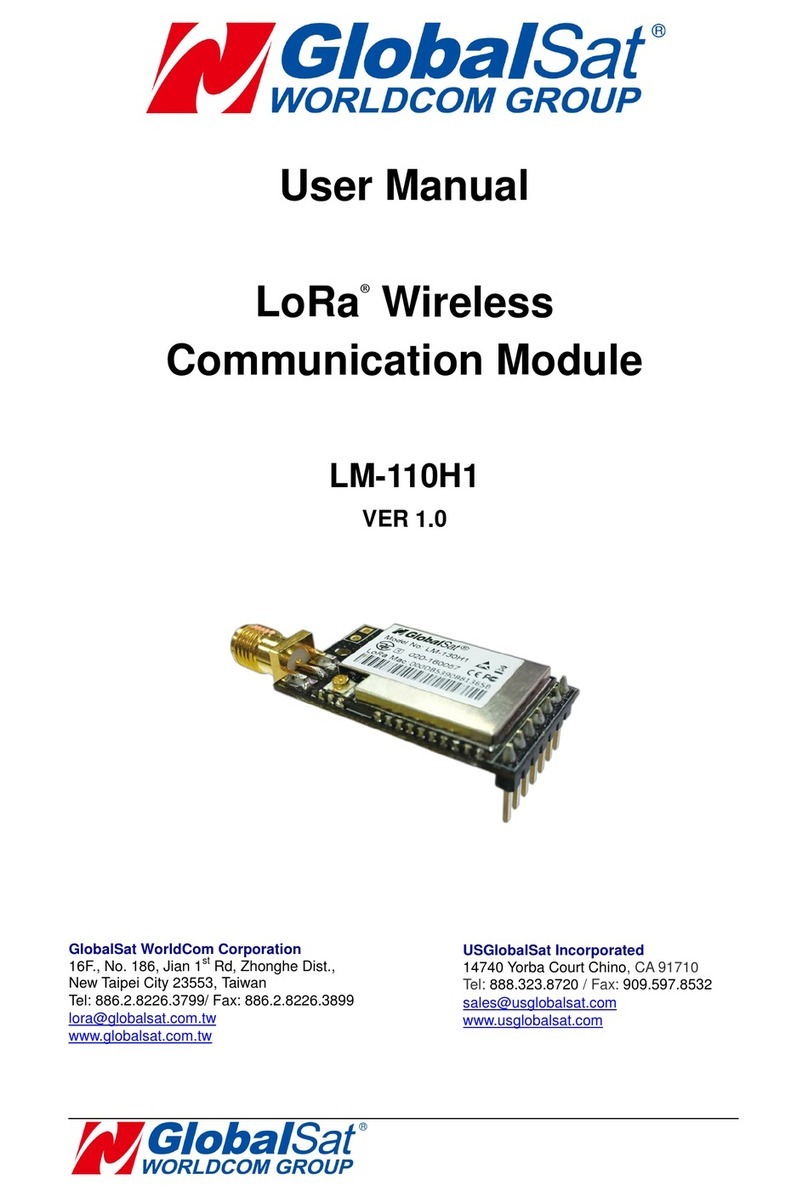
Global Sat LD-11 User manual

LD-11
Operation Manual
Version: 1.0
GlobalSat WorldCom Corporation
16F., No. 186, Jian 1st Rd, Zhonghe Dist.,
New Taipei City 23553, Taiwan
Tel: 886.2.8226.3799/ Fax: 886.2.8226.3899
www.globalsat.com.tw
USGlobalSat Incorporated
14740 Yorba Court Chino, CA 91710
Tel: 888.323.8720 / Fax: 909.597.8532
www.usglobalsat.com

1
CONTENT
1. Introduction..................................................................................................................................2
2. Setup LD-11 .................................................................................................................................3
3. Access into network server...........................................................................................................5
4. Specifications...............................................................................................................................7
5. AT Commands..............................................................................................................................8

2
1. Introduction
LD-11 is a LoRaWAN™ compliant wireless communication module with MiniPCIe
connector interface. It is a low power-consuming and half-duplex module which
can wirelessly transmit data to long-distance. It has built-in high-speed, low
power-consuming MCU and SX1276 modulation chipset. This chipset is applied
with forward error correction technique which greatly improves interference
immunity and advances sensitivity. The coding can detect errors and
automatically filter out errors and false data. LD-11 fully complies with LoRaWAN™
specification and can work with any LoRaWAN™ compliant gateway. It is suitable
for M2M world especially for long-distance transmission or use in harsh environments.
Features:
Mini PCI Express form factor
LoRaWAN™ compliant
Long range transmission (1km to 10km)
2-way duplex communication
High penetration & strong anti-interference capability

3
2. Setup LD-11
LD-11’s component introduction is as below:
1 IPEX antenna connector
2 LM-130 Module
3 Micro USB
4 Mini PCIe

4
To check LD-11’s condition in Windows
1) Please install FT323 driver for micro USB to work in Windows.
2) Please connect LD-11 with PC through micro USB cable.
3) Please install the proper IPEX antenna which supports to your RF frequency.
4) Please refer to “3. Access into network server”to access into network server.
To Install LD-11 into IPC in Linux
5) Please insert LD-11 and set it with your mother board properly as below
picture.
Note: If your mPCIe slot has the screws, please remove them first.
The LD-11 fits in one orientation only. If it doesn't fit, try reversing it.
6) In Linux, please send command (ls /dev/ttyUSB*) to check whether virtual
Com port is. You need to write the program to send AT command through
Com port.
7) Please refer to “3. Access into network server”to access into network server.
Note: Micro USB is used for FW updating and sending AT commands in
Windows. The mPCIe is used for sending AT command only in Linux.

5
3. Access into network server
End-device can be activated by “Over-The-Air Activation”(OTAA) or by “Activation
By Personalization”(ABP). You might need to send AT commands to activate OTAA or
ABP by serial terminal tools. We recommend “RealTerm”. You could download it at the
following link http://realterm.sourceforge.net/.
Please follow the steps below for activating LD-11 to access into the network server.
1. For ABP Mode
1) Make sure the gateway already connect to the internet.
2) Make sure LD-11’s information (DevAddr, AppSKey, NwkSKey) has been
successfully registered to the network server.
3) Use AT command (AAT2 JoinMode=0) to switch LD-11 from OTAA to ABP
mode. You would see “ok” when LD-11 is switched to ABP mode. Use AT
command (AAT1 Save) to save the setting to the flash. You would see “ok”
when the settings are saved. Use AT command (AAT1 Reset) to run the new
settings.
4) Use AT command (AAT2 Tx=2,cnf,aabbccdd) to perform the interop testing.
The payload here is “aabbccdd”. You could set other payload uplink to server.
5) Check if the payload on the network server is correct.
2. For OTAA Mode
1) Make sure the gateway already connect to the internet.
2) Make sure LD-11’s information (DevEUI, AppEUI, AppKey) has been
successfully registered to the network server.
3) Use AT command (AAT2 JoinMode=1) to switch LD-11 from ABP to OTAA
mode. You would see “ok” when LD-11 is switched to ABP mode. Use AT
command (AAT1 Save) to save the setting to the flash. You would see “ok”
when the settings are saved. Use AT command (AAT1 Reset) to run the new
settings.
4) Use AT command (AAT2 Tx=2,cnf,aabbccdd) to perform the interop testing.
The payload here is “aabbccdd”. You could set other payload uplink to server.
5) Check if the payload on the network server is correct.
Note:
The example of our DevEUI, DevAddr and Default key is as following table. DevEUI and

6
DevAddr would be unique for each device. DevEUI and DevAddr can be retrieved by
following AT commands. (AAT2 DevEui=?, AAT2 DevAddr=?)
US ISM Band
EU ISM Band
DevEUI
000DB533188A3572
000DB5331760356B
DevAddr
188A3572
1760356B
Default Key
1. ABP:
NwkSKey=28AED22B7E1516A609CFABF715884F3C
(Hexadecimal number)
AppSKey=1628AE2B7E15D2A6ABF7CF4F3C158809
(Hexadecimal number)
2. OTAA
AppEUI=0000000000010203
(Hexadecimal number)
AppKey=0123456789ABCDEFEFCDAB8967452301
(Hexadecimal number)

7
4. Specifications
LoRa Module
GlobalSat LM-130 LoRaWAN™ Module
RF Band
868/ 915 MHz
USB to UART IC
FTD®232HL
RF Output Power
Max. 20dBm
Receiver Sensitivity
-130dBm
Current Consumption
Receiving: 89mA (typical)
Transmitting: 211mA (typical)
Sleeping: 65mA (typical)
Dimension
50 x 29 x 9 mm
Interface
Mini PCIe / USB
Operation Temperature
-40°C~85°C
Storage Temperature
-40°C~85°C
Operation Humidity
5%~95% (non-condensing)
System Requirements
Windows®7/ 8/ 10 and Linux®Ubuntu 12.04

8
5. AT Commands
All of the LM-130 module’s settings and commands are transmitted over UART using the
ASCII interface. All commands need to be terminated with <CR><LF> and any replies
they generate will also be terminated by the same sequence.
After setting LM-130 module, you must use AT command (AAT1 Save) to save the
settings to the flash. You would see “ok” when the settings are saved. Then use AT
command (AAT1 Reset) to run the new settings.
The settings for the UART interface are 57600 bps, 8 bits, no parity, 1 stop bit, no
flow control.
Note: All AT commands are case sensitive.
Command
Description
AAT1 UpdateFW
Upgrade the LM-130 module firmware.
Response ok after entering the command.
AAT1 Save
All parameters are saved.
Response ok after parameters are saved.
AAT1 FwVersion
Show up firmware version.
AAT1 Reset
Resets and restarts the LM-130 module.
Response ok after entering the command.
AAT1 SLEEP
Put LM-130 into sleep mode.
To leave sleep mode, just Input 0xFF by UART to wake up
LM-130.
Response ok after entering the command.
AAT1 Restore
Restore the defaults of FW.
Response ok after entering the command.
AAT1
TestMode=[parameter1]
[parameter1]:
0: Disable (Active Report Mode: Off)
1: Enable (Active Report Mode: On)
Response:
ok if value is valid
invalid_param if parameter1 is not valid

9
Command
Description
This command sets the state of the active report mode
for the module.
AAT1 TestMode=?
Response:
0: disable (Active Report Mode: Off)
1: enable (Active Report Mode: On)
This command will return the state of the active
report mode.
AAT2
DevAddr=[parameter1]
[parameter1]: 4-byte hexadecimal number representing the
device address, from 00000001 –FFFFFFFF.
Response:
ok if address is valid
invalid_param if parameter1 is not valid
This command configures the module with a 4-byte unique
network device address [parameter1]. The [parameter1]
must be unique to the current network. This must be
directly set solely for activation by personalization devices.
This parameter must not be set before attempting to join
using over-the-air activation because it will be overwritten
once the join process is over.
AAT2 DevAddr=?
Response: 4-byte hexadecimal number representing the
device address, from 00000001 to FFFFFFFF.
This command will return present end-device address of
the module.
AAT2 DevEui=[parameter1]
[parameter1]: 8-byte hexadecimal number representing the
device EUI.
Response:
ok if address is valid
invalid_param if parameter1 is not valid
This command sets the globally unique device identifier for
the module. The identifier must be set by the host MCU.
The module contains a pre-programmed unique EUI and

10
Command
Description
can be retrieved using user provided EUI can be
configured using the AAT2 DevEui command.
AAT2 DevEui=?
Response: 8-byte hexadecimal number representing the
device EUI. This command returns the globally unique
end-device identifier, as set in the module.
AAT2 AppEui=[parameter1]
[parameter1]: 8-byte hexadecimal number representing the
application EUI.
Response:
ok if address is valid
invalid_param if parameter1 is not valid
This command sets the application identifier for the module.
AAT2 AppEui=?
Response: 8-byte hexadecimal number representing the
application EUI. This command will return the application
identifier for the module. The application identifier is a
value given to the device by the network.
AAT2
NwkSKey=[parameter1]
[parameter1]: 16-byte hexadecimal number representing
the network session key.
Response:
ok if address is valid
invalid_param if parameter1 is not valid
This command sets the network session key for the
module. This key is 16 bytes in length, and should be
modified with each session between the module and
network. The key should remain the same until the
communication session between devices is terminated.
AAT2 NwkSKey=?
Response: [parameter1]: 16-byte hexadecimal number
representing the network session key.
This command sets the network session key for the module.
AAT2
AppSKey=[parameter1]
[parameter1]: 16-byte hexadecimal number representing
the application session key.
Response:

11
Command
Description
ok if address is valid
invalid_param if parameter1 is not valid
This command sets the application session key for the
module. This key is unique, created for each occurrence of
communication, when the network requests an action
taken by the application.
AAT2 AppSKey=?
Response: [parameter1]: 16-byte hexadecimal number
representing the application session key.
This command sets the application session key for the module.
AAT2
AppKey=[parameter1]
[parameter1]: 16-byte hexadecimal number representing
the application key.
Response:
ok if address is valid
invalid_param if parameter1 is not valid
This command sets the application key for the module. The
application key is used to identify a grouping over module
units which perform the same or similar task.
AAT2 AppKey=?
Response: [parameter1]: 16-byte hexadecimal number
representing the application key.
This command sets the application key for the module.
AAT2 ADR=[parameter1]
[parameter1]:
0: disable
1: enable
Response:
ok if address is valid
invalid_param if parameter1 is not valid
This command sets if the adaptive data rate (ADR) is to be
enabled, or disabled. The server is informed about the
status of the module’s ADR in every uplink frame it
receives from the ADR field in uplink data packet. If ADR is

12
Command
Description
enabled, the server will optimize the data rate and the
transmission power of the module based on the
information collected from the network.
AAT2 ADR=?
Response:
0: disable
1: enable
This command will return the state of the adaptive data
rate mechanism.
AAT1
EVK_TxCycle=[parameter1]
[parameter1]: decimal number representing the report
interval in seconds, from 1 to 254.
This command will only take effect when “TestMode”=1.
Response:
ok if parameter1 is valid
invalid_param if parameter1 is not valid
This command sets the report interval for the module.
AAT1 EVK_TxCycle=?
Response: decimal number representing the interval, in
seconds, for EVK_TxCycle, from 1 to 254.
This command will return the interval, in seconds, for EVK_TxCycle.
AAT2
JoinMode=[parameter1]
[parameter1]:
0: ABP mode
1: OTAA mode
Response:
ok if address is valid
invalid_param if parameter1 is not valid
This command informs the module activation type.
AAT2 JoinMode=?
Response:
0: ABP mode
1: OTAA mode
This command will return the activation type of module.

13
Command
Description
AAT2 reTx=[parameter1]
[parameter1]: decimal number representing the number
of retransmissions for an uplink confirmed packet, from
0 to 8.
Response:
ok if address is valid
invalid_param if parameter1 is not valid
This command sets the number of retransmissions to be
used for an uplink confirmed packet, if no downlink
acknowledgment is received from the server.
AAT2 reTx=?
Response: decimal number representing the number of
retransmissions, from 0 to 8.
This command will return the currently configured number
of retransmissions which are attempted for a confirmed
uplink communication when no downlink response has
been received.
AAT2
RxDelay1=[parameter1]
[parameter1]: decimal number representing the delay
between the transmission and the first reception window in
microseconds, from 100000 to 10000000.
Response:
ok if address is valid
invalid_param if parameter1 is not valid
This command will set the delay between the transmission
and the first reception window to the [parameter1] in
microseconds. The delay between the transmission and
the second Reception window is calculated in software as
the delay between the transmission and the first Reception
window + 1000000 (μs).
AAT2 RxDelay1=?
Response: decimal number representing the interval, in
microseconds, for RxDelay1.
This command will return the interval, in microseconds,
for RxDelay1.

14
Command
Description
AAT2 Tx=[parameter1],
[parameter2],
[parameter3]
[parameter1]: decimal number representing the port
number, from 1 to 223.
[parameter2]: string representing the uplink payload type,
either “cnf” or “uncnf”. (cnf = confirmed, uncnf =
unconfirmed)
[parameter3]: hexadecimal number representing the
payload value.
The length of [parameter3] bytes capable of being
transmitted are dependent upon the set data rate. (Please
refer to the LoRaWANTM Specification for further details)
Response: This command may reply with two responses.
The first response will be received immediately is valid (ok
reply received), the second reply will be received after the
end of the uplink transmission. (Please refer to the the
LoRaWANTM Specification for further details.)
Response after entering the command:
ok - if parameters and configurations are valid.
Invalid_param –if parameters
( [parameter1],[parameter2],[parameter3]) are not valid.
Tx_ok - if “cnf” radio Tx return with ACK
Tx_ok - if “uncnf” radio Tx return
Tx_noACK –if ”cnf” radio Tx return without ACK
Rx < parameter1> < parameter2> –if transmission
was successful, [parameter1] port number, from 1 to
223; [parameter2] hexadecimal number that was
received from the server.
AAT2
DutyCycle=[parameter1]
[parameter1]:
0: disable
1: enable
Response:

15
Command
Description
ok if address is valid
invalid_param if parameter1 is not valid
This command sets the state of the duty cycle. You
could set the ratio of duty cycle by AAT2
Tx_Band=[parameter1],[parameter2],[parameter3].
For the details, please refer to the command above.
AAT2 DutyCycle=?
Response:
0: disable
1: enable
This command will return the state of the duty cycle.
AAT2
PLCheck=[parameter1]
[parameter1]:
0: disable
1: enable
Response:
ok if address is valid
invalid_param if parameter1 is not valid
This command sets the payload length’s verification.
AAT2 PLCheck=?
Response:
0: disable
1: enable
This command will return the state of payload
length’s verification.
AAT2 Rx2_Freq_DR=
[parameter1],[parameter2]
[parameter1]: decimal number representing Rx2 frequency,
from 000000001 to 999999999 in Hz.
[parameter2]: decimal number representing Rx2 Data
Rate, from 0 to 15.
Response:
ok if address is valid
invalid_param if parameter1 is not valid

16
Command
Description
This command sets the frequency and Data Rate of Rx2.
AAT2 Rx2_Freq_DR=?
Response: decimal number representing the frequency
and Data Rate of RX2.
This command will return the frequency and Data Rate of
RX2. When RX2 frequency is 915MHz and Data Rate is 3,
the response message is as “Freq.915000000, DR3”.
AAT2
ClassMode=[parameter1]
[parameter1]:
0: Class A
2: Class C
This command sets the operation mode of the module.
AAT2 ClassMode=?
Response:
0: Class A
2: Class C
This command will return the operation mode of module.
AAT2
Rx1DrOffset=[parameter1]
[parameter1]: decimal number representing the index of
Rx1 offset, from 0 to 3.
This command sets the index of Rx1 offset. The
Rx1DrOffset sets the offset between the uplink data rate
and the downlink data rate used to communicate with the
end-device on the first reception slot (Rx1). As a default
this offset is 0. The offset is used to take into account
maximum power density constraints for base stations in
some regions and to balance the uplink and downlink radio
link margins.
AAT2 Rx1DrOffset=?
Response: decimal number representing the index of
Rx1 offset.
This command will return the index of Rx1 offset.
AAT2 Tx_Channel=
[parameter1],[parameter2]
[parameter3],[parameter4]
[parameter5]
[parameter1]: decimal number representing the channel
number. The range for US is from 0 to 71. The range for
EU is from 0 to 15.
[parameter2]: decimal number representing the frequency
of TX channel, from 000000001 to 999999999 in Hz.

17
Command
Description
[parameter3]: 2 digit decimal numbers representing the
operating range of Data Rate. (The left one is DR’s Max,
the right one is DR’s Min.) The range of DR is from 0 to 15.
Note: According to LoRaWAN_Regional_Parameter.pdf,
Data Rate in some regions will be limited in a particular
range. For example, upstream 64 channels numbered 0 to
63 utilizing LoRa 125 kHz BW varying from DR0 to DR3 for
US.
[parameter4]: 0/1 representing the channel is close/open.
[parameter5]: decimal number representing the number of
band grouping. The range for US is 0. The range for EU is
from 0 to 3.
Please refer to AAT2 Tx_Band=[parameter1],
[parameter2],[parameter3] for further understanding.
Response:
ok if address is valid
invalid_param if one of parameters is not valid.
This command sets the frequency, Data Rate, status and
the number of band grouping for assigned Tx channel.
For example:
AAT2 Tx_Channel=3,973300000,40,1,0
Description:
Modify Channel 3 to have the settings below.
973300000 = Frequency
40 = DR Range; (4=DR Max, 0=DR Min)
1=Status ;(1=open)
0= the number of band grouping
AAT2 Tx_Channelx=?
Response: the assigned Tx channel will be shown.
Variable xneeds to be assigned as channel number.
This command will show the assigned Tx channel.
For example:
AAT2 Tx_Channel15=?
Channel15 message will be shown as below:

18
Command
Description
channel_15,Freq.905300000,DrRange.0-3,Status0,
Band0
AAT2 Tx_Band=
[parameter1],
[parameter2],
[parameter3]
[parameter1]: decimal number representing the number of
band grouping. The range for US is 0. The range for EU is
from 0 to 3.
[parameter2]: decimal number representing the value of
duty cycle, from 1 to 9999. The real duty cycle could be
calculated as (100% / duty cycle value).
[parameter3]: decimal number representing the index of Tx
power, from 0 to 15.
Response:
ok if address is valid
invalid_param if one of parameters is not valid.
This command sets duty cycle and Tx power for the
assigned number of band grouping.
For example:
AAT2 Tx_Band=0,50,5 (for US)
Description:
The real duty cycle = 100% / 50 = 2%
Modify band grouping 0 to set duty cycle as 2% and Tx
power index as 5 (20dBm).
AAT2 Tx_Band=?
Response: the list of all Tx bands will be shown.
This command will show the list of all Tx bands.
AAT2 Tx_Bandx=?
Response: the assigned Tx band will be shown. Variable x
needs to be assigned as band grouping number.
This command will show the assigned Tx band.
For example:
AAT2 Tx_Band0=?
The message will be shown as below:
Band_0, DutyCycle.1, TxPower.5
AAT2 Uplink_Count=?
Response: decimal number representing the number of
uplink frame counter.
This command will return the number of uplink

19
Command
Description
frame counter.
AAT2 Downlink_Count=?
Response: decimal number representing the number of
downlink frame counter.
This command will return the number of downlink
frame counter.
AAT2 Tx_Power=
[parameter1],[parameter2]
[parameter1]: decimal number representing the index of Tx
power from 0 to 15.
[parameter2]: decimal number representing the real
TxPower. The range for US is 0 to 30. The range for EU is
from 0 to 20.
Response:
ok if address is valid
invalid_param if one of parameters is not valid
This command sets the index of Tx power and the real Tx
power for Tx power table.
AAT2 Tx_Power=?
Response: the Tx power table will be shown.
This command will show Tx power table.
AAT2 Tx_Powerx=?
Response: the real power of assigned Tx power index
will be shown. Variable xneeds to be assigned as Tx
power index.
This command will show the real power of the assigned Tx
power index.
For example:
AAT2 Tx_Power2=?
The message will be shown as below:
TxPower_2, 26 dBm.
AAT2 Pl_Max_Length=
[parameter1],[parameter2]
[parameter1]: decimal number representing Data Rate
from 0 to 15.
[parameter2]: decimal number representing maximum
application payload length (N) from 0 to 255.
Response:
ok if address is valid
invalid_param if one of parameters is not valid
Table of contents
Other Global Sat Control Unit manuals
Popular Control Unit manuals by other brands

Radiocrafts
Radiocrafts MBUS Series user manual

GF
GF Signet 9950 instruction sheet

Tektronix
Tektronix VX4286 user manual

Becker
Becker Centronic SunWindControl SWC245-II Assembly and operating instructions

Panasonic
Panasonic CF-BAP0128U operating instructions

resideo
resideo Braukmann SG160S installation instructions