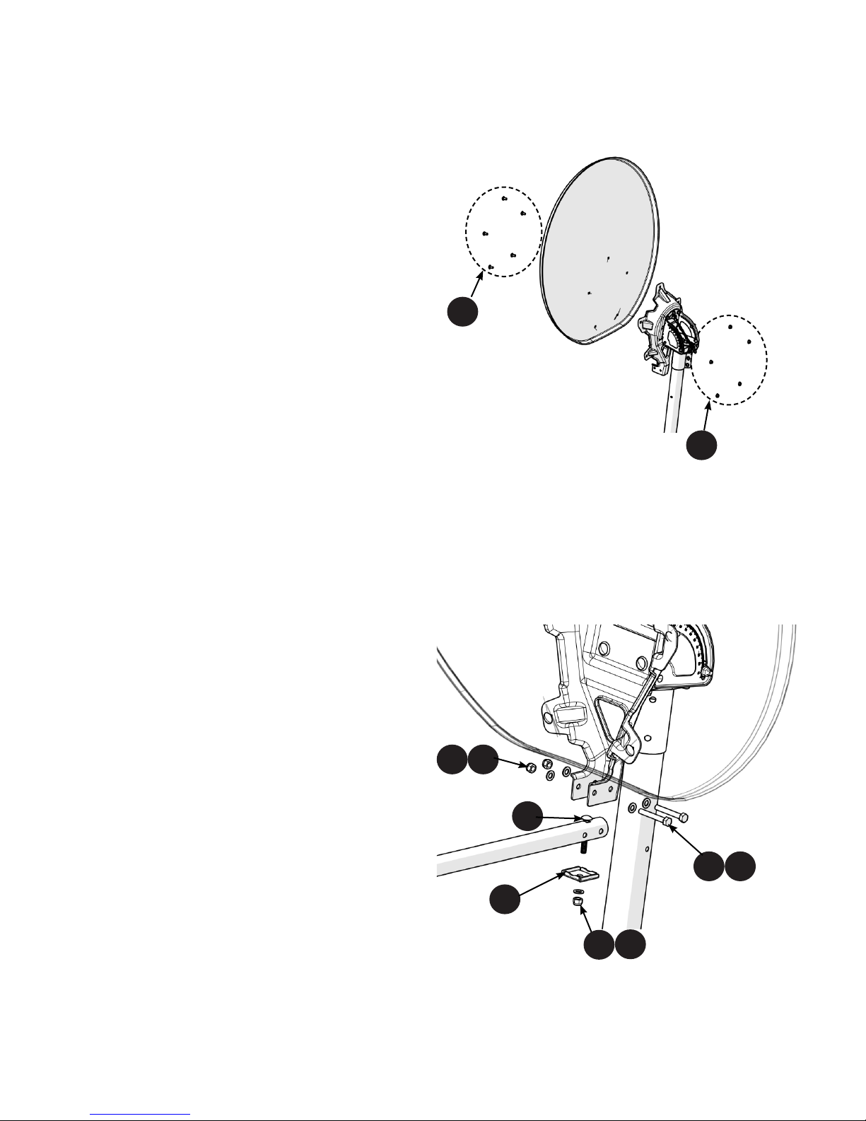
Elevaon Fine Adjustment
1. Make nal adjustments to the elevaon by making slight
adjustments to the 5/16” ange nuts on the threaded
elevaon rod.
2. Adjust the nuts along the length to increase or decrease
the seng to achieve the desired elevaon.
3. Aer the correct elevaon has been established, ghten
the two(2) 5/16” ange nuts located in the arched slots
on the side of the Mount Assembly to 20 Nm (15 – lb)
and ghten the two(2) 5/16” ange nuts on the threaded
elevaon rod using a 1/2" wrench.
Elevaon Coarse Adjustment
1. Slightly loosen the two(2) 5/16” ange nuts located in the
arched slots in the sides of the Mount assembly and the two(2)
5/16” ange nuts on the threaded adjustment rod at the back of
the assembly.
2. Adjust the posion of the 5/16” ange nuts on the threaded
adjustment rod along the length of the rod to adjust the elevaon
angle, moving the nuts up & down to nd the correct posion.
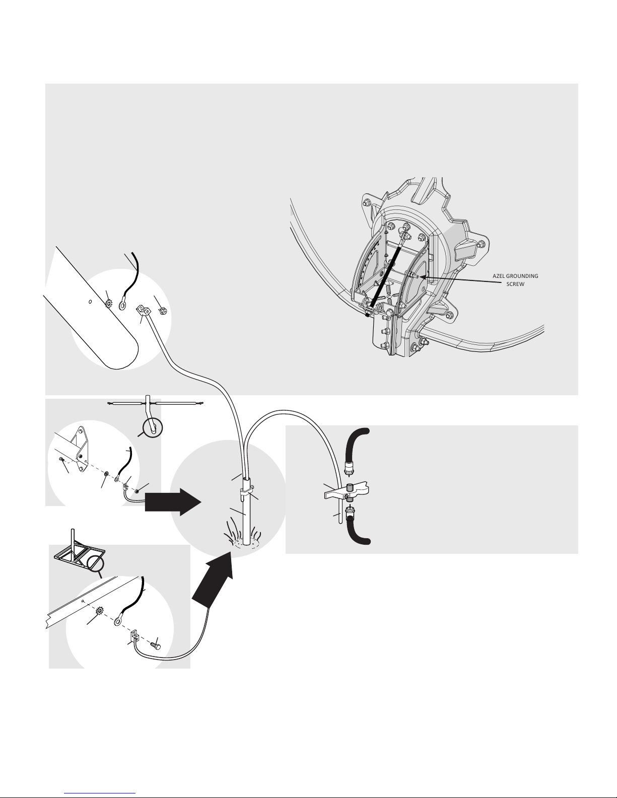
Azimuth Coarse Adjustment
1. Using a compass, set the Antenna in the correct pre-determined
direcon.
2. Secure this posion by fully ghtening the three(3) 5/16”
locking nuts to the canister using a 1/2" wrench.
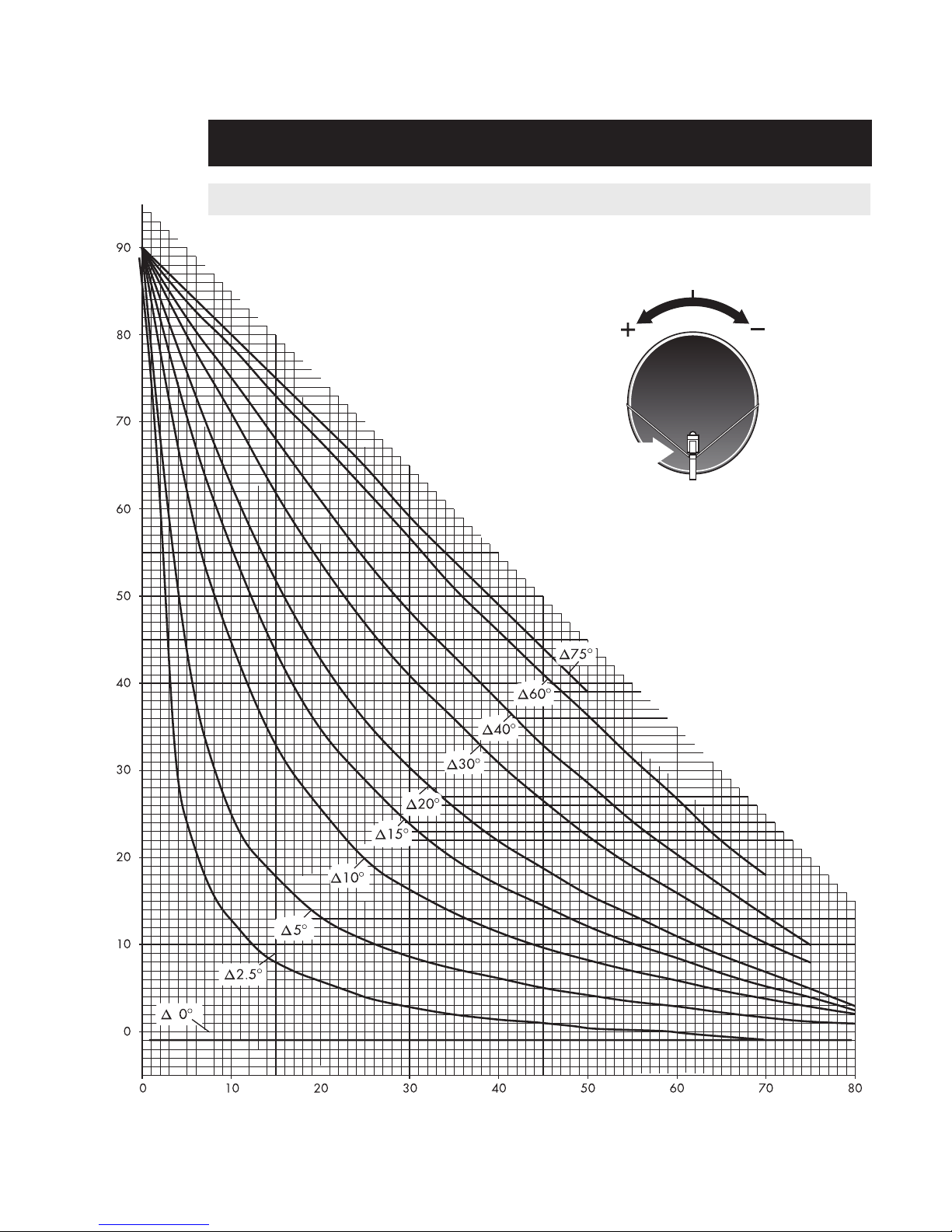
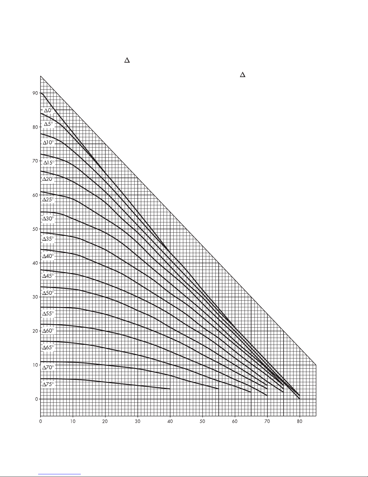
2.1 ANTENNA ALIGNMENT PROCEDURE
Azimuth Fine Adjustment
1. Slightly loosen the three(3) 5/16” locking nuts mounted to
the underside of the mount assembly.
2. Adjust the azimuth by turning the adjustment screw
clockwise or counter-clockwise unl the desired angle is
achieved.
3. Aer vericaon with a compass and meter, re-lock the
5/16” nuts to 20 Nm (15 – lb) using a 1/2” wrench.
5
5/16” Flange
Nuts
5/16” Locking
Nuts
5/16” Locking Nuts
5/16” Flange Nuts
Azimuth
Adjustment
Screw