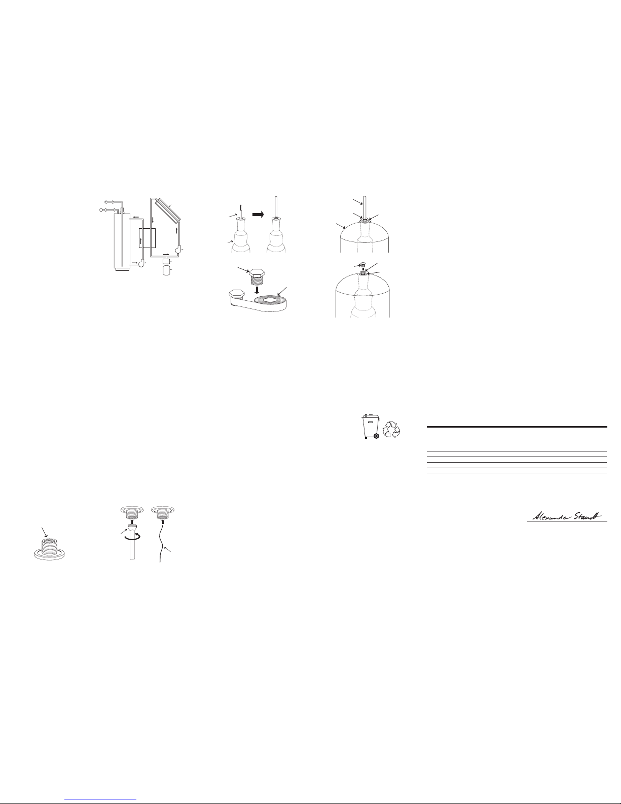
hanger is protruding from the top of the tank and the threads are visible.
10. Slip the washer and then the hanger nut over the end of the rod/cable and tighten onto the exposed
connector (g. 4.4).
11. After tightening the hanger nut onto the exposed connector, disconnect and remove the rod.
12. If applicable; use silicon tape to thoroughly wrap and seal the hanger connector sealing bolt (g. 4.5).
13. If applicable; insert the sealing bolt into the open connector, ensure it is properly seated and tighten it.
Do NOT over-tighten (g. 4.6).
14. Fill 2 bar (30 psi) of precharge air or nitrogen and using a soap solution check for leaks all around the
air valve, pressure gauge, top nut and bottom ange.
15. Lift tank upright and attach to pressure system as described earlier in this manual.
16. Open gate valve and allow some water into tank and then pump more air/nitrogen to set tank to
appropriate precharge as described in section 1.3.
17. Now open isolation gate valve to allow full functionality of tank.
Note: For tanks with a ange instead of a hanger on top of the tank, rst mount the membrane to the
top ange.
5. Disposal
Check with local authorities for proper disposal and recycling. Do not
dispose of the manual - keep it for further reference.
6. Warranty
Global Water Solutions Ltd. (GWS) warrants its SuperFlow™ tanks for a period of 1 years from the
date of manufacture for manufacturing defects on the steel shell.Warranty applies to GWS products
only when used for their intended purpose, and does not apply if a defect is due to improper use of
the product, result of accident, misuse, or abuse. If the product was improperly installed or altered in
any way, not specically authorized by the factory, the warranty is void. The warranty set forth in this
paragraph is made expressly in lieu of all other warranties expressed, or implied, including but not
limited to merchantability or tness for a particular purpose.
For replacement of the membrane, provided the tank is installed by an authorized installer and
pre-charge is set properly as per instruction manual and the pre-charge is checked as per the same
manual at a time interval of every 3 months, warranty is granted for a period of 3 months from date of
manufacture on membrane defects.
In no event shall GWS be liable for cost of processing, lost prots, goodwill or any other consequential
or incidental damage of any kind resulting from the order or use of its products whether arriving from
breach of warranty, nonconformity to ordered specications, delay in delivery, or any loss sustained by
the buyer nor will GWS be liable for labor and expenses necessary to remove and reinstall replacement
product.
To obtain service under this warranty, consumer must deliver alleged defective product, freight prepaid,
to an authorized GWS distributor or OEM partner. GWS will either issue credit or at its option, repair
or replace defective product freight prepaid to the distributor. GWS reserves the right to make changes
in construction, which, in its judgment, constitutes a product improvement.
All warranty is subject to veriable proper installation, adjustment of pre-charge as per our engineering
bulletins and installation of a pressure relief valve as recommended in the installation manual.
Standard manufacturer’s warranty as dened in the standard GWS warranty terms and conditions.
2.4 Solar Heating System
Connections
SuperFlow™ tanks can be used in the solar
liquid loop of indirect thermal transfer systems
and may be mounted either on the suction
or pressure side of the circulation pump.
If a condenser is employed to cool evaporated
solar liquid it must be in the location between
the solar liquid loop and the expansion tank. A
relief valve should be employed and maximum
operating parameters must not be exceeded.
If the temperature of the solar system has the
potential to rise above the evaporation point
of the solar liquid, a condenser chamber or coil
is required between the solar collector and the
expansion tank (See Fig. 2.4).
2.5 Thermal Expansion Operating Principles
As water is heated it expands. A thermal expansion tank is used to accommodate for this natural water
expansion, which otherwise may lead to increased system pressure and cause damage to piping, ttings
and other system components. A thermal expansion tank uses a membrane sealed inside the vessel to
create a barrier between water and air chambers.The air chamber acts as a cushion which compresses
as heated water expands.The thermal expansion tank absorbs the expanded water volume and ensures
constant system pressure is maintained. Using a thermal expansion tank also conserves water and energy.
This is accomplished by eliminating the need to rell and reheat water lost due to venting from the relief
valve during heating cycles.
3. Maintenance
SuperFlow™ pressure tanks should be checked by an authorized service professional, every 3 months.
To check precharge, shut off power to the pump, isolate and drain the tank. Check precharge using a
pressure gauge. If needed, top up air to appropriate precharge level using an air pump or compressor.
Open isolation gate valve allowing the pump to ll the tank with water.
Always release all water and air from tank before disassembling the parts exposed to pressure such
as anges, air valve, pressure gauge etc. Make sure that the system is switched off and no electricity or
electrical devices are running.
If the pump short cycles or the heating system relief valve constantly opens, check the air valve mounted
on the tank. If water bleeds from the valve the membrane has burst. Please call an authorized service
provider to replace the membrane with a factory replacement, following the instructions for membrane
replacement in this manual.
Check the quality of the water by draining water from the tank using the drain valve. If the water is
rusted, calcied, or has solid deposits, then either the membrane has failed which can be veried by above
mentioned process or the tank is blocked.
4. Membrane Replacement Instructions
1. Turn off the water and/or disconnect the power to the pump.
2. Release the air and drain all water from tank.
3. Unbolt and remove the ange (water connection) from the tank.
4. Remove the nut and the washer on the top of the tank which is attached to the membrane hanger
that is anchoring the top of the membrane (g. 4.1, g. 4.4).
5. Pull and remove the membrane through the bottom opening to which the ange was attached.
6. Remove the top connection membrane hanger from the damaged membrane, this can be reused
and should be cleaned.
7. Take the membrane hanger and attach it to a rod, a cable or alike, as seen in g. 4.2.
8. Pull the rod and hanger up through the membrane until the top of the hanger is protruding from the
top of the membrane (g. 4.3).
9. Feed the rod from the bottom of the tank up through the opening at the top of the tank until the
Hot
Cold
Pump
Pump
Solar Collector
Condenser
Solar
Tank
Storage
Tank
Heat
Exchanger
Fig. 2.4
Fig. 4.2
rod
cable
Fig. 4.3
membrane
rod or cable
Fig. 4.5
hanger connector
sealing bolt
silicon tape
Fig. 4.6
hanger connector
sealing bolt washer
hanger nut
Fig. 4.4
rod or cable
hanger nut washer
tank
membrane hanger
Fig. 4.1
EC declaration of conformity
We, Global Water Soluons Ltd., declare under
our sole responsibility that the pressure vessels
types MBPA / MBPC, to which this declaraon
relates, are in conformity with these Council
direcves on the approximaon of the laws of the
EC member states:
The products are diaphragm tanks. All products are examined under these condions:
Type Maximum
Pressure [bar]
Volume
[litres]
Category Used Design
Standard
MBPA-10 10 8-10000 II, III, IV EN13831:2007
MBPA-16 16 8-10000 II, III, IV EN13831:2007
MBPA-25 25 8-10000 II, III, IV EN13831:2007
MBPC-10 10 8-500 II, III, IV EN13831:2007
Fluid group: 2 Module: B + D Cercate Number: 458-C02-00-TR-PED-14-092
Noed body: CE 2513 - Ali Nihat Tarlan Cad. No: 103 D: 9 Küçükbakkalköy Ataşehir / Istanbul
Manufacturer: Baris Mah. Tübitak Yolu Anibal Cad.No:23 Gebze / Kocaeli / Turkey
Konformitätserklärung
Wir, Global Water Soluons Ltd. erklären in
alleiniger Verantwortung, dass die Druckbehälter
Typ MBPA / MBPC, auf die sich diese Erklärung
bezieht, mit den folgenden Richtlinien des Rates
zur Angleichung der Rechtsvorschrien der EU-
Mitgliedsstaaten übereinsmmen:
Dichiarazione di Conformità
Global Water Soluons Ltd. dichiara soo la sua
esclusiva responsabilità che i vasi di espansione
po MBPA / MBPC, ai quali si riferisce questa
dichiarazione, sono conformi alle seguen direve
del Consiglio riguardan il riavvicinamento delle
legislazioni degli Sta membri CE:
Declaração de Conformidade
A Global Water Soluons Ltd. declaramos sob
nossa única responsabilidade que os tanques
de pressão type MBPA / MBPC, aos quais diz
respeito esta declaração, estão em conformidade
com as seguintes Direcvas do Conselho sobre
a aproximação das legislações dos Estados
Membros da CE:
Försäkran om överensstämmelse
Vi, Global Water Soluons Ltd. försäkrar härmed
a tryckkärl av typen MBPA / MBPC, som omfaas
av denna försäkran, är i överensstämmelse med
rådets direkv om inbördes närmande ll EU-
medlemsstaternas lagsning, avseende:
Overensstemmelseserklæring
Vi, Global Water Soluons Ltd. erklærer
under ansvar, at trykbeholdere type MBPA
/ MBPC, som denne erklæring omhandler,
er i overensstemmelse med disse af Rådets
direkver om indbyrdes lnærmelse l EF-
medlemsstaternes lovgivning:
Déclaration de Conformité
Nous, Global Water Soluons Ltd., déclarons
sous notre seule responsabilité, que les vases
d’expansion type MBPA / MBPC, auxquels se réfère
cee déclaraon, sont conformes aux Direcves
du Conseil concernant le rapprochement des
législaons des Etats membres CE relaves aux
normes énoncées ci-dessous :
Declaración de Conformidad
Nosotros, Global Water Soluons Ltd. declaramos
bajo nuestra única responsabilidad que los
tanques a presión type MBPA / MBPC, a los cuales
se reere esta declaración, están conformes con
las Direcvas del Consejo en la aproximación de
las leyes de las Estados Miembros del EM:
Декларация Соответствия
Мы, компания Global Water Soluons Ltd.,
полностью несем ответственность за то, что
сосудов под давлением типов MBPA / MBPC,
к которым относится настоящая декларация,
соответствуют следующим Директивам Совета
Евросоюза об унификации законодательных
предписаний стран-членов ЕС:
Vastaavuusvakuutus
Me, Global Water Soluons Ltd. vakuutamme,
eä valmistamamme paineasat type
MBPA / MBPC, joita tämä vakuutus koskee,
ovat EY:n jäsenvaloiden lainsäädännön
yhdenmukaistamiseen tähtäävien Euroopan
neuvoston direkivien vaamusten mukaisia
seuraavas:
DECLARATION OF CONFORMITY
Pressure Vessels Types MBPA / MBPC
Alexander Staudt
Technical Manager
Luxembourg, July 1st, 2016Global Water Solutions Ltd.
5th oor, 37 Esplanade
St. Helier – JE1 2TR
Jersey
The Channel Islands
PED 2014/68/EU


 Operation and maintenance instructions")