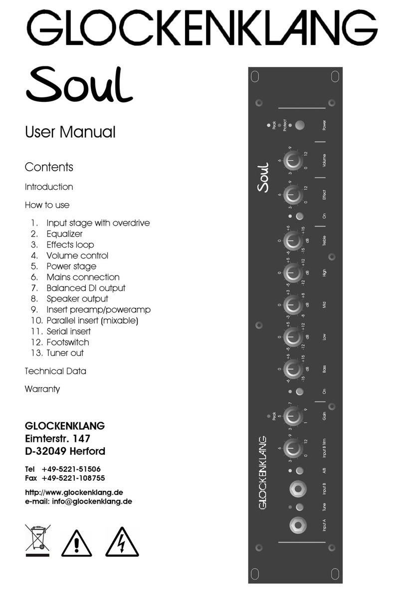
GLOCKENKLANG Bass Art Classic User manual

Head
User Manual
Contents
Introduction
How to use
1. Input stage
2. Equalizer
3. Effects loop
4. Volu e control
5. Power stage
6. Mains connection
7. Speaker + Phones output
8. Parallel insert ( ixable)
9. Footswitch
10. Balanced DI output
11. Tuner out
12. Serial insert
13. Insert prea p/powera p
Technical Data
Warranty
GLOCKENKLANG
Ei terstr. 147
D-32049 Herford
Tel +49-5221-51506
Fax +49-5221-108755
http://www.glockenklang.de
e- ail: info@glockenklang.de

Thank you for choosing the GLOCKENKLANG
Bass Art Classic a plifier. You have
purchased an exquisite piece of equip ent,
which was designed after the ost odern
technical aspects.
Attention!
To activate your additional 3 years warranty,
you should send in the enclosed warranty
card.
Please enter the serial nu ber of your
a plifier and the date of purchase and
send it to :
Glockenklang
Ei terstrasse 147
D-32049 Herford
Ger any
This serves as a easure to ensure excellent
custo er service in the future.
For your safety
Please read the following instructions
carefully. These tips will ensure long and
troublefree operation of your new
GLOCKENKLANG product.
Operational restrictions
Do not operate the a plifier under the
following conditions:
• In direct sunlight
• In extre ely dirty or dusty places
• In extre ely hu id or wet places
• Around heat e itting appliances
Caution: When rack mounting the
amplifier, make sure to leave adequate
room for ventilation. he unit needs this
ventilation space to adequately exhaust it
´s internally generated heat.
Handling
Do not drop the a p. Do not use excessive
force when activating switches and dials.
Care
Use a soft, clean and dry cloth only to clean
the a plifier. Do not use aggressive
che icals to clean the housing. Do not use
co pressed air to clean the housing. You
ay carefully vacuu the air intake and
exhaust areas fro ti e to ti e to re ove
loose dust accu ulation.
Please, keep this User Manual for future
references
General instructions
Your Bass Art Classic head´s special features:
• 3 effect loops
"insert" is a serial loop
"effect" is a parallel loop with
blending control fro 0% till 100% on the
front panel,
"prea p out" / "powera p in" is a
second serial loop.
The insert is switched pre eq, the effect
loop is switched post eq/pre volu e
control/pre DI out.
The effect loop is internally switachable –
with the dip-switch in off position, behind
the effect control pot – to an effect-
intensity fro 0 till 50% with an equal
level of original signal, which gives you a
s all rise of the whole level by adding
the effectlevel.
Prea p Out - Powera p In are post
aster volu e/post eq/post DI. This
send/return is very useful for use of
equalizers and stage sound processors
that are not desired to go to the DI
output.
• Powera p protection circuit
The powera p is short circuit , high
te perature and DC voltage protected.
In case of short circuit, high te perature
or DC current the yellow "Protect" LED will
co e on.
• The powera p includes a peak li iter
to reduce overdrive-distortion of the
outputstage. The yellow LED lites, when it
is working.
Caution:
Please ensure adequate ventilation when
rack ounting the Bass Art Classic a p.
Leave a ini u of 5 space below
and above the a plifier. Make sure that
the airflow at the heatsink on the back is
unobstructed. Use a rack not deeper
than 25 c , otherwise use a fan.


1.1 Line Driver In XLR-Connector
Input for the optional instru ent line driver. Is
connected to the switch-contact of the Input B
jack. Will be deaktivated by putting in an
instru ent-cable into Input B jack.
1.2 Input A Jack
Nor al instru ent input
1.3 A/B Switch
Activates Input A or Input B, enabling switching of
two instru ents.
1.4 Input B Jack
Instru ent input for high level instru ents.
Adjustable via Input B Tri knob.
1.5 Tune Switch (Mute-Function)
Mutes all outputs but the Tuner Out.
Can be activated by footswitch.
1.6 Tri Input B Control
Pre gain tri for Input B, you can adjust the level
between 0 dB and -20 dB.
1.7 Gain Control with Peak LED
Matches input signal to prea p. To adjust, turn
knob until the Peak LED above the control only
flickers at highest and loudest peaks. The level in
the Effect Loop is then adjusted to +4 dB and
the headroo to overdrive is 20 dB.
2.1 Treble/Bass Eq with On Switch
Bass and Treble controls serve to fine tune your
sound or solve acoustical proble s on stage.
They will be activated by the On Switch. The
frequencies are centered at 60 Hz and 12 KHz.
2.2 Mid Eq with On Switch
Low Mid and High Mid se ipara etrical
equalizer. The „dB“-controls raise and dip the
frequencies, which are centered by the
„KHz“-controls.
3.1 Effect Control
Mixes the effects loop into the original signal fro
0% ( original signal only) to 100% (effect only).
The effect loop is internally switachable – with the
dip-switch in off position, behind the effect control
pot – to an effect-intensity fro 0 till 50% with an
equal level of original signal, which gives you a
s all rise of the whole level by adding the effect
level.
3.2 Effect On Switch
Activates the Effect Loop ( Parallel Loop ). This
feature can also be activated by foot switch.
4.1 Volu e Control
Serves as ain volu e control for the Line Out
jack and XLR-connector on the rear.
5.1 Power Switch
A/C Switch to turn on power to the unit. Power On
is indicated by a green LED.
5.2 Protect LED
Illu inates when one of the protection circuits
activates. The speakers will be disconnected with
this light on.
5.3 Peak LED
Lites when the peak li iter of the powera p
begins to work. It warns of possible overdrive-
distortion.

Ground
Lift
post
pre
1 , 2+, 3-
Prea p
Out
Made in Ger any
Level
Out
100
27540
Hz
25 500
Effect Loop
Return Send TuneLoop
Footswitch
Basscut
DI
Ground
Lift
post
pre
1 , 2+, 3-
Level
Out Tuner
Out
Return Send
Insert
On
230 V / 3,15 AT
120 V / 6,3 AT
Powera p In
On
Speaker Out
in. load 4 oh s
Pin 1+, 2+ hot / Pin 1-, 2- cold
WARNING! DO NOT OPEN! NO USER SERVICEABLE PARTS INSIDE!
REFER SERVICING TO QUALIFIED PERSONNEL!
ACHTUNG! Gerät nicht öffnen, gefährliche Spannung! Gerät vor Feuchtigkeit und Hitze schützen!
Top
Phones
6.1 A/C Connector with fuse
Connector for A/C cord. The fuse is located in the s all
co part ent below. A spare fuse is included in the
co part ent. The fuse is rated at 3,15A/slo for 230V
operation and 6.3A/slo for 120V operation.
7.1 Speaker Out Connector
4-pole speakon jacks for speaker connections. These
jacks are in parallel. Connect one 4 oh s or two 8
oh s cabinets here. The axi u power rating is 400
watts into 4 oh s, the ini u per issible speaker
i pedance is 4 oh s. Connections are pins +1 and
+2 hot, pins –1 and –2 cold.
7.2 Phones Out Jack
Output for a Mono- or Stereo-headphone, the signal is
in ono. Adjust outputsignal with the volu e control.
8.1 Loop Return Jack
Connect to the output of an effects processor, that is
supposed to be looped into the effects loop. Can be
used as a ix input (i.e. an additional prea p, the ix
ratio can be adjusted at the Effect control on the front.
8.2 Loop Send Jack
To be connected to an effects units input. The level is
+4dB
8.3 Basscut Frequency Control
Cuts the low frequencies of the send signal with
12db/octave, to suppress the influence of an effect like
reverb or flanger to the key-notes.
9.1 Footswitch Loop Jack
Serves as a connection for the loop function footswitch.
It has the sa e function as the loop button on the
a p front.
9.2 Footswitch une Jack
Serves as a connection for the ute function
footswitch. It has the sa e function as the ute button
on the a p front.
10.1 Ground Lift Switch
Separates Signal Ground fro Chassis Ground to
eli inate hu and buzz, when connecting other A/C
connected gear.
10.2 DI Out XLR Connector
This is the output of the integrated DI Box. It is for
balanced connectivity to ixing consoles. The signal is
routed to this output pre-volu e control for
independent stage volu e adjust ent possibilities.
Caution!
This output is electronically balanced. Do not ground
pin 3, when using unbalanced cables in this jack. Pin
3 is unused for unbalanced operation!
10.3 DI pre/post Switch
Chooses a ong the following DI odes:
pre: before eq and serial insert
post: post eq and serial/parallel insert
offers a choice between pure or processed bass guitar
signal
10.4 DI Level Control
Matches DI output with ixing console input
11.1 uner Out Jack
Serves as a connection for a tuner. This output is always
active.
12.1 Insert Return Jack
Connect to the output of an effects unit for use in a
serial configuration.
12.2 Insert On Switch
Activates the insert function.
12.3 Insert Send Jack
The input of an effects unit for serial configuration (i.e.
equalizer or co pressor). The signal level is +4dB. The
signal is taken post gain, but pre eq.
13.1 Preamp Out Jack
This jack carries the pre-a plified signal post volu e
control. This can serve as a connection for a second
power a p or as a send for effects that are only used
for stage sound and not sent to the DI.
13.2 Poweramp In On Switch
Activates the powera p in jack (insert function).
13.3 Poweramp In Jack
This leads directly to the powera p section of the
head, for using external prea ps. Also serves as return
for the second serial insert.
Table of contents
Other GLOCKENKLANG Amplifier manuals

GLOCKENKLANG
GLOCKENKLANG Blue Soul User manual

GLOCKENKLANG
GLOCKENKLANG Bugatti User manual

GLOCKENKLANG
GLOCKENKLANG Heart-Rock User manual

GLOCKENKLANG
GLOCKENKLANG Bass art Classic User manual

GLOCKENKLANG
GLOCKENKLANG Blue Rock User manual

GLOCKENKLANG
GLOCKENKLANG Soul User manual

GLOCKENKLANG
GLOCKENKLANG Bass Art Classic User manual

GLOCKENKLANG
GLOCKENKLANG Blue Sky User manual

GLOCKENKLANG
GLOCKENKLANG Blue Soul User manual

GLOCKENKLANG
GLOCKENKLANG Blue Sky User manual