GLT Fox-Up User manual

R
INSTALLATION AND OPERATING INSTRUCTIONS
MONTAGE- UND BEDIENUNGSANLEITUNG
INSTALLATIE- EN BEDIENINGSHANDLEIDING
INSTRUCTIONS D’INSTALLATION ET D’UTILISATION
FOX-UP

Installation and operating instructions - English ...........................................................................1
Montage- und Bedienungsanleitung - Deutsch...........................................................................27
Installatie- en bedieningshandleiding - Nederlands.................................................................. 53
Instructions d’installation et d’utilisation - français..................................................................79
R

1
EN
Due to an easy mounting, the units of the Fox Up series are suitable in new buildings and for refurbishment purposes. Fox Up allows for
hygienic air exchange in line with the standards. The units work as a decentralized system and are mounted completely in the outer walls.
There is no need for piping across rooms or floors nor for complex cleaning concepts.
INSTALLATIONANDOPERATINGINSTRUCTIONS-ENGLISH
OPERATINGINSTRUCTIONS
Storingthemanual
All service providers involved in mounting, connection and the set-up of the Fox up ventilators needs the information of this manual in order
to do the work correctly. Please make sure that the manual is available for them.
Please give all users a copy of this manual for consultation when the installation is delivered, it contains important notes on maintenance,
operation and maintenance.
Symbols
The following symbols are used in this manual to indicate special instructions:
General note / Information
Danger due to electrical voltage Installation note / Warning
Warning
1. General notes............................................................................................................................................................................................................2
2. Productinformation..................................................................................................................................................................................................3
3. Delivery units / Delivery contents..........................................................................................................................................................................4
4. Dimensions / Technical Data..................................................................................................................................................................................5
5. Selecting installation site......................................................................................................................................................................................6
6. Installation of wall duct..........................................................................................................................................................................................6
7. Installation of electronic control system.............................................................................................................................................................8
8. Electrical connection of electronic control system / ventilation unit.............................................................................................................. 9
9. Installation...............................................................................................................................................................................................................11
10. Start-up report........................................................................................................................................................................................................13
11. Operating instructions...........................................................................................................................................................................................14
INSTALLATIONINSTRUCTIONS-CONTENTS

R
2
1. GENERALNOTES
Fox up ventilation units are built in accordance with the latest technological standards and acknowledged safety regulations.
Installation and maintenance on the ventilation unit should only be carried out by specially trained personal in accordance
with the regulations on occupational safety and accident prevention.
Theelectricalconnectionmustbecarriedoutaccordingtheapplicablenationalregulation.Duringinstallation
andmaintenancework,allpolesmustbedisconnectedfromthemainswithacontactgapofatleast3mm.
Disconnectionsmustbefixedintheopenposition!!
The unit may only be used for its intended purpose. Improper use, installation or maintenance work carried out incorrectly and structural
modifications may affect the function and safety of the ventilation unit. In this case the warranty claims will not be valid.
Read these instructions carefully before beginning any installation or maintenance work and follow the advice given on installation and
maintenance.
Before installing the unit, check that the delivery is complete and intact, and contact us, at the address below, if any parts are missing or
damaged.
Intendeduse
Fox up ventilation units with heat recovery are designed for controlled room ventilation. The units should only be used to deliver air. The de-
livery of aggressive, flammable or dust-containing media is not permitted. Never operate the unit without the filter in place. The connection
of ventilation pipes from other ventilation systems is not permitted.
Fox up ventilation units are not suitable for construction drying, and should only be used once construction work has been finished.
Operating the unit in conjunction with heat-producing appliances may require additional safety devices. Relevant information is available
from a regionally qualified chimney sweep.
Placingtheunit
Fox up ventilation units may only be installed and operated indoors. When selecting a site, please make sure that the unit is accessible for
service and maintenance. The unit must not be installed close to flammable liquids or gases. A mains supply (230 V/50 Hz) is required to
operate the unit.
Installation
When installing the unit, please observe the recognized codes of practice with regard to unit installation, electrical work, fire protection,
etc., as well as the standards for the ventilation of residential buildings.

3
EN
2. PRODUCTINFORMATION
2.1 Modeofoperation
The Fox up ventilation unit is a decentralized ventilation system for a controlled room ventilation with heat recovery. The use
of several units in pairs allows entire housing units / buildings to be ventilated.
If operated with heat recovery, the ventilation unit works in 2 prefixed time intervals. In the first interval (extraction phase),
the “used” air in the room is sucked into the ventilation unit by the fan and carried to the outside. During this process, the air flows through
the ceramic heat accumulator inside the ventilation unit, which extracts the heat from the air and stores it.
In the second interval (delivery phase), “fresh” outside air is sucked in via the ventilation unit’s exterior opening. It passes through the unit,
and is heated by the heat accumulator before entering the room. In this way, up to 90% of the heat contained in the extracted air can be
transferred to the fresh air fed into the room. The principle of recharging and discharging a heat accumulator is referred as regenerative
heat transfer.
When a single unit is used, an overpressure (delivery phase) or under pressure (extraction phase) is created in the room being ventilated,
this depends on the operating phase. To guarantee a balance between the volumes of air delivered and extracted, it is recommended that
Fox up units be used in pairs. The control of the ventilation units allows up to three pairs of units to be operated simultaneously.
2.2 Planningnotes
Before installing Fox up ventilation units, a ventilation plan should be made. This specifies the number of ventilation units,
their locations, the ventilation principle (transverse ventilation, single-room ventilation). Also it specifies the position and
number of the associated electronic control systems. Fox up ventilation units allow the following variations in ventilation:
• Single-roomventilationwith one ventilation unit, alternating between delivery and extraction modes with heat recovery at intervals,
alternatively delivery* or extraction* mode (* depending on the electrical connection, see page 9).
• Transverseventilationwith ventilation units operating in pairs, alternating between delivery and extraction modes with heat recove-
ry. While one unit of a pair runs in delivery mode, the designated second unit operates in extraction mode. The air direction of both units
swapping in the next interval, alternatively delivery* or extraction* mode (* depending on the electrical connection, see page 9)
.
Where possible, Fox up ventilation units should be used in pairs see Mode of operation. The pairs of units can be used in one or multiple
rooms. It can also be arranged across more than one floor within a unit. The air must be free to flow between the rooms which needs to be
ventilated by means of sufficient dimensioned overflow openings (e.g. door air grilles or shortened door leaves).
To prevent that odors are being transferred to other rooms (delivery phase of ventilation unit), two units operating in a push-pull arrange-
ment should always be installed when airing/ventilating kitchens, bathrooms or toilets with windows.
Fox up units should not be used in internal, windowless exhaust-air rooms such as kitchens, bathrooms and toilets. It is not permissible to
connect the units to a shaft or pipe. In this case, the use of an exhaust fan in accordance with the national norm is recommended, e.g. the
BRAVO fan type.
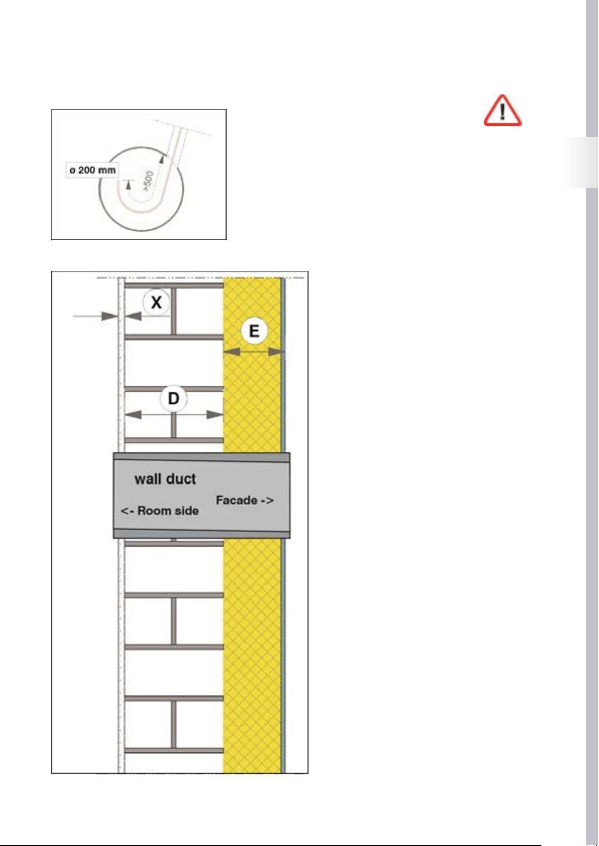
The units are also unable to be installed in cellar rooms with light shafts, since it is possibility that the outgoing air is recirculated. When
the units are installed on a façade there needs to be a minimum distance of 1.2 m between individual units in order to avoid recirculation.
We recommend not using the unit in a location on the building that is exposed to the wind with a average wind speed of more then 5 m/s.
To prevent the ventilation units from causing inconvenience draughts, they should not be positioned directly next to people who are a
longer time in one place (seating, beds). Make sure that the flow of air into the room is not obstructed by furniture or curtains

R
4
3. DELIVERYUNITS/DELIVERYCONTENTS
A complete Fox up ventilation unit consists of an EPS wall duct and a fan unit for insertion into the wall duct. The fan unit
consists of a reversible fan (12 V/DC) and a ceramic heat accumulator for heat recovery.
Air is fed into the room through a design plate with filter insert, and carried to the outside through a weatherproof protective
hood.
The unit is operated via an electronic control system with control panel, and up to six ventilation units (3 x delivery, 3 x
extraction) can be controlled by the electronic control system. The electronic system is installed in a double-cavity wall box for flush-moun-
ted fitting.
The following delivery units are available for the various installation steps:
• Foxup-GP-Design, item no. 1145200: basic package consisting of wall duct (500 mm long), fan unit, inner plate, weatherproof protec-
tive hood and electronic control system with hollow-wall flush-mounted box.
• Foxup-EP-Design, item no. 1145201: supplementary package consisting of wall duct (500 mm long), fan unit, inner plate and weather-
proof protective hood.
• Foxup-Shellset500mm, item no. 1145210: shell set consisting of wall duct (500 mm long) and hollow-wall flush-mounted box.
• Foxup-Shellset1000mm, item no. 1145211: shell set consisting of wall duct (1000 mm long) and hollow-wall flush-mounted box.
• Foxup-Shellset500mm,item no. 1145212: shell set consisting of wall duct (500 mm long)
• Foxup-Shellset1000mm, item no. 1145213: shell set consisting of wall duct (1000 mm long)
• FoxupFMS-GP-Design, item no. 114220: final assembly basic package consisting of fan unit, inner plate, weatherproof protective
hood and electronic control system.
• FoxupFMS-EP-Design, item no. 1145221: final assembly supplementary package consisting of fan unit, inner plate, weatherproof
protective hood and electronic control system.
Foxupventilationunitcomplete
1. Weatherproofprotectivehood(air inlet/outlet opening on outside)
2. EPSwallduct
3. Designvalve(air inlet/outlet opening on room side)
4. Fanunit (incl. ceramic heat accumulator and filter insert)
5. Controlpanel/electroniccontrolsystem

5
EN
4. DIMENSIONS/TECHNICALDATA
4.1 DimensionsFoxupventilationunit -alldimensionsinmm-
Fox up inner plate
Fox up electronic control system Fox up inner plate
4.2 TechnicalData
Foxup ventilationunit
Airflow: 15 / 30 / 40 m³/h
Efficiency of heat exchanger: <91 %
Supply voltage : 230 V/50 Hz
Power consumption : 1,4 / 2,6 / 3,7 W
Sound pressure level : 19 / 24 / 341 dB(A)
Filter class : G2
Permissible operating temperature: -20 tot +40 °C
IP protection class: 20
Weight: 5,5 kg
ø of wall duct (inner / outer): 153 / 198 mm
Length of wall duct: 500² / 1000³ mm
1. Sound pressure level, factory measurement
2. Fox up shell set 500 mm
3. Fox up shell set 1000 mm

R
6
5. SELECTINGINSTALLATIONSITE
When selecting the installation position, pay
attention to the outer wall of the building, the units
needs to be positioned esthetical correct in the
building façade. For example: the units should be
installed at the same height as the windows and at equal distances
from windows.
The outside or room-side air inlet/outlet opening is recommended
at a minimum distance of 150 to 200 mm from adjacent façade
components and room corners!
Fox up ventilation units should be installed at a height of 1.6 to 1.8
m above the finished floor level, and the room-side air inlet/outlet
opening must not be covered by furniture or curtains.
6. INSTALLATIONOFWALLDUCT
EPS pipe wall duct
Inner ø 153, outer ø 198 mm, built-in gradient to outside (condensate drainage)
Wall ducts are available in two different lengths for Fox up ventilation units:
•Pipelength500mm: Fox up shell set 500 mm, item no. 1145210 or 1145212
•Pipelength1000mm: Fox up shell set 1000 mm, item no. 1145211 or 1145213
The delivery units Foxup-GP-Designand Foxup-EP-Designare supplied as standard with 500 mm wall ducts, the wall ducts are manu-
factured with a built-in gradient to the outside for condensate drainage (observe marking of outside, see fig. above).

7
EN
6.1 Tapholedrillingforwallduct
Create a hole with a diameter of 200 mm.
Feed the fan connecting lead (min. 3 x 0.25 mm2) into the wall duct.
The fan connecting lead must be perpendicular to the axe of the wall duct.
6.2 Installationofwallducts
Determine the overall thickness of the wall structure from
the dimensions of:
- The work measurement (D)
- The outside (E) (e.g. heat insulation + plaster)
- The inside (X) (e.g. plaster + tiles).
- The minimal length might never be shorter then 240 mm
Slide the wall duct into the wall opening, observing the
gradient to the outside / the room-side marking of the wall
duct. Allow the wall duct to stand perpendicular on the
both room and façade sides in accordance with the above
calculation.
Attention:
To ensure good movement of the fan / heat unit in the
wall duct, deformations of the wall duct due to external
pressure/tension should be avoided!

R
8
6.3 Wallductforinsertionofconnectingleadofventilationunit
Feed the electric connecting lead of the ventilation unit (see
view from
room side) into the wall duct.
Check the correct position of the wall duct (overhangs
outside / inside) and close the openings of the wall duct with
the protective covers.
Finally, fill the cavities (if any) between the wall opening and
the wall duct with non-pressurized
expanding foam.
7. INSTALLATIONOFELECTRONICCONTROLSYSTEM
The electronic control system of Fox up ventilation units
is designed to be installed in a double hollow cavity
flush-mounted box. It can be used to control up to six Fox
up ventilation units.
The electronic control system is to be connected as statio-
nary equipment with fixed wiring.
See page 9 for electrical connection diagram.
The supply voltage of the electronic control system is 230 V/50 Hz. A light-plastic sheathed cable 3 x 1.5 mm2 (e.g. NYM-J 3 x 1.5 mm2) is
recommended as an incoming line.
The ventilation units are supplied by 12 V DC in combination with a PWM controlling signal. Therefore, the ventilation units should not under
any circumstances be connected to the 230 V mains voltage of the electronic control system. A light-plastic sheathed cable 3 x 0.25 mm2
(e.g. LiYY 3 x 0.25 mm2) is recommended as a control line for the ventilation units with a maximum length of 10m.

9
EN
8. ELECTRICALCONNECTIONOFELECTRONICCONTROLSYSTEM/VENTILATIONUNIT
Theelectricalconnectionmustbecarriedoutaccordingthelocalapplicablestandard. Duringinstallation
andmaintenancework,allpolesmustbedisconnectedfromthemainswithacontactgapofatleast3mm.
Disconnectionsmustbeimmobilisedintheopenposition!
•Connectingtheelectroniccontrolsystem:
Connecting a single unit:
A single ventilation unit is connected to the
Unit 1 or Unit 2 plug-in connector as shown in
the figure on the left.
When connected to the Unit 1 plug-in
connector, the unit can be used in “summer
mode” (see Ventilation mode page 16) as
a delivery unit. When connected to the Unit
2 plug-in connector, the unit can be used in
summer mode as an extraction unit.
Connecting several units:
Several units may be connected in pairs to
the plug-in connectors Unit 1 – Unit 2, Unit 3 –
Unit 4, Unit 5 – Unit 6; when used in pairs.
One of the units in the pair operates in delivery
mode, and the second unit operates in extrac-
tion mode, with the air direction of both units
swapping in the next interval.
8.1 Connectingventilationunit(s)–electroniccontrolsystem
Fox up ventilation units are connected to the electronic control system via a plug-in connector supplied with the ventilation units as shown
above. Please observe polarity of delivery/extraction units (see fig. above)!

R
10
8.2 Electricalconnectionofexternalcontrolelements
The operating mode of Fox up ventilation units is set to user-dependently via the control panel of the electronic control
system. Different operating variants can be selected with different power stages.
By connecting optional external control elements, a time- or moisture-dependent unit mode can also be activated. External control
elements are connected as shown above via the “external inputs” connector to the electronic control system of the ventilation units. The
function of the unit when controlled externally is described from page 19 of these instructions.
Connectingexternalcontrolelements
A data line (e.g. 2 x 2 x 0.6 (e.g. J-Y(ST)Y) is recommended for connecting external control inputs (floating contacts).

11
EN
9. INSTALLATION
9.1 Installationoffanunit
After the electrical connection has been made, the fan unit, consisting of the heat accumulator and fan, is inserted into the
wall duct:
Carefully slide the fan unit (fan towards façade) into the wall duct,
making sure that the fan’s connecting lead is not trapped / damaged.
The strap on the heat accumulator allows the fan unit to be aligned
during installation and removed from the wall duct for maintenance
purposes. Next, connect the plug-in connector between the connecting
leads of the ventilation unit and control unit.
9.2 Finalassembly
Once the insulation and plastering work has been completed, the wall duct
must be adapted to the dimensions of the finished wall by being cut with a
Stanley knife or hot wire flush with the wall on both room and façade sides.
Next install the support frame for the internal plate (room side) and the
weatherproof protective hood (façade side) of the ventilation unit using the
mounting materials which are supplied with the ventilation unit.

R
12
To prevent water from entering the wall opening,
the façade-side transition between the wall duct and the
support frame for the weatherproof protective hood must be
sealed all round with silicone or some other suitable sealant!
Slide the filter insert (1) supplied with the ventilation unit into
the wall duct and close the inner plate (2) of the ventilation
unit (magnetic catch).
Finally, install the unit’s façade-side weatherproof protective
hood (3). The hood is clipped onto a lug on the top of the
support frame and attached to the bottom of the support frame
using the fastening screw as supplied (4).
9.3 Functionaltestofventilationunit(s)
Once installed, the function of the unit(s) must be checked. Before carrying out the check, make sure that the air passages of the venti-
lation unit(s) are free from assembly residues / foreign bodies and that all electrical work was carried out and completed in a technically
correct manner!
After switching on the power supply (generally via the electrical
installation’s automatic circuit-breakers), the ventilation unit can be
started using the electronic control system’s control panel. At start-up,
check all the unit functions as described at page 18 of the operating
instructions, making sure that the fan motor is running quietly and
smoothly.
Any malfunctions or faults found in the ventilation unit must be correc-
ted before the unit is finally put into operation. Possible causes of faults
and their rectification are described in the section entitled Malfunctions
(see page 22).
Document the properly performed installation / functional testing of the ventilation unit(s) in the start-up report on page 13 of these
installation instructions.

13
EN
10. START-UPREPORT
Building project:
Client:
Street:
Postcode / place:
Telephone:
E-Mail:
Ventilation unit(s) installed:
Type:
Number:
:
Fitter:
:
Installer:
Company:
Street:
Postcode / place:
Telephone:
E-Mail:
•Installationworkcompleted
•Electricalconnectioncarriedout/testedinatechnicallycorrectmanner
•Unitfunctionchecked
•Filterinsert(s)used
•Unitoperatorinstructed(operation,maintenance)
•Unitdocumentationhandedover(installation/operatinginstructions)
Optionwhenoperatingunitsinconjunctionwithheat-producingappliances:
•Safetydevicesinstalled/tested
Place:
Date:
Fitter:
Client:

R
14
11. OPERATINGINSTRUCTIONS
1. GENERALNOTES
Your Fox up ventilation unit allows you to create a healthy, pleasant indoor and ambient climate in your flat or house through
regulated, needs-based ventilation. Thanks to their easy installation and simple operation, the units are ideal for use in new
buildings and in case of refurbishment..
Fox up ventilation units are manufactured in accordance with the latest technological standards and acknowledged safety
regulations. General type approval has been applied for.
Please read these operating instructions carefully before using the unit, and follow the instructions during installation and during maintai-
ning the unit. The operator of the ventilation unit is responsible for the condition and proper operation of the unit, with due regard for the
aforesaid instructions. Improper use, incorrectly carried out repair or maintenance work and structural changes may adversely affect the
function and safety of the unit and invalidate any warranty claims.
Installation and work on the ventilation unit should only be carried out by speciallytrainedstaffin accordance with the regulations on
occupational safety and accident prevention.
Fox up ventilation units with heat recovery are designed for the airing and ventilation of one or more rooms. The units should only be
used to deliver air. The delivery of aggressive, flammable or dust-laden media is not permitted. Never operate the unit without the filter
inserted.
The connection of ventilation pipes / connection to other ventilation systems is not permitted. Fox up ventilation units are not suitable for
construction drying, and should only be used once construction work has finished.
Operating the unit in conjunction with heat-producing appliances may require additional safety devices (Fire Regulations). Relevant
information is available from your local chimney sweep.
Prerequisitesforoptimalventilation:
1. Where possible, keep doors and windows in the rooms being ventilated closed.
2. If several units are operated, overflow openings are to be provided between the rooms being ventilated (shortening of door
leaves, installation of door air grilles).
3. All ventilation units should be operated simultaneously in a ventilation setting as equal as possible.
1. General notes.......................................................................................................................................................................................................... 14
2. Unit description......................................................................................................................................................................................................15
3. Settings for ventilation mode...............................................................................................................................................................................16
4. Operating and display elements of electronic control system........................................................................................................................18
5. External control inputs for electronic control system.......................................................................................................................................19
6 . Cleaning / Maintenance of the ventilation unit.................................................................................................................................................20
7. Error messages / Malfunctions...........................................................................................................................................................................22
8. Maintenance report / Filter cleaning ..................................................................................................................................................................24

15
EN
2. UNITDESCRIPTION
The Fox up ventilation unit is a decentralized ventilation system for controlled room ventilation with heat recovery. The use of
several units in pairs allows entire housing units / buildings to be ventilated.
The ventilation unit consists of an EPS wall duct that can be cut to length for wall thicknesses up to 500 m (alternatively
1000 mm) and a fan unit inserted into the wall duct. The fan unit consists of a reversible van (12 V/DC) and a ceramic heat accumulator for
heat recovery.
Air is fed into the room through a white, powder-coated design plate with a filter insert (filter class G2), and is carried to the outside
through a white, powder-coated weatherproof protective hood.
The unit is operated via the control panel of a wired electronic control system for flush-mounted fitting, and up to six ventilation units (3 x
delivery, 3 x extraction) can be controlled by the electronic control system.
Foxupventilationunitcomplete
1. Weatherproofprotectivehood(airinlet/outletopeningonoutside)
2. EPSwallduct
3. Designvalve(airinlet/outletopeningonroomside)
4. Fan
5. Ceramicheataccumulator
6. Filterinsert
7. Controlpanel/electroniccontrolsystem

R
16
3. SETTINGSFORVENTILATIONMODE
3.1 Settingsforventilationmode
The operating variants of Fox up ventilation units are set using the control panel of the electronic control system of the venti-
lation units. Two basic functions with different fan powers can be set :
Summermodefunction ------->
Wintermodefunction------->
1. Summer mode function (delivery or extraction mode without heat recovery):
In this setting, the ventilation unit(s) work constantly in delivery* or extraction* mode, without heat recovery. *The operating mode
is defined by the electrical connection; the unit can be connected to the electronic control system as a delivery or extraction unit (see
Electrical connection page 9)
2. Winter mode function (delivery and extraction mode with heat recovery):
The ventilation unit(s) work alternately in 2 set time intervals. In the first interval (extraction phase), the “used” air in the room is suc-
ked into the ventilation unit and pushed to the outside. During this process, the air flows through the ceramic heat accumulator inside
the ventilation unit, which extracts the heat from the air and stores it.
In the second interval (delivery phase), “fresh” outside air is sucked into the ventilation unit. It passes through the unit, and is heated by
the heat accumulator before entering the room.
If the Fox up ventilation units are used in pairs, the units in a pair work in opposite directions, i.e. the first unit in delivery mode and the
• Fox up ventilation system with 3 delivery and 3 extraction units:

17
EN
3.2 Minimumventilationoption
To guarantee a permanent minimum ventilation, there is the option with Fox up ventilation units of setting a constant ventila-
tion mode at a minimum power stage. Depending on the setting, the ventilation unit(s) work in summer or winter mode. It is
not possible to switch off the unit using the electronic control system’s control panel.
The minimum ventilation is activated / deactivated by re-plugging a jumper on the back of the control panel of the electronic control sys-
tem. To activate the minimum ventilation, the control panel of the electronic control system must be detached (carefully remove control
panel), and the minimum ventilation is activated on the disconnected control panel as described below:
Attention:
Before changing the jumper position, all poles of the power supply to the ventilation unit must be disconnected. Disconnec-
tions must be immobilised in the open position!
< ---- alternative --->
If the jumper on the back of the control panel is
plugged in, the ventilation unit can be switched off
using the “down” arrow key (see fig. page 18).
Ventilation is interrupted, and the “unit off” signal
lamp (see fig. page 18) lights up.
If the jumper on the back of the control panel has
been removed or is only plugged into one pin, mini-
mum ventilation is activated. The ventilation unit is
not completely switched off using the “down” arrow
key (see fig. page 18), but runs continuously at a
minimum power stage.
The activated minimum ventilation is signaled by
the pulsing “unit off” signal lamp (see fig. page
18).

R
18
4. OPERATINGANDDISPLAYELEMENTSOFELECTRONICCONTROLSYSTEM
Pressing this key sets the unit to power stage 1. Pressing this key again selects the next power stage up.
Pressing this key switches the unit back to the next power stage down. If the unit is at power stage 1, pressing
this key again switches the unit off or returns it to minimum ventilation1.
1 minimum ventilation option, see page 17.
Pressing this key sets the unit to delivery or extraction mode2 without heat recovery (= summer mode). Summer
mode automatically switches back to winter mode, 8 hours after being activated. Pressing this key again
extends the summer mode by a further 8 hours.
2 depending on the electrical connection, see page 9.
Pressing this key sets the unit to alternate delivery/extraction mode with heat recovery (winter mode). During
the heating period, the device should be operated in this mode at all times.
If this symbol lights up, the unit is at power stage 1.
If this symbol lights up, the unit is at power stage 2.
AIf this symbol lights up, the unit is at power stage 3. Power stage 3 automatically switches back to power stage
2 one hour after being activated. If this symbol is flashing, the external moisture mode has been activated3.
3 External moisture mode option, see page 19.
If this indicator is permanently lit it indicates that the ventilation unit’s filter insert is due for inspection /
cleaning. The maintenance of the filter insert is described on page 20.
If this indicator is flashing it indicates a functional fault on the electronic control system’s control panel. The
electronic control system or the control panel must be checked by a qualified electrician, see error messages
page 22.
If this indicator lights up, the unit has been switched off via the “down” arrow key. Ventilation can be switched on
using the “up” arrow key.
If this indicator is pulsing, the unit has been switched to the “minimum ventilation” power stage via the “down”
arrow key (see page 17). The ventilation unit’s power stage can be increased using the “up” arrow key.
If this indicator is flashing, the unit has been switched off externally.
For External off option, see page 24.
Table of contents
Languages:
Popular Fan manuals by other brands

Patron
Patron FA-12 product manual

Lasko
Lasko CYCLONE 1825 user manual

Pinnacle Climate Technologies
Pinnacle Climate Technologies MASTER MAC-310A-120 instruction manual

Westinghouse
Westinghouse Carolina LED owner's manual

iGenix
iGenix DF2900 Instructions for use

INTO DAALDEROP
INTO DAALDEROP HRU ECO 350 user manual