5
LE D S c r e e n
A1 A2 A3 A4 B2
B1
LE D S c r e e n
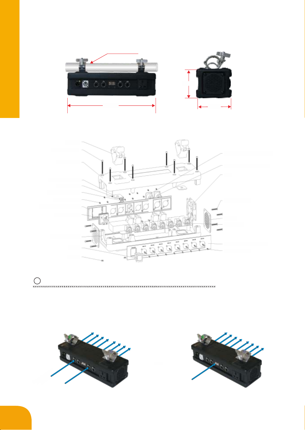
Main signal:A1
Signal Distribution Signal Hot backup
Example 1
3Function Introduction of Signal Divider
3.1 Signal Transformation
Use the optical fiber cable to arrive the optical signal from controller to transform as network signal
which makes signal transmission distance can be up to 10 kilometers.
3.2 Signal Distribution:
Signal divider can display the signal from controller segment. Each port can control one column (row) or
several columns (rows) LED screen as shown below picture, for detailed application see the later example 2,:
Backup signal:A2
3.3 Signal Hot Backup
Some of the signal divider port as the main signal input, others as the backup signal input, it makes the
screen has two channels input signals in real time at working .When one signal interrupted, another signal
will proceeded automatically , so as to guarantee the system's signal more stable. But the signal address of
the main signal and backup signal is reverse. For details stetting method please see the first example.
For the signal hot backup schemes,there is one LED screen, Port A1 as the main signal input port and
connect to the first LED panel's input, Port A2 as the backup signal input port and connect to the last LED
panel's output. Thereby ensuring there are main signal and backup signal on the screen at the same time.
4Application Example
Application Example 1: Hot backup signal function and address setting for signal divider (SDV08)
For example: LED screen IDsn3. size : 4mx3m , 8Column×6 Row ,
Requirement: Use Signal divider,included main signal and backup signal in this project. Below is the
detailed setup method and procedure. one LED panel(box) pixels density is 128×128 points and size is
0.5m×0.5m.
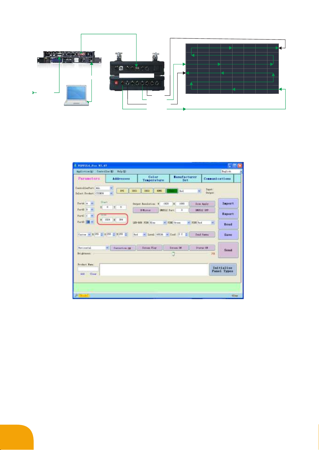
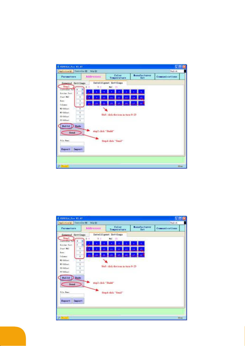
Step1: Analysis
We can calculate the resolution of the LED screen is 1024×768 according to the screen size. Port 1 and
Port 2 should be used according to the signal segmentation way of controller.
Transmit the signal from the optical port OUT1 of controller to the optical port of signal divider (You can
also use the network port OUT1 and OUT2 transmit the signal to port SIG A and SIG B). Signal divider port
A1/B1 as the main signal port of OUT1/OUT2 ,A2 /B2 as the backup signal port of OUT1/OUT2.
OUT1control the upper portion of the LED screen (8 columns and 3 rows of the top screen) OUT2 control
the lower portion of the LED screen (8 columns and 3 rows of the bottom screen)
The resolution of the LED screen whose size is 8 columns and 3 rows is 1024×384, so W=1024 and
H=384 in the control software.
Detailed connection diagram shown as follows: