Sentencia Eco User manual

OM-ENG-SentenciaEco-Rev2010.10
O
OW
WN
NE
ER
R'
'S
S
M
MA
AN
NU
UA
AL
L
Eco &Eco+
WATER SOFTENER SYSTEM
TABLE OF CONTENT & INSTALLATION RECORD
Page 2
Table of Content & Installation Record ...............................................................................Page 2
Warning & Safety Instructions.............................................................................................Page 3
Operating Conditions & Requirements ..............................................................................Page 4
Installation ...........................................................................................................................Page 5
Start-Up................................................................................................................................Page 7
Electronic Control Panel ......................................................................................................Page 8
Maintenance........................................................................................................................Page 10
Troubleshooting...................................................................................................................Page 12
Technical Specification Sheet - Eco .....................................................................................Page 14
Technical Specification Sheet - Eco+....................................................................................Page 15
Notes....................................................................................................................................Page 16
For future reference, fill in the following data
INSTALLATION RECORD
Serial Number: _______________________________________________
Model: ________________________________________________________
Water Hardness inlet: _______________________________________
Water Hardness outlet: _____________________________________
Water Pressure inlet: ________________________________________
Date of Installation: __________________________________________
Company Name: _____________________________________________
Installer Name: _______________________________________________
Phone Number: ______________________________________________

WARNING & SAFETY INSTRUCTIONS
Page 3
Before you begin the installation of the water softener, we advise
you read and carefully follow the instructions contained in this
manual. It contains important information about safety, installation,
use and maintenance of the product. The actual system that you
have received, may differ from the pictures/illustrations in this
Owner's Manual.
Failure to follow the instructions could cause personal injury or
damage to the appliance or property. Only when installed,
commissioned and serviced correctly, the water softener will offer
you many years of trouble-free operation.
The water softener is intended to 'soften' the water, meaning it will
remove hardness minerals; it will not necessarily remove other
contaminants present in the water. The water softener will not purify
polluted water or make it safe to drink!
Installation of the water softener should only be undertaken by a
competent person, aware of the local codes in force. All plumbing
and electrical connections must be done in accordance with local
codes.
Before setting up the water softener, make sure to check it for any
externally visible damage; do not install or use when damaged.
Use a hand truck to transport the water softener. To prevent
accident or injury, do not hoist the water softener over your
shoulder. Do not lay the water softener on its side.
Keep this Owner's Manual in a safe place and ensure that new users
are familiar with the content.
The water softener is designed and manufactured in accordance with
current safety requirements and regulations. Incorrect repairs can
result in unforeseen danger for the user, for which the manufacturer
cannot be held responsible. Therefore repairs should only be
undertaken by a competent technician, familiar and trained for this
product.
In respect of the environment, this water softener should be
disposed of in accordance with Waste Electrical and Electronic
Equipment requirements. Refer to national/local laws and codes for
correct recycling of this water softener.

OPERATING CONDITIONS & REQUIREMENTS
Page 4
OPERATING PRESSURE: min. 1,4 / max. 8,3 bar
check water pressure regularly.
take into account that night time water pressure may be
considerably higher than day time water pressure.
install a pressure reducer ahead of the water softener if
necessary.
OPERATING TEMPERATURE: min. 2 / max. 48 °C
do not install the water softener in an environment where
high ambient temperatures (e.g. unvented boiler house) or
freezing temperatures can occur.
the water softener cannot be exposed to outdoor
elements, such as direct sunlight or atmospheric
precipitation.
do not install the water softener too close to a water
heater; keep at least 3 m of piping between the outlet of
the water softener and the inlet of the water heater; water
heaters can sometimes transmit heat back down the cold
pipe into the control valve; always install a check valve at
the outlet of the water softener.
ELECTRICAL CONNECTION: 230V-50Hz
this water softener only works on 24VAC; it is equipped
with a 230/24V-50Hz transformer; always use it in
combination with the supplied transformer.
make sure to plug the transformer into a power outlet,
which is installed in a dry location, with the proper rating
and over-current protection.
INSTALLATION
Page 5
To facilitate the installation process, remove the salt lid and main cover from the water softener.
INLET & OUTLET
Check the water pressure at the place of installation
of the water softener; it should never exceed 8,3 bar.
In case of high concentration of impurities in the inlet
water, we recommend the installation of a sediment filter,
ahead of the water softener.
We strongly recommend the use of flexible hoses to
connect the water softener to the water distribution
system; use hoses with a large diameter in order to limit
the pressure loss.
If the water softener is not equipped with the factory
bypass (optional), we strongly recommend to install a 3-
valve bypass system (not included with this product!) to
isolate the water softener from the water distribution
system in case of repairs. It allows to turn off the water to
the water softener, while maintaining (untreated) water
supply to the user.
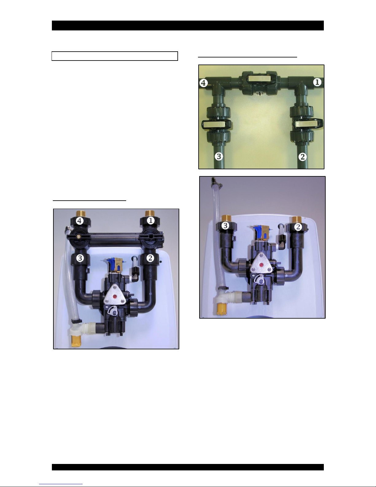
WITH FACTORY BYPASS (optional)
= mains water supply (untreated water)
= inlet of water softener (untreated water)
= outlet of water softener (treated water)
= house/application (treated water)
1. Screw the factory bypass onto the elbow connections
of the water softener (&); make sure to install the
gasket seals. Tighten the nuts firmly by hand.
2. Screw the brass connection kit with nuts onto the
factory bypass (&); make sure to install the
gasket seals. Tighten the nuts firmly by hand.
3. Connect the mains water supply to the brass nipple
on the inlet port of the factory bypass ().
4. Connect the house/application to the brass nipple on
the outlet port of the factory bypass ().
WITH 3-VALVE BYPASS SYSTEM (not included)
= mains water supply (untreated water)
= inlet of water softener (untreated water)
= outlet of water softener (treated water)
= house/application (treated water)
1. Install the 3-valve bypass system.
2. Screw the brass connection kit with nuts onto the
elbow connections of the water softener (&);
make sure to install the gasket seals. Tighten the nuts
firmly by hand.
3. Connect the 3-valve bypass system to the brass
nipples on the elbow connections (&).
4. Connect the mains water supply to the inlet of the 3-
valve bypass system ().
5. Connect the house/application to the outlet of the 3-
valve bypass system ().

INSTALLATION
Page 6
DRAIN
We recommend the use of a stand pipe with air trap.
To prevent backflow from the drainage system into
the water softener, always make sure to have an air gap
between the end of the drain line and the drainage system
itself; as a rule of thumb, the air gap should be minimum
2x the diameter of the drain line.
Always use separate drain lines for the control valve
(evacuation of rinse water) and the softener cabinet's
overflow.
Lay-out the drain hoses in such a way that pressure
loss is minimized; avoid kinks and unnecessary elevations.
1. Connect a 13 mm hose to the drain solenoid of the
control valve (); secure it by means of a clamp.
2. Run the drain hose to the drainage system and
connect it to the stand pipe assuring sufficient air
gap. This drain line operates under pressure, so it may
be installed higher than the water softener.
3. Connect a 13 mm hose to the overflow elbow, located
at the back side of the water softener; secure it by
means of a clamp.
4. Run the drain hose to the drainage system and
connect it to the stand pipe assuring sufficient air
gap. This drain line does NOT operate under pressure,
so it may NOT be installed higher than the water
softener.
ELECTRICAL
1. Plug the transformer into an electrical outlet.
2. Plug the transformers output lead into the socket on
the water softeners power cord; secure it by means
of the clamp.
START-UP
Page 7
PRESSURIZING
1. Put the bypass system in 'bypass' position.
2. Make sure the electronic controller of the water
softener is 'in service'.
3. Open the mains water supply.
4. Open a cold treated water faucet nearby the water
softener and let the water run for a few minutes until
all foreign material that may have resulted from the
installation is washed out; close the tap.
5. Gently pressurize the water softener, by putting it
into service:
factory bypass:
1. open the 'outlet' valve;
2. slowly open the 'inlet' valve.
3-valve bypass:
1. close the 'bypass' valve;
2. open the 'outlet' valve;
3. slowly open the 'inlet' valve.
6. After 2-3 minutes, open a cold treated water faucet
nearby the water softener and let the water run for a
few minutes until all air is purged from the
installation; close the tap.
7. Check the water softener and all hydraulic
connections for leaks.
BRINE CABINET
8. Add water conditioner salt to the brine cabinet.
ELECTRONIC CONTROL PANEL
9. Program the electronic controller (refer to section
'ELECTRONIC CONTROL PANEL').
INITIATE A REGENERATION
10. Manually initiate a regeneration, by pressing the
scroll button repeatedly until the display shows:
11. Leave the water softener in this position; the
countdown timer will countdown to 0 sec and start a
regeneration.
Regen in 10 sec

ELECTRONIC CONTROL PANEL
Page 8
display
POWER led: lights up when electrical power is
applied
DOWN button: to decrease the value of the
parameter
UP button: to increase the value of the parameter
SCROLL button: to advance to the next
parameter
POWER-UP
After power-up, the display will show the installed
software version for 5 seconds, f.e.:
Afterwards it will automatically revert back to the service
display.
The POWER led will light up.
POWER FAILURE
In the event of a power failure, the program will remain
stored in the NOVRAM® during an undefined period, while
an incorporated SuperCap (capacitor) will maintain the
correct time of day during a period of several hours;
consequently, in case of prolonged power failure, the time
of day might not be maintained; if this happens, the time
of day indication will flash when the power supply is re-
established, indicating that the time of day needs to be
set.
When the power failure occurs during the execution of an
automatic regeneration, the control valve will immediately
return to the service position; when the power supply is re-
established, the control valve will stay in the service
position for 60 sec. and restart a complete regeneration
from the beginning.
TIMER FAILURE
In the event of a timer failure, the display will show the
message:
In such case, entering one of the programming levels can
possibly solve the problem. However if the problem
persists, professional service is required.
SERVICE MODE
In service mode the display shows the time of day and the
remaining number of days:
REGENERATION MODE
In regeneration mode the display shows the actual
regeneration cycle and, where relevant, the total
remaining regeneration time and remaining cycle time:
The control valve can be reset to service mode at any time
by pressing the scroll button, as such manually
advancing it through the regeneration cycles.
CHECKING THE FLOW METER
In case of water usage, the remaining capacity counter in
the service display will count back per unit, i.e. per litre;
furthermore the water usage indicator will revolve. This
way the correct functioning of the water meter can be
verified.
MANUAL REGENERATION
It is possible to manually initiate a regeneration.
1. Press the scroll button repeatedly until the display
shows:
If the control valve is left in this position, the
countdown timer will countdown to 0 sec and
start a regeneration.
To cancel this mode, press the scroll button
before the countdown timer has reached 0 sec;
the control valve will return to the service mode.
Service Required
EU4PB
Regen in 10 sec
20:51 1000L -
BRINE FILL
Regen Pending
Rgn:XXX CycY:ZZZ
ELECTRONIC CONTROL PANEL
Page 9
PROGRAMMING INSTRUCTIONS
Before entering the programming mode, make sure that
the control valve is in the service mode.
1. Press the scroll button; the display will show:
Press the up button or down button to set
the language.
2. Press the scroll button again; the display will show:
Press the up button or down button to set
the time of day.
3. Press the scroll button again; the display will show:
Press the up button or down button to set
the hardness of the incoming untreated water.
Language:English
Set time: 20:51
Set hardn.: XX°f
MAINTENANCE
Page 10
BYPASSING THE WATER SOFTENER
Occasionally it may be necessary to put the unit
hydraulically in bypass, i.e. to isolate it from the water
distribution system; f.e.:
in case of an urgent technical problem with the water
softener;
when the water softener needs to be removed for
maintenance;
when it is not necessary to supply treated water to
the house/application (refill swimming pool,
irrigation,...).
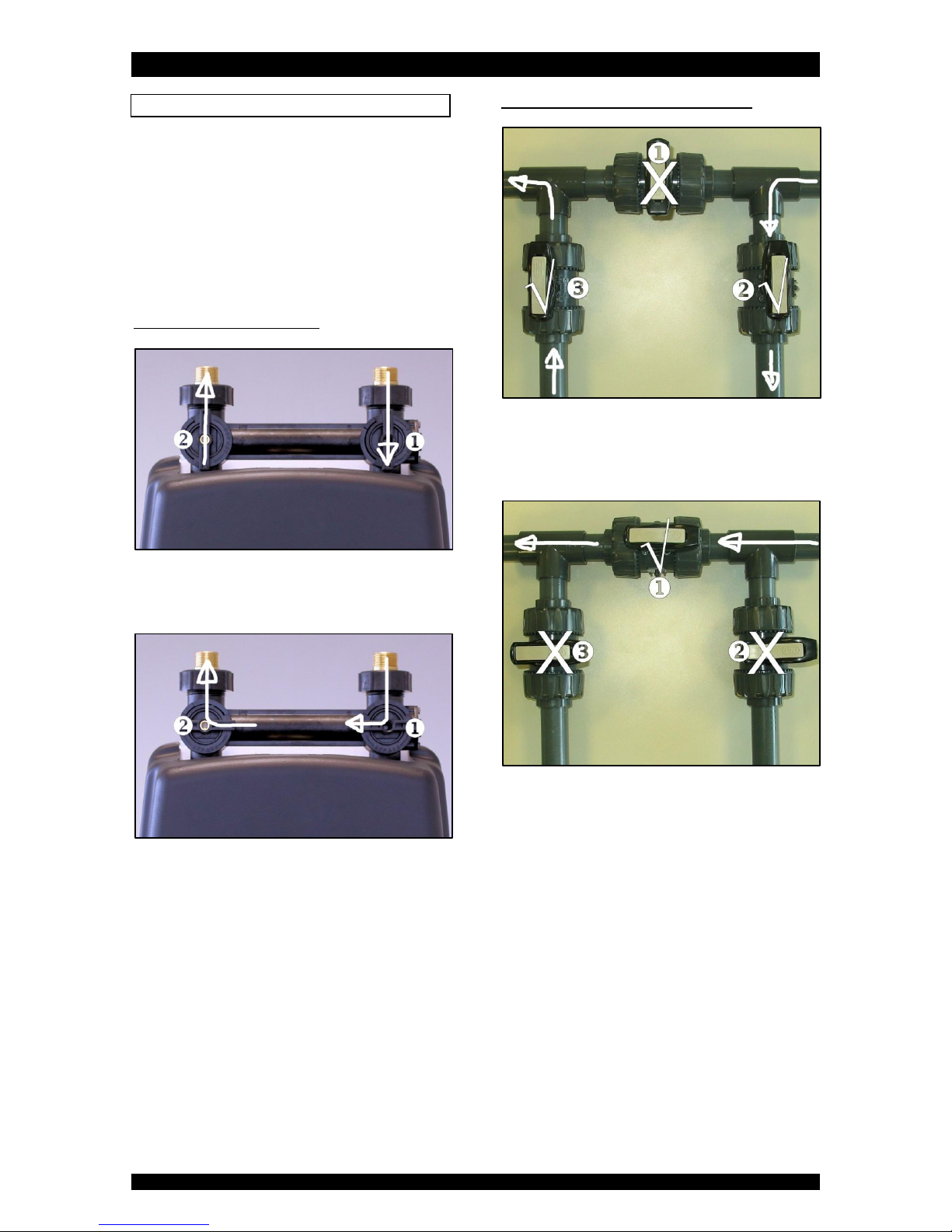
WITH FACTORY BYPASS (optional)
SERVICE POSITION
= inlet valve to water softener is OPEN
= outlet valve from water softener is OPEN
BYPASS POSITION
= inlet valve to water softener is CLOSED
= outlet valve from water softener is CLOSED
WITH 3-VALVE BYPASS SYSTEM (not included)
SERVICE POSITION
= bypass valve is CLOSED
= inlet valve to water softener is OPEN
= outlet valve to water softener is OPEN
BYPASS POSITION
= bypass valve is OPEN
= inlet valve to water softener is CLOSED
= outlet valve to water softener is CLOSED

MAINTENANCE
Page 11
WATER CONDITIONER SALT
The water softener needs 'brine' for its periodic
regenerations. This brine solution is made from water, that
is automatically dosed in the brine cabinet by the control
valve, and water conditioner salt.
The user should make sure that the brine cabinet is always
kept full of water conditioner salt. Therefore he should
periodically check the salt level inside the brine cabinet
and refill it if necessary. To open the salt lid, simply take it
by the handle and lift it. The salt lid can be removed
completely to facilitate refilling.
Ideally the level of water conditioner salt inside the brine
cabinet is kept between 1/3 and 2/3. A lower level of
water conditioner salt can cause insufficient brine
saturation, resulting in a loss of softening capacity. A
higher level of water conditioner salt can cause salt
bridging (hard crust or salt bridges in the brine cabinet).
When you suspect salt bridging:
1. carefully pound on the outside of the brine cabinet to
break loose the salt bridges;
2. using a broom (or like blunt tool) carefully push the
salt to break it apart;
3. pour warm water over the top of the salt to dissolve
it.
BRINE CABINET
To retain the appearance of the water softener, simply
wipe it with a damp cloth or clean it with a mild soap
solution; never use abrasive cleaners, ammonia or
solvents.
RESIN CLEANER
Other contaminants (f.e. iron) present in the feed water
can cause the resin bed to foul up, resulting in a loss of
softening capacity. An approved resin cleaner can be used
periodically to thoroughly clean the resin bed.
SANITIZING THE WATER SOFTENER
This water softener is manufactured from premium quality
material and assembled in safe conditions to assure it is
clean and sanitary. If installed and serviced correctly, this
water softener will not infect or contaminate your water
supply.
However, as in any 'device' plumbed-in in your water
distribution system, a proliferation of bacteria is possible,
especially in case of 'stagnant water'. As this is a time-
controlled water softener, it will automatically rinse the
resin bed periodically, even in case of low or absence of
water usage.
If the power supply to the water softener is disconnected
for a longer period of time, we recommend, when the
power supply is re-established, to manually initiate a
complete regeneration (refer to section 'ELECTRONIC
CONTROL PANEL').

TROUBLESHOOTING
Page 12
PROBLEM
CAUSE
SOLUTION
Hard (untreated) water
to service
Open or defective bypass
Close or replace bypass
Water softener in regeneration
Wait until regeneration finishes or manually
advance regeneration to end
No salt in brine cabinet
Add salt and initiate regeneration manually
Salt bridging
Break salt bridge(s) and initiate regeneration
manually
Change in raw water hardness
Measure the hardness of the incoming
untreated water and adjust programming
accordingly
Water softener fails to start a regeneration
Refer to problem “Water softener fails to start
a regeneration”
Control valve fails to draw brine
Refer to problem “Valve fails to draw brine”
Decreasing exchange capacity of resin
Clean or replace resin bed
Loss of resin
Refer to problem “Loss of resin”
Leak at riser tube
Verify that riser tube is seated correctly and is
not cracked
Residual hardness in
treated water
Bypass not completely closed
Close bypass
Water softener fails to
start a regeneration
Faulty electrical supply
Verify electrical service (fuse, transformer,...)
Defective flow meter
Clean and/or replace flow meter
Defective PCB
Replace PCB
Defective drain solenoid
Replace drain solenoid
Body stem assembly switches continuously
Check operating pressure; must exceed 1,4 bar
Water softener uses
too much salt
Excessive water in brine cabinet
Refer to problem “Excessive water in brine
cabinet”
Unit regenerates too frequently
Verify program
Excessive water in
brine cabinet
Control valve fails to draw brine
Refer to problem “Control valve fails to draw
brine”
Improper brine refill time setting
Verify that brine refill time corresponds to the
proper salt level and amount of resin
Missing brine refill flow control
Verify that flow control is installed and
properly sized
Leak from control valve to brine cabinet
Clean or replace plunger and solenoid
diaphragm of refill solenoid
Salt taste in treated
water
Excessive water in brine tank
Refer to problem “Excessive water in brine
tank”
Injector undersized
Verify injector selection
Improper brine/slow rinse time setting
Verify that brine/slow rinse time corresponds
to the proper salt level and amount of resin
Loss of water pressure
Mineral or iron build-up in resin tank
Clean resin bed and control valve; increase
regeneration frequency
Plugged lower and/or upper distributor
Verify that distributors are free of debris
Crushed lower and/or upper distributor
Replace distributor(s)
Drain line from control
valve flows
continuously
Water softener in regeneration
Wait until regeneration finishes or manually
advance regeneration to end
Drain solenoid stuck in open position
Clean drain solenoid
Defective PCB
Replace PCB
Drain line from brine
cabinet overflow flows
continuously
Excessive water in brine cabinet
Refer to problem “Excessive water in brine
cabinet”
Leak between control valve and pressure tank
Verify seal between control valve and pressure
tank
Control valve fails to
refill brine tank
Improper brine refill time setting
Verify that refill time corresponds to salt level
and amount of resin
Plugged refill flow control
Clean flow control
Loss of resin
Lower and/or upper distributor damaged
Replace distributor(s)
Leak between riser tube and upper distributor
Verify that riser tube is seated correctly and is
not cracked
TROUBLESHOOTING
Page 13
PROBLEM
CAUSE
SOLUTION
Valve fails to draw
brine
Low operating pressure
Check operating pressure; must exceed 1,4 bar
Drain flow adjuster closed too much
Open drain flow adjuster slowly until unit
draws brine
Plugged injector and or brine restrictor
Clean injector and or brine restrictor
Plugged injector filter
Clean injector filter
Restricted drain line
Verify drain line for kinks or restrictions
Restricted brine line
Verify brine line for kinks or restrictions
Leak in brine line
Verify brine line and connections for air
leakage
No water in brine tank
Refer to problem “Control valve fails to refill
brine tank”
Backwash solenoid remains open
Verify solenoid membrane and plunger

TECHNICAL SPECIFICATION SHEET - Eco
Page 14
Technical specifications:
Model
Eco
Resin
11
15
20
26
32
Operating pressure min/max (bar)
1,4/8,3
Operating temperature min/max (°C)
2/48
Electrical connection (V/Hz)
230/50(1)
Maximum power consumption (VA)
17
Hydraulic connection inlet/outlet
¾” BSP Male
Control valve type
541N89
Control valve injector
8
8
5
5
5
Pressure tank dimensions (in)
9x18
9x24
10x24
9x35
10x35
(1) Supplied with 24 V transformer
Performances @ brining of 125gr/Ltr of resin(2):
Model
Eco
Resin
11
15
20
26
32
Nominal exchange capacity (m³x°f)
56
77
102
133
163
Nominal exchange capacity (m³x°d)
32
44
58
75
93
Salt usage per regeneration (kg) (3)
1,4
1,9
2,5
3,3
4,0
Exchange capacity per kg salt (m³x°f)
41
Exchange capacity per kg salt (m³x°d)
23
Recommended maximum service flow (m³/hr)
1,1
1,5
2,0
2,6
3,2
Rinse water usage per regeneration (@ 3 bars) (Ltr) (3)
59
80
92
116
141
(2) Indicative numbers, performances depending on operating conditions and water quality
(3) Maximum salt/water usage as brining is proportional (minimum of 60%)
Dimensions and weights:
Model
Eco
Resin
11
15
20
26
32
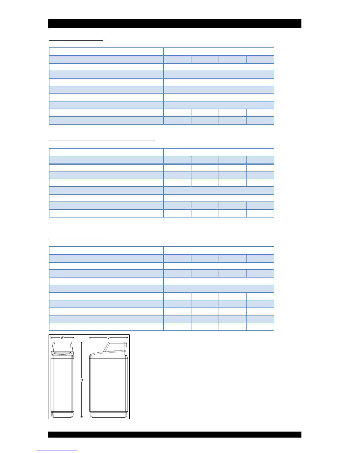
Width (mm) (W)
345
Height (mm) (H)
686
826
826
1.105
1.105
Depth (mm) (D)
573
Depth, including bypass (mm)
658
Height inlet/outlet (mm) (H2)
514
654
654
933
933
Height inlet/outlet, including bypass (mm)
520
660
660
939
939
Weight (kg)
18,5
24,0
28,5
35,5
41,0
Weight, including bypass (kg)
19,0
24,5
29,0
36,0
41,5
Maximum salt storage capacity (kg)
50
75
75
125
125
TECHNICAL SPECIFICATION SHEET - Eco+
Page 15
Technical specifications:
Model
Eco+
Resin
11
15
20
26
Operating pressure min/max (bar)
1,4/8,3
Operating temperature min/max (°C)
2/48
Electrical connection (V/Hz)
230/50(1)
Maximum power consumption (VA)
21
Hydraulic connection inlet/outlet
¾” BSP Male
Control valve type
541N84
Control valve injector
8
8
5
5
Pressure tank dimensions (in)
9x18
9x24
9x35
10x35
(1) Supplied with 24 V transformer
Performances @ brining of 125gr/Ltr of resin(2):
Model
Eco+
Resin
11
15
20
26
Nominal exchange capacity (m³x°f)
56
77
102
133
Nominal exchange capacity (m³x°d)
32
44
58
75
Salt usage per regeneration (kg) (3)
1,4
1,9
2,5
3,3
Exchange capacity per kg salt (m³x°f)
41
Exchange capacity per kg salt (m³x°d)
23
Recommended maximum service flow (m³/hr)
1,1
1,5
2,0
2,6
Rinse water usage per regeneration (@ 3 bars) (Ltr) (3)
97
118
149
185
(2) Indicative numbers, performances depending on operating conditions and water quality
(3) Maximum salt/water usage as brining is proportional (minimum of 60%)
Dimensions and weights:
Model
Eco+
Resin
11
15
20
26
Width (mm) (W)
345
Height (mm) (H)
686
826
1.105
1.105
Depth (mm) (D)
573
Depth, including bypass (mm)
658
Height inlet/outlet (mm) (H2)
514
654
933
933
Height inlet/outlet, including bypass (mm)
520
660
939
939
Weight (kg)
19,0
24,0
30,5
36,5
Weight, including bypass (kg)
19,5
24,5
31,0
37,0
Maximum salt storage capacity (kg)
50
75
125
125

NOTES
Page 16


Table of contents
Popular Water Filtration System manuals by other brands


Jet
Jet AFS-500 operating instructions

Flexit
Flexit Nordic S2 manual

Evolution Aqua
Evolution Aqua Tempest instruction manual

Waterman
Waterman SF 122 Operating and assembly instructions

Pentair
Pentair Everpure Coldrink - 7CLM+ Series Installation and operation guide

Kessel
Kessel 99601.002B Installation and operating instructions