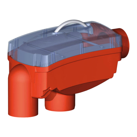
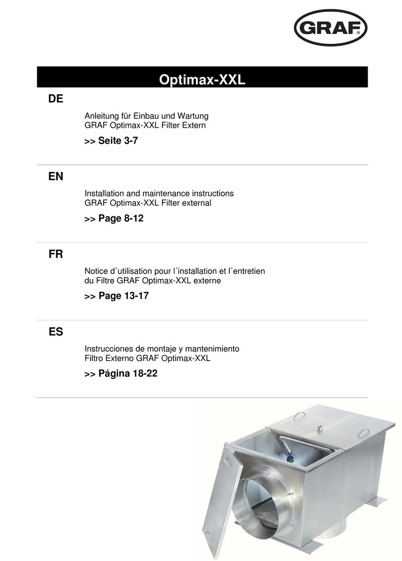
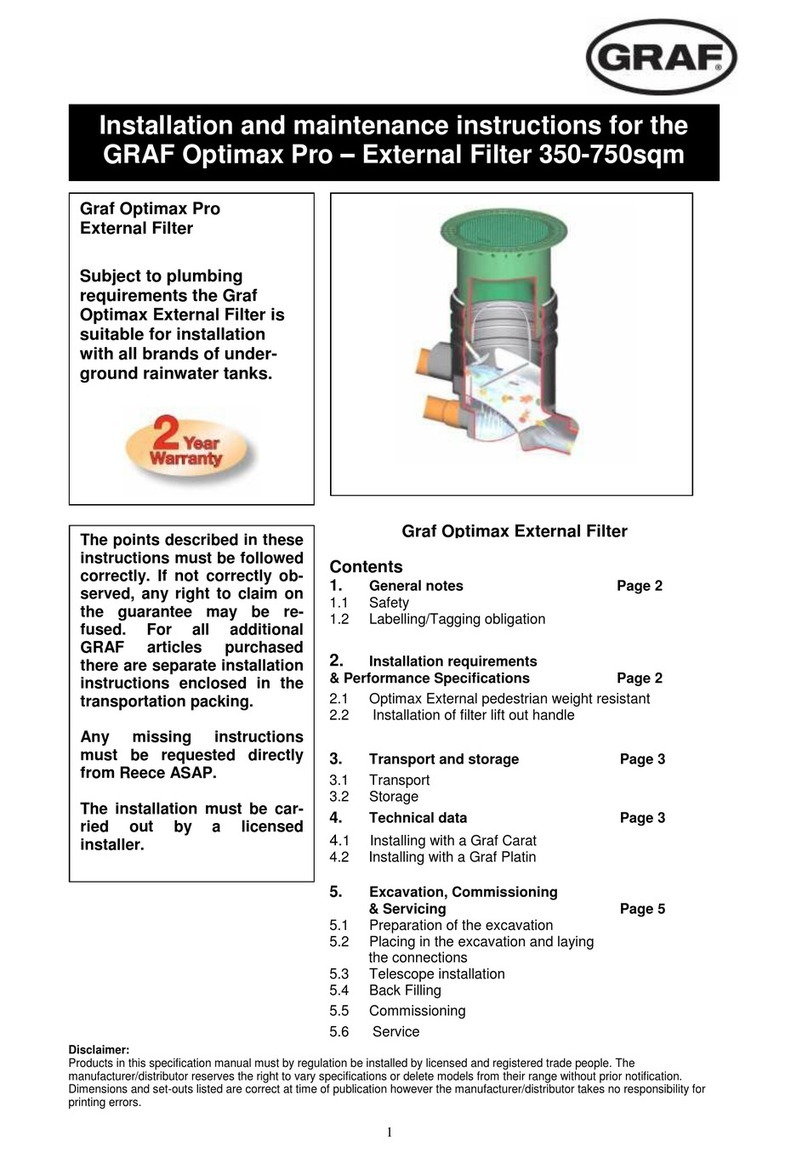
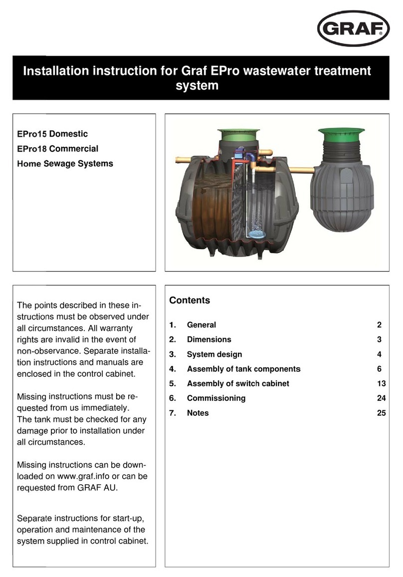
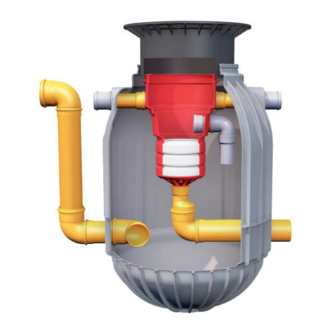
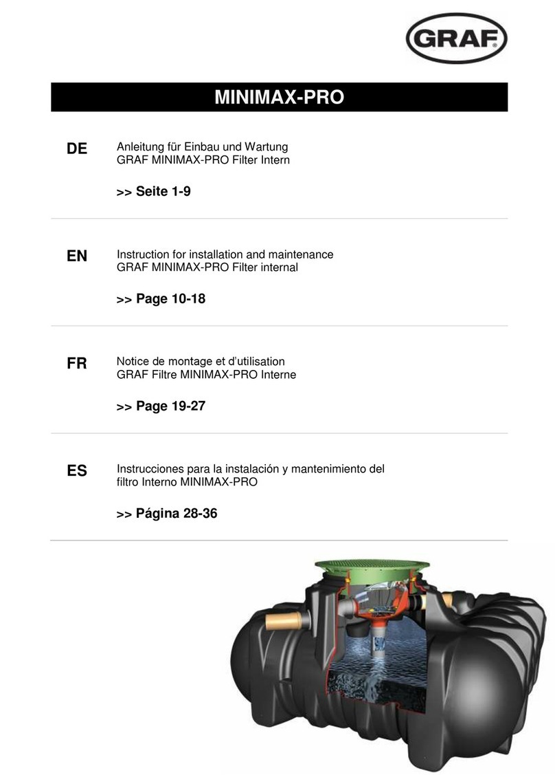
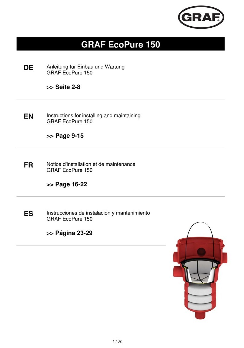
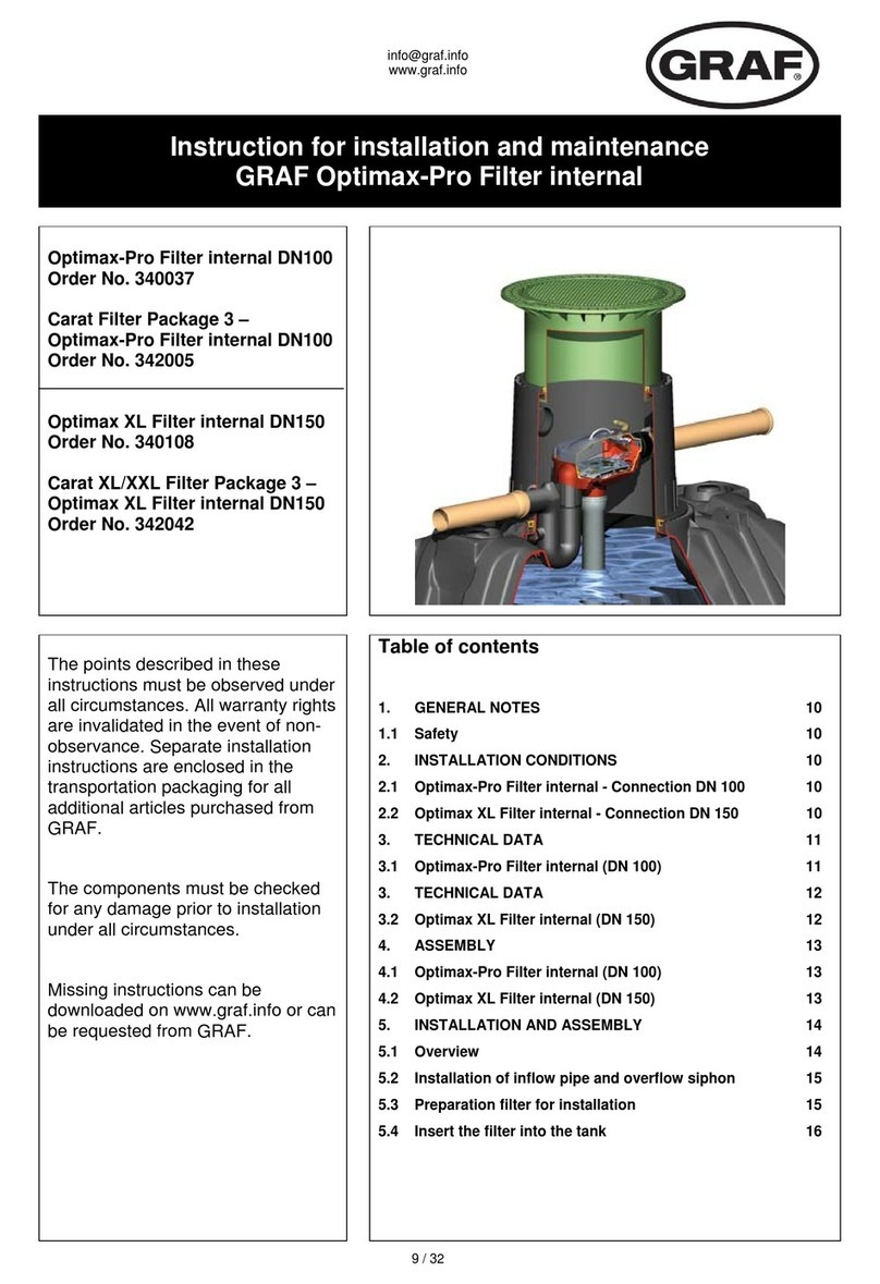
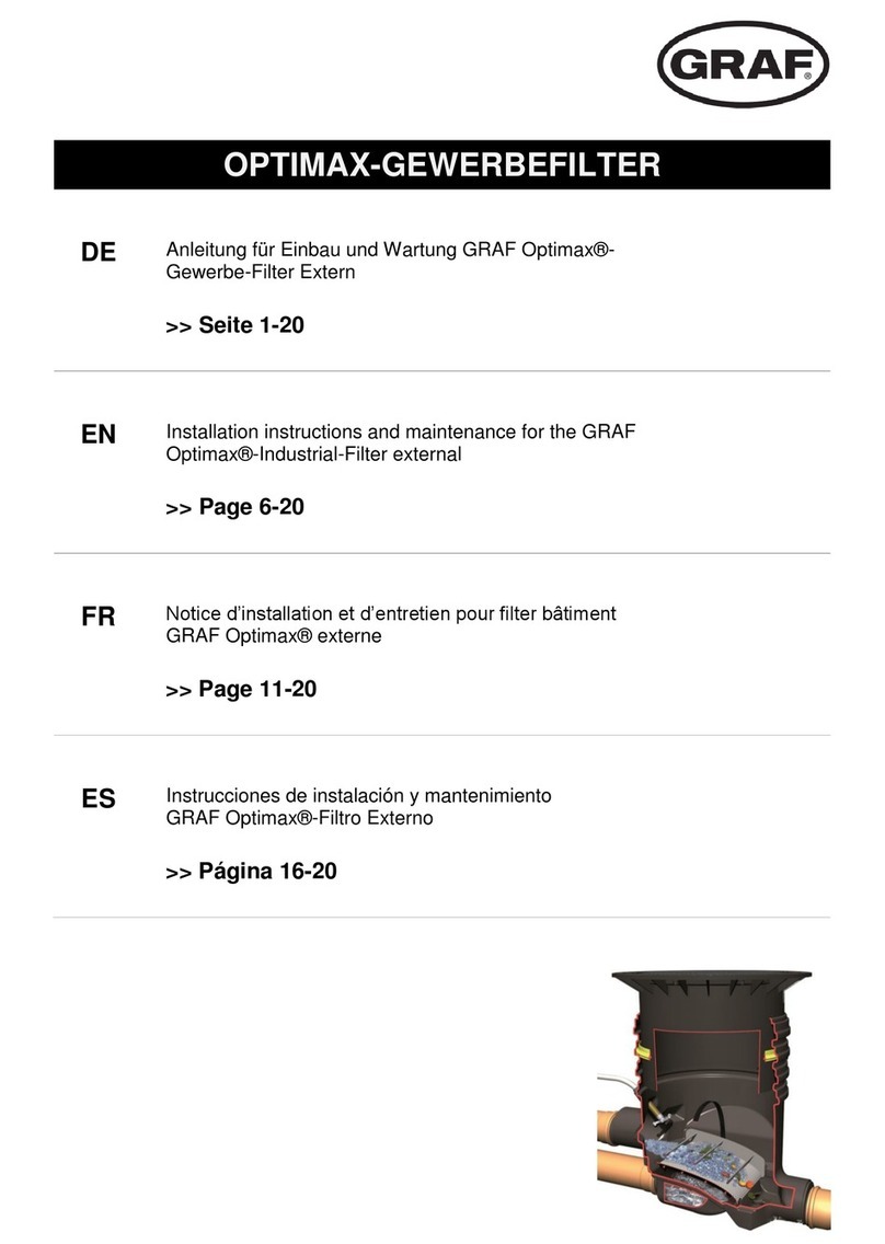
Graf MINIMAX 340060 User manual

www.graf.info
1 / 32
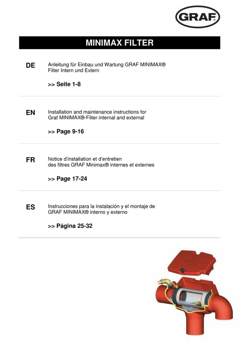
Anleitung für Einbau und Wartung
GRAF MINIMAX®-Filter Intern und Extern
MINIMAX®-Filter Intern
Art Nr.: 340060
MINIMAX®-Filter Extern
begehbar
Art Nr.: 340061
MINIMAX®-Filter Extern
PKW-befahrbar
Art Nr.: 340062
GRAF Ausbaupaket MINIMAX
Art Nr. 342025
Die in dieser Anleitung
beschriebenen Punkte sind
unbedingt zu beachten. Bei
Nichtbeachtung erlischt jeg-
licher Garantieanspruch. Für
alle über GRAF bezogenen
Zusatzartikel erhalten Sie
separate in der Transport-
verpackung beiliegende
Einbauanleitungen.
Fehlende Anleitungen sind
umgehend bei uns anzufordern.
Eine Überprüfung der
Komponenten auf eventuelle
Beschädigungen hat unbedingt
vor der Installation zu erfolgen.
Fehlende Anleitungen können
Sie unter www.graf.info
downloaden oder bei GRAF
anfordern.
Inhaltsübersicht
1. ALLGEMEINE HINWEISE 2
1.1 Sicherheit 2
1.2 Kennzeichnungspflicht 2
2. EINBAUBEDINGUNGEN 2
2.1 MINIMAX®-Filter intern: 2
2.2 MINIMAX®-Filter extern begehbar: 2
2.3 MINIMAX®-Filter extern PKW-befahrbar: 2
3. TECHNISCHE DATEN MINIMAX®-FILTER INTERN 3
4. TECHNISCHE DATEN MINIMAX®-FILTER EXTERN 4
5. EINBAU UND MONTAGE 5
5.1 MINIMAX®-Filter intern 5
5.2 MINIMAX®-Filter extern 6
5.2.1 Baugrube 6
5.2.2 Anschlüsse legen 6
5.2.3 Einsetzen und Verfüllen 6
5.2.4 Teleskop montieren 6
5.2.5 Teleskop PKW befahrbar 7
6. INBETRIEBNAHME UND WARTUNG 7
6.1 Inbetriebnahme 7
6.2 Wartung 7
7. WIRKUNGSGRAD 8
8. MONTAGE REINIGUNGSEINHEIT 8
Deutsch 1
English 9Français 17Español 25

www.graf.info
2 / 32
1. Allgemeine Hinweise
1.1 Sicherheit
Bei sämtlichen Arbeiten sind die einschlägigen Unfallverhütungsvorschriften nach BGV C22 zu beachten.
Besonders bei Begehung der Behälter ist eine 2. Person zur Absicherung erforderlich.
Des Weiteren sind bei Einbau, Montage, Wartung, Reparatur usw. die in Frage kommenden Vorschriften
und Normen zu berücksichtigen. Hinweise hierzu finden Sie in den dazugehörigen Abschnitten dieser
Anleitung.
Bei sämtlichen Arbeiten an der Anlage bzw. Anlagenteilen ist immer die Gesamtanlage außer Betrieb zu
setzen und gegen unbefugtes Wiedereinschalten zu sichern.
Die Firma GRAF bietet ein umfangreiches Sortiment an Zubehörteilen, die alle aufeinander abgestimmt
sind und zu kompletten Systemen ausgebaut werden können. Die Verwendung anderer Zubehörteile
kann dazu führen, dass die Funktionsfähigkeit der Anlage beeinträchtigt und die Haftung für daraus
entstandene Schäden aufgehoben wird.
1.2 Kennzeichnungspflicht
Das Betriebswasser ist nicht zum Verzehr und zur Körperhygiene geeignet.
Alle Leitungen und Entnahmestellen von Brauchwasser sind mit den Worten „Kein Trinkwasser“
schriftlich oder bildlich zu kennzeichnen (DIN 1988 Teil 2, Abs. 3.3.2.) um auch nach Jahren eine
irrtümliche Verbindung mit dem Trinkwassernetz zu vermeiden. Auch bei korrekter Kennzeichnung kann
es noch zu Verwechslungen kommen, z.B. durch Kinder. Deshalb müssen alle Brauchwasser –
Zapfstellen mit Ventilen mit Kindersicherung installiert werden.
2. Einbaubedingungen
2.1 MINIMAX®-Filter intern:
Der MINIMAX®-Filter Intern ist geeignet für den Einbau in einen Vorschacht oder eine Zisterne
Der Höhenunterschied zwischen Zulauf und Ablauf beträgt 80 mm
Der Filter ist geeignet für Dachflächen bis 350 m².
Die Maschenweite der Siebpatrone beträgt 0,5 mm.
2.2 MINIMAX®-Filter extern begehbar:
Der MINIMAX®-Filter Extern ist geeignet für den Einbau ins Erdreich vor einer Zisterne.
Der MINIMAX®-Filter Extern begehbar darf nur im nicht befahrenen Grünbereich eingebaut
werden.
Der Höhenunterschied zwischen Zulauf und Ablauf beträgt 10 mm.
Stufenlose Einbautiefe von 485 mm - 955 mm.
Der Filter ist geeignet für Dachflächen bis 350 m².
Die Maschenweite der Siebpatrone beträgt 0,5 mm.
2.3 MINIMAX®-Filter extern PKW-befahrbar:
Der MINIMAX®-Filter Extern PKW-befahrbar kann mit der Abd. Kl. B 125 unter PKW-befahrbaren
Flächen eingebaut werden.

www.graf.info
3 / 32
110
110
370
110
195
545
80
720
260
Zulauf Ablauf
Tank
Siphon
Fließrichtung
3. Technische Daten MINIMAX®-Filter intern

www.graf.info
4 / 32
550
400
510
110
555
85 85
400
145
155
100
Zulauf Ablauf
Tank
min: 485 / max: 955
Fließrichtung
Tank Tank
Zulauf
4. Technische Daten MINIMAX®-Filter extern

www.graf.info
5 / 32
Rohrlänge inkl. Muffe:
1500 Liter = 450 mm
3000 Liter = 480 mm
5000 Liter = 660 mm
(alle Maße +/- 3% Toleranz)
beruhigter Zulauftopf
MINIMAX-Filter intern
Schraube
Überlaufsiphon
(DN100)
Zulauf DN100
(250mm)
MINIMAX-Filter
Intern
Schnellmontage-
Manschette
beruhigter Zulauftopf
5. Einbau und Montage
5.1 MINIMAX®-Filter intern
Der MINIMAX®-Filter Intern wird wie in
nebenstehender Abbildung gezeigt vorbereitet.
Das Filtergehäuse wird über ein bauseits zu
stellendes KG-Rohr mit dem beruhigten Zulauf-
topf (im Ausbaupaket MINIMAX enthalten)
verbunden. Die Muffenverbindungen sollten mit
handelsüblichen Spaxschrauben gesichert
werden.
Anschließend werden am Zulauf und Überlauf des
Erdtanks Platin ein 250 mm langes Zulaufrohr
sowie der Überlaufsiphon, wie in der neben-
stehenden Abbildung gezeigt, bis zum Anschlag
eingeschoben.
Jetzt den vorbereiteten MINIMAX®-Filter Intern in
den Tank einsetzen, der Bogen am Überlauf des
Filters wird dabei in den Überlaufsiphon gesteckt.
Das Zulaufrohr wird so ausgerichtet, dass es
bündig mit dem Filterzulauf abschließt und
anschließend mit der Schnellmontage-Manschette
fixiert.
Auf keinen Fall dürfen im Überlauf
Kleintiersperren installiert werden, da es durch
Schmutz der zum Kanal geleitet wird zu
Rohrverstopfungen kommen kann.
Rohrlänge inkl. Muffe:
1500 L = 470 mm
3000 L = 500 mm
5000 L = 680 mm
7500 L = 1050 mm
(alle Maße +/-3% Toleranz)

www.graf.info
6 / 32
5. Einbau und Montage
5.2 MINIMAX®-Filter extern
5.2.1 Baugrube
Damit ausreichend Arbeitsraum vorhanden ist und der Filter gleichmäßig verdichtet werden kann, muss
die Grundfläche der Baugrube die Filtermaße auf jeder Seite um ca. 300 mm überragen.
Die Böschung ist nach DIN 4124 anzulegen. Der Baugrund muss waagerecht und eben sein.
Die Tiefe der Grube ist so zu bemessen, dass die max. Einbautiefe (955 mm ab Oberkante Filter) nicht
überschritten wird. Für die ganzjährige Nutzung der Anlage ist eine Installation der wasserführenden
Anlagenteile im frostfreien Bereich notwendig, genaue Angaben hierzu erhalten Sie bei der zuständigen
Behörde.
5.2.2 Anschlüsse legen
Sämtliche Zu- bzw. Überlaufleitungen sind mit einem
Gefälle von mind. 1 % zu verlegen (nachträgliche
Setzungen sind dabei zu berücksichtigen). Der
Anschluss erfolgt an den angeformten Stutzen am
Filtergehäuse. Um die Fließgeschwindigkeit des
Wassers zu reduzieren sollte das Zulaufrohr vor dem
Filter ca. 2 m waagerecht verlegt werden.
Die DIN 1986 ist unbedingt zu beachten, d.h.
Ø Zulauf < Ø Ablauf.
Wird nur einer der beiden Tankzulaufstutzen
angeschlossen, sollte der Filter ca. 1 % in die
Richtung der Leitung geneigt werden, damit im
Gegenüberliegenden Stutzen kein Wasser stehen
bleiben kann.
5.2.3 Einsetzen und Verfüllen
Der Filter ist stoßfrei in die vorbereitete Baugrube einzubringen. Vor dem Anfüllen mit Rundkornkies ist
die Lage des Filters zu prüfen, anschließend wird in Schichten von ca. 30 cm die Umhüllung angefüllt.
Die einzelnen Lagen müssen gut verdichtet werden (Handstampfer). Beim Verdichten ist eine
Beschädigung des Filters zu vermeiden. Es dürfen auf keinen Fall mechanische Verdichtungsmaschinen
eingesetzt werden. Die Umhüllung muss mind. 30 cm breit sein.
5.2.4 Teleskop montieren
Das Teleskop wird von oben in das Filtergehäuse
eingeschoben. Es ist unbedingt darauf zu achten,
dass die Zuleitung im endgültig eingebauten
Zustand nicht vom Teleskop ganz oder teilweise
verschlossen wird. Vor dem Einschieben wird die
Profildichtung in die Dichtnut des Gehäuses
eingesetzt. Das Teleskop, sowie die Dichtung
müssen mit der mitgelieferten Schmierseife (keine
Schmierstoffe auf Mineralölbasis verwenden)
großzügig eingerieben werden.
Achtung: Trocknet die Schmierseife an lässt sich das Teleskop nur noch sehr schwer bewegen und es
besteht die Gefahr, dass die Dichtung aus der Dichtnut rutscht. Vor dem Verfüllen muss die Dichtung auf
ihren korrekten Sitz überprüft werden. Das Teleskop muss ausreichend unterfüttert werden, so dass sich
Kräfte auf keinen Fall auf das Gehäuse übertragen können.
Der Filter ist auf keinen Fall befahrbar und darf nur im nicht befahrenen Grünbereich installiert werden.
www.graf.info
7 / 32
Zulaufseite Überlaufseite
Dichtring
Fließrichtung
Dichtring
Pfeilmarkierung
unter der
Dichtung
Lippe
5. Einbau und Montage
5.2.5 Teleskop PKW befahrbar
Um die PKW - Befahrbarkeit zu gewährleisten muss unter dem Teleskopkragen mit Magerbeton
unterfüttert werden. Die anzufüllende Betonschicht muss mind. 20 cm breit und ca. 30 cm dick sein.
Achtung: Unbedingt die Stahl – Gussabdeckung verwenden. Verkehrslasten von LKW sind nicht
zulässig. Das Teleskop muss ausreichend unterfüttert werden, so dass sich Kräfte auf keinen Fall auf das
Gehäuse übertragen können.
6. Inbetriebnahme und Wartung
6.1 Inbetriebnahme
Vor Inbetriebnahme ist die Siebfläche gründlich mit einem
fettlösenden Putzmittel zu reinigen. Alternativ ist auch eine
Reinigung in der Geschirrspülmaschine (40° - max. 60°)
möglich. Schmutz, der durch die Montage ins
Filtergehäuse gelangt ist, ist zu entfernen.
Der Siebeinsatz funktioniert aufgrund der Siebstruktur nur
in einer bestimmten Fließrichtung, diese ist durch eine
Pfeilmarkierung im Metallring auf der Zulaufseite kenntlich
gemacht. Beim Einsetzen der Filterpatrone darauf achten,
dass die Verbindungsnaht der Siebfläche oben liegt.
6.2 Wartung
Die gesamte Anlage ist mind. alle drei Monate auf
Dichtheit, Sauberkeit und Standsicherheit zu überprüfen.
Um eine gleichmäßig hohe Wasserausbeute zu
gewährleisten ist die Siebfläche in regelmäßigen
Abständen auf Verschmutzungen zu prüfen und ggf. zu
reinigen. Bei Wartungen am integrierten Filter ist
zusätzlich der Überlaufsiphon regelmäßig zu kontrollieren
und zu reinigen.

www.graf.info
8 / 32
7. Wirkungsgrad
Bei einem normalen Regen von 150 l/s je ha fällt auf eine Dachfläche von 150 m² ca. 2,25 l/s, das
entspricht 135 l/min.
Der MINIMAX®-Filter hat bei diesem Volumenstrom einen Wirkungsgrad von 99 %, d. h. in der Praxis,
dass ein Erdtank mit 4000 L Volumen in ca. 30 Minuten komplett gefüllt ist.
8. Montage Reinigungseinheit
Die Messing Düse ¾“ wird in die vorgesehene Öffnung auf der Zulaufseite des Filtergehäuses eingesetzt
und von außen mit dem Messing-Bogen fixiert. Anschließend die Messing-Schlauchtülle mit
Überwurfmutter aufschrauben und mit dem Schlauch (bauseits) verbinden. Der Schlauch wird durch das
Leerrohr zur Pumpe geführt und auf der Druckseite nach einem Absperrhahn mit der Druckleitung
verbunden.
Otto Graf GmbH – Carl-Zeiss-Str. 2-6 – D-79331 Teningen – Tel.: 0049/(0)7641/589-0 – Fax: 0049/(0)7641/589-50
GRAF SARL – 45, Route d´Ernolsheim – F-67120 Dachstein Gare – Tel.: 0033/388497310 – Fax: 0033/388493280
GRAF Iberica – C/Marquès Caldes de Montbui, 114 baixos – ES-17003 Girona – Tel.: +34/972 913 767 – Fax: +34/972 913 766
GRAF Ltd – Maidstone, Kent – UK-ME16 8Ry – Phone: +44 (0) 16 22 68 65 50 05-2011
Wirkungsgrad [%] / Volumenstrom [l/min]
86
88
90
92
94
96
98
100
102
1234
Volumenstrom [100 l/min]
Wirkungsgrad [%]

www.graf.info
9 / 32
Installation and maintenance instructions for
GRAF MINIMAX®-Filter internal and external
MINIMAX®-Filter Internal
Order No.: 340060
MINIMAX®-Filter External
pedestrian
Order No.: 340061
MINIMAX®-Filter External
for areas traversed by light
traffic
Order No.: 340062
GRAF Filter package
MINIMAX
Order No. 342025
The points described in these
instructions must be observed
under all circumstances. All
warranty rights are invalidated
in the event of non-observance.
Separate installation
instructions are enclosed in the
transportation packaging for all
additional articles purchased
from GRAF.
Missing instructions must be
requested from us immediately.
The components must be
checked for any damage prior to
installation under all
circumstances.
Missing instructions can be
downloaded on www.graf.info or
can be requested from GRAF.
Table of contents
1. GENERAL NOTES 10
1.1 Security 10
1.2 Identification obligation 10
2. INSTALLATION CONDITIONS 10
2.1 MINIMAX®-Filter internal: 10
2.2 MINIMAX®-Filter external pedestrian: 10
2.3 MINIMAX®-Filter extern PKW-befahrbar: 10
3. TECHNICAL DATA MINIMAX®-FILTER INTERNAL 11
4. TECHNICAL DATA MINIMAX®-FILTER EXTERNAL 12
5. INSTALLATION AND ASSEMBLY 13
5.1 MINIMAX®-Filter internal 13
5.2 MINIMAX®-Filter external 14
6. COMMISSIONING AND SERVICE 15
6.1 Commissioning 15
6.2 Service 15
7. EFFICIENCY / PERFORMANCE 16
8. MOUNTING OF CLEANING UNIT 16
Deutsch 1
English 9
Français 17Español 25

www.graf.info
10 / 32
1. General notes
1.1 Security
The relevant accident prevention regulations according to BGV C22 must be observed during all work.
Particularly when walking on the tanks, a 2nd person is required to secure the tank.
The relevant regulations and standards must additionally be taken into consideration during installation,
assembly, servicing, repair, etc. Relevant notes can be found in the corresponding sections of these
instructions.
During all work on the system or parts of the system, the entire system must always be rendered
inoperable and secured to prevent unauthorised reactivation.
GRAF offers an extensive range of accessories, all of which are designed to match each other and which
can be extended to form complete systems. The use of other accessories may lead to impediments to the
system's functional capability, therefore invalidating liability for resulting damage.
1.2 Identification obligation
The water in these systems is not suitable for consumption or personal hygiene.
All pipe work and outlets of the water systems are to be labelled with the words “Not drinking water”
either in words or graphically (German norm DIN 1988 Part 2, paragraph 3.3.2.) so that after years of use,
an accidental connection to the drinking water system is prevented. Even when correctly labelled it may
possibly be mistaken, for example by children. For this reason, all the outlets of the systems process
water must be fitted with child safe valves.
2. Installation conditions
2.1 MINIMAX®-Filter internal:
The MINIMAX®-Filter Internal is suitable for installation in a pilot shaft or in a cistern
The difference in height between the supply pipe and outlet is 80 mm
The filter is suitable for roof areas up to 350 m².
The mesh aperture in the filter cartridge is 0.5 mm.
2.2 MINIMAX®-Filter external pedestrian:
The MINIMAX-Filter External is suitable for installation underground prior to a cistern inlet.
The MINIMAX-Filter External may only be installed in areas that are not traversed by traffic.
The difference in height between the supply pipe and outlet is 10 mm
Stepless installation depth from 570 mm to 1050 mm.
The filter is suitable for roof areas up to 350 m².
The mesh aperture in the filter cartridge is 0.5 mm.
2.3 MINIMAX®-Filter external for areas traversed by light traffic:
The MINIMAX®-Filter External for areas traversed by light traffic could be installed in areas
traversed by light traffic by using the cast iron cover class B 125.

www.graf.info
11 / 32
110
110
370
110
195
545
80
720
260
Zulauf Ablauf
Tank
Siphon
Fließrichtung
3. Technical data MINIMAX®-Filter Internal
Designed structure
Outflow
Inflow

www.graf.info
12 / 32
550
400
510
110
555
85 85
400
145
155
100
Zulauf Ablauf
Tank
min: 485 / max: 955
Fließrichtung
Tank Tank
Zulauf
4. Technical data MINIMAX®-Filter External
Inflow
Outflow
Designed structure
Inflow

www.graf.info
13 / 32
Rohrlänge inkl. Muffe:
1500 Liter = 450 mm
3000 Liter = 480 mm
5000 Liter = 660 mm
(alle Maße +/- 3% Toleranz)
beruhigter Zulauftopf
MINIMAX-Filter intern
Schraube
Überlaufsiphon
(DN100)
Zulauf DN100
(250mm)
MINIMAX-Filter
Intern
Schnellmontage-
Manschette
beruhigter Zulauftopf
5. Installation and assembly
5.1 MINIMAX®-Filter internal
The MINIMAX®-Filter Internal is prepared as
shown in the adjacent depiction. The filter housing
is connected via the on site installed canalisation
pipe to the stabilising inlet well (included in the
MINIMAX add on packet). The couplings should
be secured with commercial self tapping screws.
Following this a 250 mm long inlet pipe and an
overflow siphon are pushed in to the Platin
underground tank until the end stop position as
shown in the adjacent depiction.
Now the prepared MINIMAX®-Filter internal is
installed in the tank, the elbow of the overflow
from the filter is also connected now to the siphon.
The inlet pipe is so to position that it is flush with
the filter inlet and then finally fixed in place with
the quick assembly collar.
Under no circumstance may a mesh barrier to
prevent small animals entering the tube be
installed as this will eventually lead to a blockage
from debris in the pipe.
Pipe length with bush:
1500 L = 470 mm
3000 L = 500 mm
5000 L = 680 mm
7500 L = 1050 mm
MINIMAX-Filter internal
settled inlet basked
Screw
Inflow DN 100
L: 250 mm
Overflow-
siphon DN 100
settled inlet basked
Quick assembly
sleeve
MINIMAX-
Filter internal
(all dimensions +/- 3% Tolerance)

www.graf.info
14 / 32
5. Installation and assembly
5.2 MINIMAX®-Filter external
5.2.1 Excavation
So that sufficient working room is available and the filter can be evenly embedded, the surface area of the
excavation should exceed the filter dimensions on all sides by approximately 300 mm.
The excavation slope is according to DIN 4124. The installations excavation must be level and smooth.
The depth of the excavation must be measured so that the maximum installation depth (970 mm from the
top surface of the filter) is not exceeded. For an all year round utilisation of the system it is necessary that
the water transporting parts of the installation and equipment are installed in a frost free environment,
precise data regarding this should be requested from the appropriate administrative authority.
5.2.2 Laying connections
All supply and run off pipes must have a gradient of at
least 1% (subsequent settling of the fill materials should
be taken into account). The connection is made to the
moulded pipe connections on the filter housing. To
reduce the flow rate of the water the inlet pipe should be
laid level for approximately the last 2 m before joining
the filter.
The German DIN 1986 must be complied with, this
means Ø inlet and < Ø outlet.
If only one of the two tank supply pipe connections be
connected then the filter should be inclined
approximately 1% towards the pipe so that no water may
remain standing at the opposite connection.
5.2.3 Placing and filling
The filter is to be installed without damage in the
prepared excavation. Before back-filling with smooth sand the position of the filter should be checked and
then embedded in layers of not more than 30 cm.
Each layer must be well compacted with a hand held tamper. Care must be taken during the embedding
to ensure the filter is not damaged. Under no circumstances should powered compacting machines be
used. The surrounding back fill must be at least 30 cm wide.
5.2.4 Telescope installation
The telescope is pressed into the filter housing
from above. It is important to pay attention that the
inlet pipe is not obstructed in any way by the
telescope when installed. Before pushing in the
telescope the profiled sealing ring is placed in the
housings recess. The telescope and the sealing
ring must be thoroughly coated with the lubricating
soap included in the delivery (use no lubrication
that is mineral oil based). Attention: If the
lubricating soap
becomes dry and the telescope becomes difficult
to move then there is the danger that the sealing ring will be forced out of its recess. Before filling the
sealing ring must be checked once again that it is seated correctly in position. The telescope must be
sufficiently embedded and supported that no forces are transferred to the housing.
The filter may under no circumstances be traversed by traffic and is only to be installed in green areas.

www.graf.info
15 / 32
Inflow side Overflow side
Sealingring
Designedstructure
Sealingring
Arrowdesignation
under the seal
Lip
5. Installation and assembly
5.2.5 Telescope suitable for light traffic
To ensure the function in areas traversed by light traffic, the telescope must be embedded around the
collar with lean mixed concrete.
The concrete encasement must be uninterrupted, 20 cm wide and approximately 30 cm deep.
Attention: It is important to use the cast steel cover. Transport vehicle weight of heavy goods vehicles
and machinery is not permitted. The telescope must be sufficiently embedded and supported that no
forces are transferred to the housing.
6. Commissioning and Service
6.1 Commissioning
Before putting the system into use the filter sieve
surface is to be thoroughly cleaned with asolvent based
cleaning fluid. Alternatively the filter sieve may be
cleaned in a dish washer (40° - max. 60°). Any dirt that
gets into the filter housing during the assembly must be
thoroughly removed.
The filter sieve functions only in one flow direction due
to the designed structure, the direction is marked on the
metal ring with an arrow on the inlet side. When
installing the filter cartridge pay attention that the joint
seam of the sieve surface is positioned upward.
6.2 Service
The complete system is to be inspected at least every 3
months for leakage, cleanliness stability. To ensure the
expected water yield is delivered, it is important to
inspect and to clean the filter sieve at regular intervals.
When carrying out a regular service of the integrated
filter it is also required that the overflow siphon is
checked and cleaned.

www.graf.info
16 / 32
7. Efficiency / Performance
In the case of normal rainfall of 150 l/s, the amount of water to be harvested from a roof area of 150 m² is
approximately 2.25 l/s, that is equal to 135 l/min.
The MINIMAX-Filter has with this flow volume an efficiency factor of 99%, this means in real terms that a
tank with a volume of 4000 l will be filled in approximately 30 minuets.
8. Mounting of cleaning unit
The brass jet ¾“ is to be inserted in the provided aperture at the inlet side of the filter housing and fixed
with the brass bend from the outside. Afterwards the brass hose nozzle is to be screwed on with a union
nut and connected with the hose (provided by customer). The hose is conducted through the empty
conduit to the pump and linked with the pressure line on the pressure side after a cut-off cock.
Otto Graf GmbH – Carl-Zeiss-Str. 2-6 – D-79331 Teningen – Tel.: 0049/(0)7641/589-0 – Fax: 0049/(0)7641/589-50
GRAF SARL – 45, Route d´Ernolsheim – F-67120 Dachstein Gare – Tel.: 0033/388497310 – Fax: 0033/388493280
GRAF Iberica – C/Marquès Caldes de Montbui, 114 baixos – ES-17003 Girona – Tel.: +34/972 913 767 – Fax: +34/972 913 766
GRAF Ltd – Maidstone, Kent – UK-ME16 8Ry – Phone: +44 (0) 16 22 68 65 50 05-2011
brass bend ¾“
brass hose nozzle
brass jet ¾“

www.graf.info
17 / 32
Notice d’installation et d’entretien
des filtres GRAF Minimax®internes et externes
MINIMAX®- Filtre interne
Réf. : 340060
MINIMAX®-Filtre externe
Passage piétons
Réf. : 340061
MINIMAX®-Filtre externe
Passage véhicules ≤2T
Réf : 340062
GRAF Pack Filtre MINIMAX
Réf.: 342025
Afin de garantir le bon
fonctionnement et la longévité
de votre installation, il est
important de respecter
scrupuleusement les
instructions de mise en place du
fabricant. Tout manquement à
ces règles annulera
systématiquement la garantie.
Toute notice manquante doit
nous être réclamée sans délai.
Avant d’installer les
components, il est important de
vérifier que celle-ci n’a pas été
endommagée.
Les notices manquantes
peuvent être téléchargées sur
www.graf.info ou être
demandées auprès de la société
GRAF.
Sommaire
1. GÉNÉRALITÉS 18
1.1 Sécurité 18
1.2 Marquage 18
2. INSTALLATION 18
2.1 Filtre Minimax interne: 18
2.2 Filtre Minimax externe passage piétons: 18
2.3 Filtre Minimax Externe passage véhicules (≤2T): 19
3. SPECIFICATIONS TECHNIQUES: FILTRE MINIMAX
INTERNE 19
4. SPECIFICATION TECHNIQUES: FILTRE MINIMAX
EXTERNE 20
5. INSTALLATION ET MONTAGE 21
5.1 Filtre Minimax interne 21
5.2 Filtre Minimax externe 22
5.2.1 Excavation 22
5.2.2 Raccordement 22
5.2.3 Mise en place et remplissage 22
5.2.4 Montage de la rehausse telescopique passage piétons 22
5.2.5 Rehausse télescopique passage véhicules (≤2T) 23
6. MISE EN SERVICE ET ENTRETIEN 23
6.1 Mise en service 23
6.2 Entretien 23
7. RENDEMENT DU FILTRE 24
8. MONTAGE DE LA BUSE DE NETTOYAGE 24
Deutsch 1English 9
Français 17
Español 25

www.graf.info
18 / 32
1. Généralités
1.1 Sécurité
Les règles de sécurité doivent impérativement être respectées lors de l’installation de la cuve. Durant
l’inspection de la cuve, une 2ème personne doit être présente.
Les instructions d’installation, de montage, d’entretien et de réparation indiquées ci-après doivent être
scrupuleusement respectées.
Durant toute intervention sur la cuve ou les accessoires, l’installation complète doit être mise hors
service.
Pour des raisons de sécurité, le couvercle de la cuve doit impérativement être verrouillé.
Seuls les couvercles et rehausses GRAF doivent être utilisés.
Le filtrage ne rend pas l’eau de pluie potable. Vous devez impérativement apposer à proximité de
chaque sortie d’eau de pluie la mention « Eau non potable ».
En aucun cas l’eau de pluie ne doit circuler dans les tuyaux d’eau potable du réseau. Une seule
tuyauterie doit alimenter les toilettes et la machine à laver le linge. Celle-ci doit être branchée à
partir d’une station de pilotage réglementaire (de type station de pilotage GRAF répondant aux
normes européennes en vigueur) prévoyant en sécurité une disconnexion entre les deux réseaux
et un trop-plein.
La société GRAF vous propose une large gamme d’accessoires d’une grande compatibilité. L’utilisation
d’autres accessoires peut contribuer à un mauvais fonctionnement de l’installation. Les dommages subis
dans ce cas ne sont pas garantis.
1.2 Marquage
L’eau de pluie simplement filtrée (c’est-à-dire non traitée) ne doit en aucun cas être utilisée pour
une consommation courante ou l’hygiène corporelle.
Afin d’éviter toute confusion, toutes les sorties d’eau de pluie doivent être signalées par la mention écrite
ou en image « Eau non potable ». Les tuyauteries doivent être marqué d’un adhésif de couleur pour être
repérées facilement. Toutes les sorties doivent être équipées de vannes « sécurité enfant ».
2. Installation
2.1 Filtre Minimax interne:
Le filtre Minimax interne est adapté pour la mise en place dans une cuve ou un regard de visite.
L’entre-axe entre l’arrivée des eaux de pluie et la sortie trop-plein est de 80 mm
Convient aux surfaces de toiture ≤350 m².
Epaisseur de la maille filtrante: 0,5 mm.
2.2 Filtre Minimax externe passage piétons:
Le filtre Minimax externe doit être enterré avant la cuve de récupération d’eau de pluie.
Il est interdit de circuler avec un véhicule sur le Filtre Minimax Externe – passage piétons –
rehausse télescopique couleur vert, couvercle PE couleur vert.
Faible entre-axe: 10 mm.
Profondeur d’installation ajustable de 485 mm à 955 mm.
Convient aux surfaces de toiture ≤350 m².
Epaisseur de la maille filtrante: 0,5 mm.

www.graf.info
19 / 32
110
110
370
110
195
545
80
720
260
Zulauf Ablauf
Tank
Siphon
Fließrichtung
2. Installation
2.3 Filtre Minimax Externe passage véhicules (≤2T):
Possibilité de circuler sur la rehausse télescopique couleur noir avec couvercle en fonte pour les
véhicules de la catégorie B d’un poids inférieur ou égal à 2 tonnes.
En aucun cas ce filtre ne doit être installé dans un lieu de passage de camions.
La hauteur de recouvrement au-dessus du tuyau PVC d’arrivée d’eau de pluie dans le filtre doit
être au minimum de 450 mm.
Profondeur d’installation ajustable de 485 mm à 955 mm.
Convient aux surfaces de toiture 350 m².
Epaisseur de la maille filtrante : 0,5 mm.
3. Spécifications techniques: filtre Minimax interne
Sens de l’écoulement
Sortie
Entrée
Cuve

www.graf.info
20 / 32
550
400
510
110
555
85 85
400
145
155
100
Zulauf Ablauf
Tank
min: 485 / max: 955
Fließrichtung
Tank Tank
Zulauf
4. Spécification techniques: Filtre Minimax externe
Entrée Entrée
Sortie
Entrée Cuve Cuve Cuve
Sens de l’écoulement
This manual suits for next models
3
Table of contents
Languages:
Other Graf Water Filtration System manuals

Graf
Graf EcoPure 150 Instruction Manual

Graf
Graf MINIMAX Series User manual

Graf
Graf Optimax-Pro User manual

Graf
Graf MINIMAX-PRO Operating and maintenance manual

Graf
Graf Optimax-Pro Operating and maintenance manual

Graf
Graf EcoPure 200 Instruction Manual

Graf
Graf MINIMAX-PRO Platin Package 3 Operating and maintenance manual

Graf
Graf Optimax-XXL DN300 User manual

Graf
Graf Garden Comfort Platin 1500 L User manual

Graf
Graf one2clean+ XXL User manual