CAUTION
Prohibit the terminal of the
Ni-Cd battery connecter to
short circuit.
Short circuit may cause burn,
fire etc.
Prohibit impact strongly
the Ni-Cd battery such as
drop down.
If the battery is damage for
shorting or overheat abnormally,
and cause electrolyte leakage, it
may result in burn or corrosion
of chemical matter.
Prohibited
Prohibited
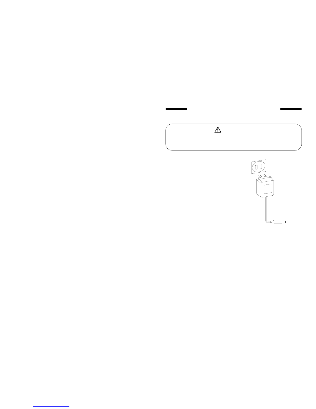
WARNING
Mandatory
STORAGE OF Ni Cd BATTERY-
Keep the battery, equipment
away from babies and
children.
They may injure for equipment
operating or licking battery.
Do not dispose the battery in a
fire, or heating them, and
prohibit disassembly or refit.
That may result in explode,
overheating, electrolyte
leakage, burn, injury, blindness,
etc.
Store the Ni-Cd battery in
discharging mode if you will
not fly the mini helicopter, and
recharge the battery before
preparing for flying.
If you repeat to charge battery
for a short time, in other words,
the battery has no charge fully,
for the sake of the battery has
memory function, then the
battery cannot charge filled, and
the time of flying will decrease,
may cause a crash.
Prohibited Mandatory
CAUTION
If not remove, the electrolyte
leakage of the batteries will
affect them performance and
Remove the batteries from
transmitter or helicopter if
you will not use them for a
long time.
Do not expose the battery to
direct sunlight, extreme
temperature (degrees Celsius
over 40 or under -10), high
humidity, full of dust, nearby
from heating appliances etc.
Those locations should be the
reason of bend or damage.
5
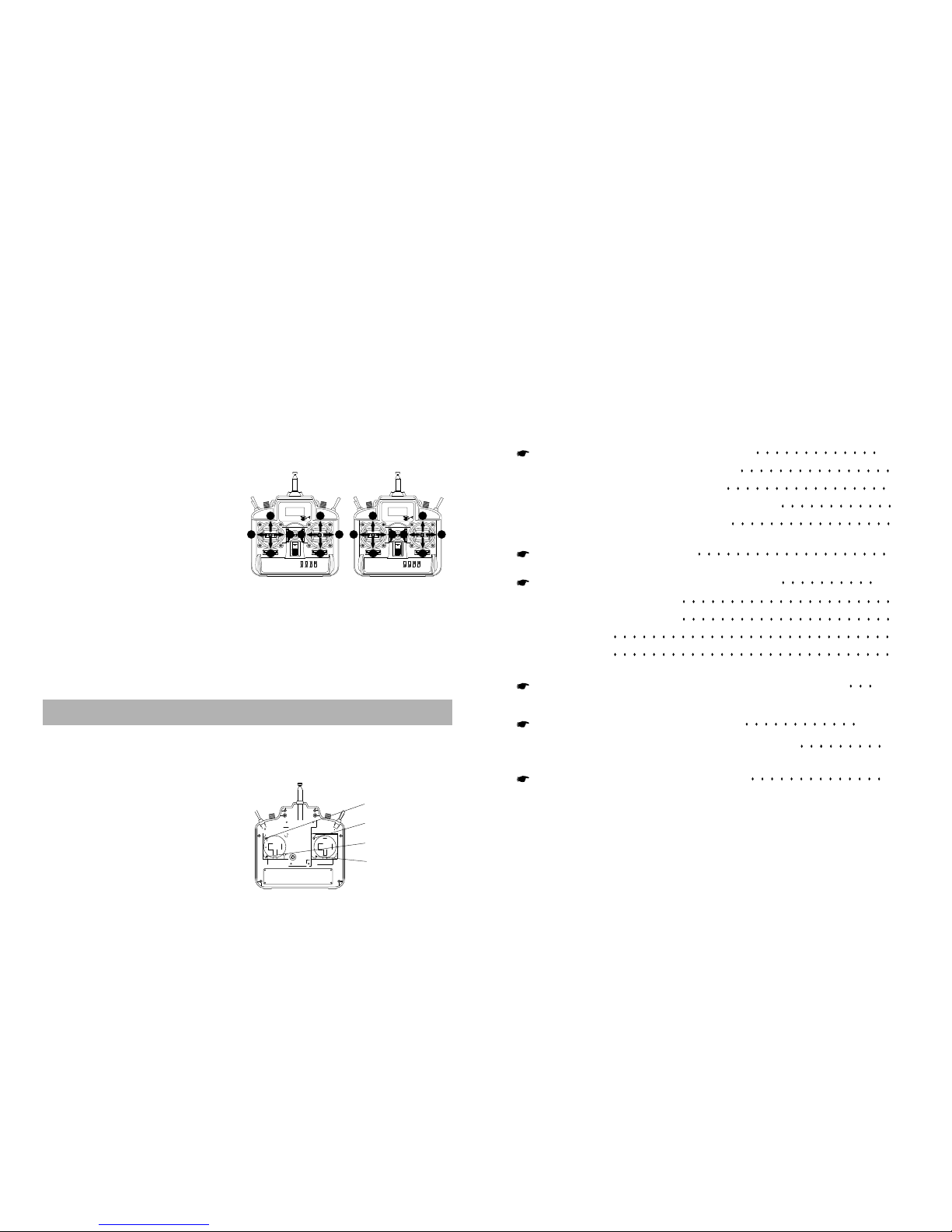
NAME AND HANDLING OF
EACH PART
TRANSMITTER FRONT( )
CONTENTS IN THE BOX
Please check following parts in the gift box.
The R/C transmitter
The H.F.M
The receiver
The servo
The instruction manual
1 piece
1 piece on the transmitter
1 pieces
4 pieces
1 piece
()
6
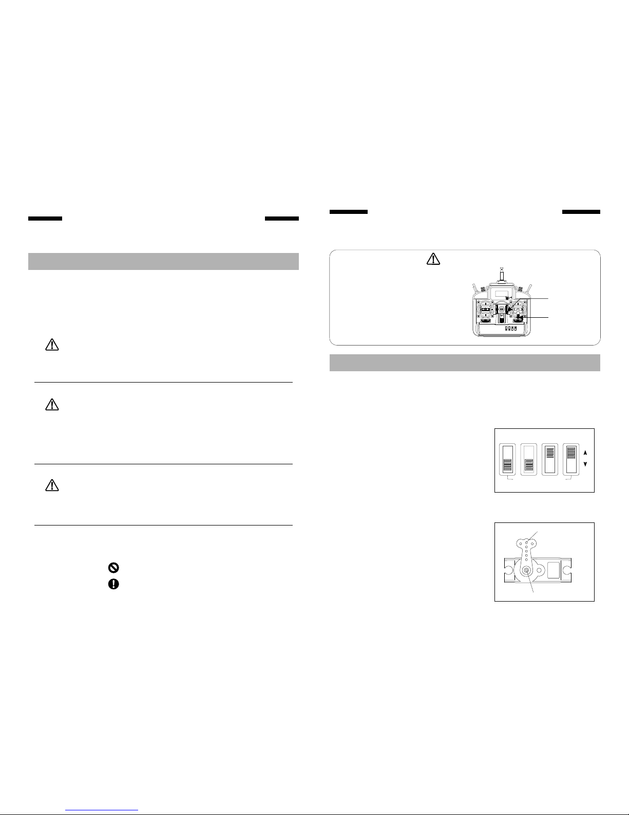
ON
LCD VOLTAGE INDICATOR
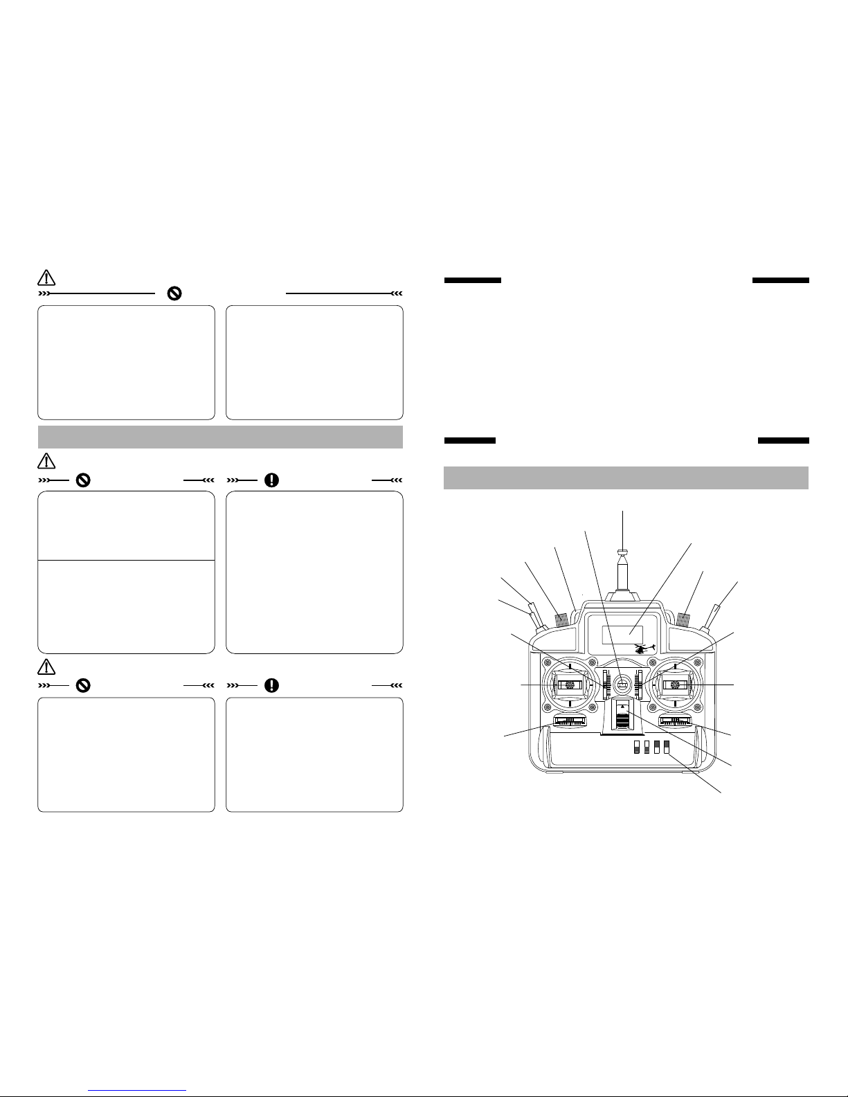
Carrying bar
Antenna
IDLE TRIN
LCD Voltage Indicator
Hook
Power switch
Rudder trim lever Aileron trim lever
Elevator trim lever
Mode 1
Throttle trim lever
Mode 2
()
()
Elevator Mode 1
Throttle Mode 2
rudder stick
()
()
/
Servo reversing switches
Throttle trim lever
Mode 1
Elevator trim lever
Mode 2
()
()
Throttle Mode 1
Elevator Mode 2
Aileron stick
()
()
/
HOV PIT.PIT TRIM.
GYRO SW.