manuals.online logo
Brands
  1. Home
  2. •
  3. Brands
  4. •
  5. FUTABA
  6. •
  7. Remote Control
  8. •
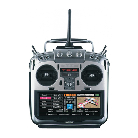
  9. FUTABA T16IZ Manual

FUTABA T16IZ Manual

Other manuals for T16IZ

8

This manual suits for next models

2

Other FUTABA Remote Control manuals

FUTABA FP-5FG User manual

FUTABA

FUTABA FP-5FG User manual

FUTABA T4PM User manual

FUTABA

FUTABA T4PM User manual

FUTABA 3PKS User manual

FUTABA

FUTABA 3PKS User manual

FUTABA 3PM-X 2.4GHZ User manual

FUTABA

FUTABA 3PM-X 2.4GHZ User manual

FUTABA PCM1024H User manual

FUTABA

FUTABA PCM1024H User manual

FUTABA T32MZ User manual

FUTABA

FUTABA T32MZ User manual

FUTABA 3PM-FS User manual

FUTABA

FUTABA 3PM-FS User manual

FUTABA 4VF-FM User manual

FUTABA

FUTABA 4VF-FM User manual

FUTABA 3PM User manual

FUTABA

FUTABA 3PM User manual

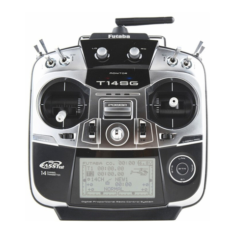
FUTABA 14SG User manual

FUTABA

FUTABA 14SG User manual

FUTABA 7CAP User manual

FUTABA

FUTABA 7CAP User manual

FUTABA 4PL-2.4GHZ User manual

FUTABA

FUTABA 4PL-2.4GHZ User manual

FUTABA 16SZ User manual

FUTABA

FUTABA 16SZ User manual

FUTABA 16IZS Installation instructions

FUTABA

FUTABA 16IZS Installation instructions

FUTABA Magnum Sport FP-S148 User manual

FUTABA

FUTABA Magnum Sport FP-S148 User manual

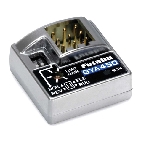
FUTABA GYA450 User manual

FUTABA

FUTABA GYA450 User manual

FUTABA FASSTest-2.4GHz T16SZ Series User manual
FUTABA

FUTABA FASSTest-2.4GHz T16SZ Series User manual

FUTABA FX40 User manual

FUTABA

FUTABA FX40 User manual

FUTABA T4GRS-24G User manual

FUTABA

FUTABA T4GRS-24G User manual

FUTABA R7314SB User manual

FUTABA

FUTABA R7314SB User manual

FUTABA T10PX Installation instructions

FUTABA

FUTABA T10PX Installation instructions

FUTABA MAGNUM SPORT FP-2P User manual

FUTABA

FUTABA MAGNUM SPORT FP-2P User manual

FUTABA 3PM Owner's manual

FUTABA

FUTABA 3PM Owner's manual

FUTABA R334SBS Technical manual

FUTABA

FUTABA R334SBS Technical manual

Popular Remote Control manuals by other brands

Bircher Reglomat RC Duo 2 user guide

Bircher Reglomat

Bircher Reglomat RC Duo 2 user guide

Emerson RCBT100 owner's manual

Emerson

Emerson RCBT100 owner's manual

BILDA Element-6 user manual

BILDA

BILDA Element-6 user manual

Absima CR7P manual

Absima

Absima CR7P manual

Mitsubishi Electric PAR-32MAAG Instruction book

Mitsubishi Electric

Mitsubishi Electric PAR-32MAAG Instruction book

RCA RCRTBL08BE1 quick start guide

RCA

RCA RCRTBL08BE1 quick start guide

US Electronics NOVARI user guide

US Electronics

US Electronics NOVARI user guide

Panasonic EUR7622KB0 Operation guide

Panasonic

Panasonic EUR7622KB0 Operation guide

Bang & Olufsen Beo4 user manual

Bang & Olufsen

Bang & Olufsen Beo4 user manual

Marantz RC101 user guide

Marantz

Marantz RC101 user guide

HR Matic HR MULTI 3 quick start guide

HR Matic

HR Matic HR MULTI 3 quick start guide

Anritsu MP1777A Operation manual

Anritsu

Anritsu MP1777A Operation manual

Niles WVC100 Installation & operating guide

Niles

Niles WVC100 Installation & operating guide

Bang & Olufsen BEO6 Getting started

Bang & Olufsen

Bang & Olufsen BEO6 Getting started

GE 94901 instruction manual

GE

GE 94901 instruction manual

Invacare G91S user manual

Invacare

Invacare G91S user manual

JR Racing XR2 user manual

JR Racing

JR Racing XR2 user manual

Philips SBCRU130/00U user manual

Philips

Philips SBCRU130/00U user manual

manuals.online logo
manuals.online logoBrands
  • About & Mission
  • Contact us
  • Privacy Policy
  • Terms and Conditions

Copyright 2025 Manuals.Online. All Rights Reserved.

1M23Z07717
Settingmanual
GYA553Ver.3
T16IZ/T16IZSUPER
2
ConnectionT16IZ/T16IZSUPERandGYA553
T16IZ/T16IZSUPER
S.I/F
CGY 接続コード(ジャイロに付属)
GYA553
ReceiverConnectionCable
(includedwithgyro)
ByinstallingthelatestsoftwareontheT16IZ/T16IZSUPER,youcan
settingtheairplanegyroGYA553ontheT16IZ/T16IZSUPER.
CAUTION
BesuretoconnectanddisconnecttheGYA553
andTransmitterconnectioncablewiththe
poweroff.
3
1.Select“Gyrosetting”onthelastpageof
AirplaneModelMenu
3.Homescreenisdisplayed
ToBasicmenu
◆ WhencopyingdatafromGyroAtoGyroB
ConnectthegyroAtothetransmitterandpress[Start].(EnterthedataofAintotransmitter)
ConnectGyroBtotransmitterandpress[GYSettingsTransfer].(PutdataonAintogyroB)
2.Select"Start"
Select"Start"
Thiswilldownloadthegyrodatato
thetransmitter.
*Atthistime,ifGyroisnotconnectedto
transmitterbywire,thisscreenappears.
Tap"Yes"todisplaytheGYA553datasaved
intransmitter.
1
3
2
SETTING
When"GYSettingsTransfer"is
selected,thegyrosettingdatasaved
intransmitteriswrittentothegyro.
IfyoupressStarthere,theBdatawillbedownloadtothe
transmitterandtheAdatawillbelost.
4
On the home screen, basic information such as gyro operation mode,
sensitivity, battery voltage are displayed.
Homescreen
Homescreen
Gyro operation mode / Gyro
gain
Displays "AVCS" or "Normal"
opera-tion mode and gyro
gain of aileron (roll), elevator
(pitch) and rudder (yaw) axis.
GYA553 Software version
Battery voltage
Displays the voltage of the
receiver battery connected to
GYA.
Homescreen
Basicmenu
Basicmenu
Basicmenu
◆ Config
◆S.BUSbasic
The software version of
the connected GYA553 is
displayed.
5
Config
Config
Set the mounting direction of GYA. Set mounting direction
ZLWKUHIHUHQFHWR¿JXUHEHORZ
Selectwingtype
Config 1/7 Gyrosetmountingdirection
Config 1/7 WING/TAIL
Selecttailtype
Set with the wing type/tail type of GYA553. The wing type/tail type of the transmitter is not used and is normal.
・7XUQR൵WKHHOHYRQ9WDLOPL[LQJRQWKHWUDQVPLWWHUVLGH
・'RQRWXVHWUDQVPLWWHUVXEWULP$GMXVWXVLQJWKHJ\URQHXWUDOR൵VHW
・:KHQXVLQJWKH6%86VHUYR\RXFDQDOVRXVHWKHQHXWUDOR൵VHWIXQFWLRQRIWKH6%86VHUYRVHWWLQJSDUDPHWHUV
6
Config
Config
Select the servo type according to the servo to be
used.
Digitalservo→DG:285Hz
Analogservo→AN:70Hz
7KHVWDELOLW\RIGLJLWDOVHUYRPRGHRIDIOLJKW
LQFUHDVHVLQ RUGHUWR SHUIRUPD KLJKVSHHGFRQWURO
action.
Select the SB/R2 port.
Config 1/7 Servotype
Config 1/7 SB/R2OUT
Digitalservo Analogservo
Whenusingtworudderservos
Headdirectionmark
MODESW DATASW
MODELED
Aileron
Programbox S.BUS2
Aileron2
Elevator Elevator2
Rudder
S.BUS/Rudder2
DATALED
S.BUS(HS)
ConnectSVservo
Rudder2 Throttle
S.BUS(STD)
IfS3175HV,DLPH-1,etc.donotwork
withS.BUS(HS),useS.BUS(STD).
7
Config
Config
Neutral position setting for each servo.
Thiswillmovetheneutraltothedesiredposition.
Config 2/7Gyrodirection
Config 3/7 Neutraloffset
It is the direction settting of the gyro. Be careful as it will crash if the direction is reversed.
For dual aileron, dual elevator, and dual rudder aircraft, check the operating direction of each second
aileron/elevator/rudder. Tilttheairplanetotheleft
onthegroundandcheck
thattheaileronsoperateto
theright.
Tilttheairplanetotheleft
onthegroundandcheck
thatthe4-aileronsoperate
totheright.
Raisetheairplanewithitsnose
upwardandcheckthattheelevator
operatesdownward.
Turntheairplanetotheright
onthegroundandcheck
thattherudderoperatesto
theleft.
If the SB/R2 port output is set to
"S.BUS(HS)" or "S.BUS(STD)", the
setting menu will display AIL3 and
AIL4 setting items.
* AIL3 and AIL4 settings cannot be
set with the button settings on the
GYA553 main unit.
* AIL3 and AIL4 settings cannot be set with the button
settings on the GYA553 main unit.
If the SB/R2 port output
is set to "S.BUS(HS)" or
"S.BUS(STD)", the setting
menu will display AIL3 and
AIL4 setting items.
8
Config
Config
This is the limit setting for each servo. The
SRVLWLRQRIWKHPD[LPXPRSHUDWLRQLVUHDGLQWRWKH
J\URLQWKH¿UVWVHWWLQJ
Config 4/7 5/7 Servolimit
Sticktofullright
Sticktofullleft
Adjustthevalue(%)toreachthe
maximumoperatingposition
Maximumangle
Adjustthevalue(%)toreachthe
iiii
Maximumangle
Aileronexample
If the SB/R2 port output is set to "S.BUS(HS)"
or "S.BUS(STD)", the setting menu will display
AIL3 and AIL4 setting items.
* AIL3 and AIL4 settings cannot be set with the
button settings on the GYA553 main unit.
9
Config
Config
Config 7/7 Reset
Config 6/7 HoldingPower
Reset each Config item. It returns to the initial
value.
C1-C5switch
button
Withtheswitchbutton,the
"holdingpower"ofeachrate(C1to
C5)canbedisplayedandadjusted.
C1 C5
-100% 100%-35% 35%0%
C1 C3 C5C4C2
-100% 100%-25%-75% 75%25%0%
-100%
100%
0%
The current rate numbers C1 to C5 are displayed by operating the channel of the transmitter.
/LNH WKH ÀLJKW FRQGLWLRQ IXQFWLRQ RI WKH WUDQVPLWWHU \RX FDQ VHW XS WR  GL൵HUHQW GDWD IRU WKH DWWLWXGH
KROGLQJIRUFHUDWHRIWKHDLUFUDIWLQ$9&6PRGHE\RSHUDWLQJWKHVZLWFKIURPWKHWUDQVPLWWHUDQGVZLWFK
between them. You can set the holding power rate selector switch to the channel with the AFR function of
the transmitter, and set the point for each rate on the AFR point curve to switch. It is also possible to use
WKHÀLJKWFRQGLWLRQIXQFWLRQWRZRUNZLWKWKHÀLJKWFRQGLWLRQVZLWFK
When set to SW of DG1 or DG2
Switch channel rate
Channel rate
C1
C5
S.BUSBasic2/3Config6/7
Displayandadjustthecurrentrate
numbersC1toC5byoperating
thechannelonthetransmitter.
Byoperatingthechannelofthe
transmitter,thechannelposition
ofthecurrentratenumbersC1
toC5willbedisplayedingreen.
,WLVDIXQFWLRQWRDGMXVWWKHSRVWXUHKROGLQJIRUFHRIWKHDLUFUDIWLQ$9&6PRGH
Decreasing the value weakens the holding power and makes the operation feeling closer to the normal
mode.
When set to dial or lever
10
SBUSBasicmenu
SBUSBasicmenu
WARNING
AlwaysverifythattheS.BUSfunctionassignments
matchyourtransmitterʼ sfunction(intheFUNCTION
menu)assignments.Ifanychangesaremadewithin
thetransmitterfunctionassignments,thenitwillalso
benecessarytomakethechangeswithintheS.BUS
functionassignments.Tochangethechannel,GYA553
andT16IZmustbeconnected.
The channel of each function can be changed.
ON-OFFchannelforauto
recovery
ReseteachS.BUSfunction.It
returnstotheinitialvalue.
!10CHON
Set the CH for each function according to the transmitter to be used. Any unused functions should be set
to INH (Inhibited).
HoldingPowerC2toC5
TaptheCHusedforrateswitching
toselectit.
Taptomovetotherate
switchingCHsettingpage.
CH setting items for AIL3 and AIL4 are displayed on the
¿QDOVFUHHQRIWKH6%86EDVLFVHWWLQJVFUHHQ%\VHWWLQJ
WKHRSHUDWLRQ&+RI$,/DQG$,/WKHJ\URFRQWUROOHG
signal is output to the corresponding CH of the S.BUS
output.
* Match the operation CH and CH setting on the function setting screen
on the transmitter side.
*When the AIL3 and AIL4 CH settings are INH, the gyro control is not
performed and the data sent from the transmitter is output as is.