GM International D5231E User manual

D5231E - SIL 2 Switch/Proximity Detector Repeater, O.C. Output G.M. International ISM0172-1
SIL 2 Switch / Proximity
Detector Repeater,
Open Collector Output
DIN-Rail and Termination Board,
Model D5231E
D5231E
INSTRUCTION MANUAL
INSTRUCTION MANUAL

2 D5231 - SIL 2 Switch/Proximity Detector Repeater, O.C. Output G.M. International ISM0172-1
General Description:
The Switch/Proximity Detector Repeater type D5231E is a unit with eight independent channels suitable for applications requiring SIL 2 level (according to IEC 61508) in safety related
systems for high risk industries.
The unit can be configured for switch or proximity detector (EN60947-5-6 NAMUR), NO or NC input and for NO or NC floating solid-state relay (photo-MOS) isolated output compatible
with logic circuits. Configuration is programmable from PC by the GM Pocket Portable Adapter PPC5092 via USB serial line and SWC5090 Configurator software.
Each channel enables a Safe Area load to be controlled by a switch, or a proximity detector, located in Hazardous Area.
Fault detection circuit (configurable by PC) is available for all proximity sensors and switch equipped with end of line resistors.
In case of fault, when enabled it de-energizes the corresponding solid-state relay (photo-MOS) and turns the fault red LED on; when disabled the corresponding solid-state relay (photo
-MOS) repeats the input line open or closed status as configured.
D5231E has eight inputs and eight independent outputs. Modbus RTU RS-485 output is available on Bus connector.
Mounting on standard DIN-Rail, with or without Power Bus, or on customized Termination Boards, in Safe Area or in Zone 2.
Technical Data
Characteristics
Supply:
24 Vdc nom (18 to 30 Vdc) reverse polarity protected, ripple within voltage limits 5 Vpp, 2 A time lag fuse internally protected.
Current consumption @ 24 V: 75 mA for 8 channels with short circuit input and solid-state relay (photo-MOS) closed, typical.
Power dissipation: 1.8 W with 24 V supply voltage, for 8 channels with short circuit input and solid-state relay (photo-MOS) closed, typical.
Isolation (Test Voltage):
I.S. In/Out 1.5 KV; I.S. In/Supply 1.5 KV; Out/Supply 500 V.
Input switching current levels:
ON 2.1 mA (1.9 to 6.2 mA range), OFF 1.2 mA (0.4 to 1.3 mA range), switch current 1.65 mA ± 0.2 mA hysteresis.
Fault current levels: open fault 0.2 mA, short fault 6.8 mA.
Input equivalent source: 8 V 1 Ktypical (8 V no load, 8 mA short circuit).
Output:
voltage free SPST optocoupled open-collector transistor (solid-state relay, photo-MOS).
Open-collector rating: 100 mA at 35 V (1.0 V voltage drop).
Leakage current: 10 µA at 35 V.
Response time: 500 µs.
Frequency response: 500 Hz maximum.
Modbus Output: Modbus RTU protocol up to 115.200 baud on Bus connector.
Compatibility:
CE mark compliant, conforms to 94/9/EC
Atex Directive and to 2004/108/CE EMC Directive.
Environmental conditions:
Operating: temperature limits – 40 to + 70 °C, relative humidity 95 %, up to 55 °C.
Storage: temperature limits – 45 to + 80 °C.
Safety Description:
ATEX: II 3(1) G Ex nA [ia Ga] IIC T4 Gc, II (1) D [Ex ia Da] IIIC, I (M1) [Ex ia Ma] I
IECEx: Ex nA [ia Ga] IIC T4 Gc, [Ex ia Da] IIIC, [Ex ia Ma] I, associated apparatus and non-sparking electrical equipment.
Uo/Voc = 11.2 V, Io/Isc = 12 mA, Po/Po = 34 mW at terminals 21-13, 21-14, 22-15, 22-16, 23-17, 23-18, 24-19, 24-20.
Um = 250 Vrms, -40 °C Ta 70 °C.
Approvals:
ATEX conforms to EN60079-0, EN60079-11, EN60079-15, EN60079-26, IECEx conforms to IEC60079-0, IEC60079-11, IEC60079-15, IEC60079-26. SIL 2 conforms to IEC61508.
Mounting:
T35 DIN-Rail according to EN50022, with or without Power Bus or on customized Termination Board.
Weight: about 145 g.
Connection: by polarized plug-in disconnect screw terminal blocks to accomodate terminations up to 2.5 mm2.
Location: Safe Area/Non Hazardous Locations or Zone 2, Group IIC T4 installation.
Protection class: IP 20.
Dimensions: Width 22.5 mm, Depth 123 mm, Height 120 mm.
The module is fully programmable. Operating parameters can be changed from PC via PPC5092 adapter connected to USB serial line and SWC5090 software.
Measured values and diagnostic alarms can be read on both serial configuration or Modbus output line.
SWC5090 software also allows the Monitoring and Recording of values. For details please see SWC5090 manual ISM0154.
Programming

3
D5231 - SIL 2 Switch/Proximity Detector Repeater, O.C. OutputG.M. International ISM0172-1
Ordering Information
Front Panel and Features
• SIL 2 according to IEC 61508 for Tproof = 5 yrs (10 / 20 % of total SIF).
• 8 fully independent channels Input from Zone 0 (Zone 20), installation in Zone 2.
• NO/NC switch/proximity Detector Input, NO/NC solid-state output relay.
• Field open and short circuit detection.
• High Accuracy, µP controlled A/D converter.
• Three port isolation, Input/Output/Supply.
• Modbus RTU RS-485 Output.
• EMC Compatibility to EN61000-6-2, EN61000-6-4, EN61326-1, EN61326-3-1 for safety system.
• Fully programmable operating parameters.
• Any input can be assigned to any number of outputs. Logical output functions available.
• ATEX, IECEx Certifications.
• High Density, eight channels per unit.
• Simplified installation using standard DIN-Rail and plug-in terminal blocks, with or without
power Bus, or customized Termination Boards.
• 250 Vrms (Um) max. voltage allowed to the instruments associated with the barrier.
- Input Ch 1 for Proximity or Voltage free Contact
Terminal block connections
HAZARDOUS AREA SAFE AREA
- Input Ch 2 for Proximity or Voltage free Contact
- Input Ch 3 for Proximity or Voltage free Contact
- Input Ch 4 for Proximity or Voltage free Contact
13
14
15
16
Output 1
1
Output 2
2
Model: D5231
8 channels E
Power Bus and DIN-Rail accessories:
Connector JDFT049 Cover and fix MCHP196
Terminal block male MOR017 Terminal block female MOR022
Output 3
3
4 3 2 1
8 7 6 5
12 11
10
9
Output 5
5
Output 6
6
Output 7
7
+ Power Supply 24 Vdc
9
- Power Supply 24 Vdc
10
Common Output channel 1 to 8
11
Common Output channel 1 to 8
12
7 8
7 8
13 14 15 16
24232221
1 2 3 4
17
13
SIL 2
18
14
19
15
20
16
D5231
5 6 7 8
9 10 11 12
4
5
3
7
6
1
8
PWR
2
STS/FLT
CONFIG
STS/FLT
STS/FLT
STS/FLT
STS/FLT
STS/FLT
STS/FLT
STS/FLT
7 8 7 8
17 18 19 20
7 8
7 8
21 22 23 24
- Input Ch 5 for Proximity or Voltage free Contact
- Input Ch 6 for Proximity or Voltage free Contact
- Input Ch 7 for Proximity or Voltage free Contact
- Input Ch 8 for Proximity or Voltage free Contact
17
18
19
20
+ Common positive Input for Ch 1 to 8
21
22
+ Common positive Input for Ch 1 to 8
23
24
Output 8
8
Output 4
4

4 D5231 - SIL 2 Switch/Proximity Detector Repeater, O.C. Output G.M. International ISM0172-1
Parameters Table
Must
be
Hazardous Area/
Hazardous Locations
Device Parameters
D5231 Associated
Apparatus Parameters
Must
be
Hazardous Area/
Hazardous Locations
Device + Cable Parameters
Uo / Voc = 11.2 V Ui / Vmax
In the system safety analysis, always check the Hazardous Area/Hazardous Locations devices to conform with the related system documentation, if the device is Intrinsically Safe check
its suitability for the Hazardous Area/Hazardous Locations and group encountered and that its maximum allowable voltage, current, power (Ui/Vmax, Ii/Imax, Pi/Pi) are not exceeded
by the safety parameters (Uo/Voc, Io/Isc, Po/Po) of the D5231 series Associated Apparatus connected to it. Also consider the maximum operating temperature of the field device,
check that added connecting cable and field device capacitance and inductance do not exceed the limits (Co/Ca, Lo/La, Lo/Ro) given in the Associated Apparatus parameters for the
effective group. See parameters indicated in the table below:
D5231 Terminals
21-13, 21-14,
22-15, 22-16, 23-17,
23-18, 24-19, 24-20
D5231 Terminals D5231 Associated Apparatus
Parameters Cenelec (US)
Ci / Ci device + C cable
IIC (A, B)
Co / Ca = 1.84 µF
Co / Ca = 12.6 µF
Co / Ca = 54 µF
IIB (C)
IIA (D)
Co / Ca = 49 µF
Co / Ca = 12.6 µF
I
iaD (E, F, G)
IIC (A, B)
Lo / La = 253 mH
Lo / La = 1009 mH
Lo / La = 2017 mH
IIB (C)
IIA (D)
Lo / La = 3309 mH
Lo / La = 1009 mH
I
iaD (E, F, G)
Io / Isc = 12 mA Ii/ Imax
Po / Po = 34 mW Pi / Pi
21-13, 21-14,
22-15, 22-16, 23-17,
23-18, 24-19, 24-20
Li / Li device + L cable
IIC (A, B)
Lo / Ro = 1070 µH/
Lo / Ro = 4277 µH/
Lo / Ro = 8554 µH/
IIB (C)
IIA (D)
Lo / Ro = 14033 µH/
Lo / Ro = 4277 µH/
I
iaD (E, F, G)
Li / Ri device and
L cable / R cable
For installations in which both the Ci and Li of the Intrinsically Safe apparatus exceed 1 % of the Co and Lo parameters of the Associated Apparatus (excluding the cable),
then 50 % of Co and Lo parameters are applicable and shall not be exceeded (50 % of the Co and Lo become the limits which must include the cable such that
Ci device + C cable 50 % of Co and Li device + L cable 50 % of Lo).
If the cable parameters are unknown, the following value may be used: Capacitance 180pF per meter (60pF per foot), Inductance 0.60µH per meter (0.20µH per foot).

5
D5231 - SIL 2 Switch/Proximity Detector Repeater, O.C. OutputG.M. International ISM0172-1
Function Diagram
HAZARDOUS AREA ZONE 0 (ZONE 20) GROUP IIC SAFE AREA, ZONE 2 GROUP IIC T4
Resistors R1 - R2 used with
voltage free contact required
for line fault detection.
23
17
18
24
19
20
+
-
In 5
+
-
In 6
+
-
In 7
+
-
In 8 =
Termination
board
connector
MODEL D5231E
14 2Out 2
3Out 3
22
15
16
Common
positive
connection
+
-
In 2
+
-
In 3
+
-
In 4
21
13
11
1Out 1
+
-
In 1
Proximity
=
voltage free
Contact
5
6Out 6
Out 7
Out 8
7
8
Out 4
4
9 +
10 - Supply 24 Vdc
=
=
Common Ch. 1 to 8
Out 5
+
-
F
Power and
Fault Bus
Modbus
RS485
A-
B+
Modbus
12
R2
R1
R2
R1
R2
R1
R2
R1
R2
R1
R2
R1
R2
R1
R2
R1
RS485

6 D5231 - SIL 2 Switch/Proximity Detector Repeater, O.C. Output G.M. International ISM0172-1
D5231 series are isolated Intrinsically Safe Associated Apparatus installed into standard EN50022 T35 DIN-Rail located in Safe Area or Zone 2, Group IIC, Temperature T4,
Hazardous Area (according to EN/IEC60079-15) within the specified operating temperature limits Tamb –40 to +70 °C, and connected to equipment with a maximum limit for
AC power supply Um of 250 Vrms. Not to be connected to control equipment that uses or generates more than 250 Vrms or Vdc with respect to earth ground.
D5231 series must be installed, operated and maintained only by qualified personnel, in accordance to the relevant national/international installation standards (e.g. IEC/EN60079-14
Electrical apparatus for explosive gas atmospheres - Part 14: Electrical installations in hazardous areas (other than mines)), following the established installation rules, particular care
shall be given to segregation and clear identification of I.S. conductors from non I.S. ones.
De-energize power source (turn off power supply voltage) before plug or unplug the terminal blocks when installed in Hazardous Area or unless area is known to be nonhazardous.
Warning: substitution of components may impair Intrinsic Safety and suitability for Zone 2.
Warning: de-energize main power source (turn off power supply voltage) and disconnect plug-in terminal blocks before opening the enclosure to avoid electrical shock
when connected to live hazardous potential.
Explosion Hazard: to prevent ignition of flammable or combustible atmospheres, disconnect power before servicing or unless area is known to be nonhazardous.
Failure to properly installation or use of the equipment may risk to damage the unit or severe personal injury.
The unit cannot be repaired by the end user and must be returned to the manufacturer or his authorized representative.
Any unauthorized modification must be avoided.
Warning
Operation
The Switch/Proximity Detector Repeater type D5231E is a unit with eight independent channels suitable for applications requiring SIL 2 level (according to IEC 61508) in safety related
systems for high risk industries.
The unit can be configured for switch or proximity detector (EN60947-5-6 NAMUR), NO or NC input and for NO or NC floating solid-state relay (photo-MOS) isolated output compatible
with logic circuits. Configuration is programmable from PC by the GM Pocket Portable Adapter PPC5092 via USB serial line and SWC5090 Configurator software. Each channel enables
a Safe Area load to be controlled by a switch, or a proximity detector, located in Hazardous Area.
Fault detection circuit (configurable by PC) is available for all proximity sensors and switches equipped with end of line resistors. In case of fault, when enabled it de-energizes the corre-
sponding solid-state relay (photo-MOS) and turns the fault red LED on; when disabled the corresponding solid-state relay (photo-MOS) repeats the input line open or closed status as
configured.
Note: use of voltage free electrical contacts with fault detection enabled (control equipment) requires, near the switch at the end of the line a R1=1 Ktypical (470 to 2 Krange)
resistor in series and a R2=10 ktypical (5 Kto 15 Krange) resistor in parallel to the contacts in order to allow the fault detection circuit to distinguish between a condition of
contact close/open and a line open/short circuit fault.
Installation
D5231 series modules are housed in a plastic enclosure suitable for installation on T35 DIN-Rail according to EN50022, with or without Power Bus or
on customized Termination Board. D5231 unit can be mounted with any orientation over the entire ambient temperature range.
Electrical connection of conductors up to 2.5 mm² are accommodated by polarized plug-in removable screw terminal blocks which can be plugged in/out into a powered unit without
suffering or causing any damage (for Zone 2 installations check the area to be nonhazardous before servicing).
The wiring cables have to be proportionate in base to the current and the length of the cable.
On the section “Function Diagram” and enclosure side a block diagram identifies all connections.
Identify the function and location of each connection terminal using the wiring diagram on the corresponding section.
Intrinsically Safe conductors must be identified and segregated from non I.S. and wired in accordance to the relevant national/international installation standards (e.g. EN/IEC60079-14
Electrical apparatus for explosive gas atmospheres - Part 14: Electrical installations in hazardous areas (other than mines)), make sure that conductors are well isolated from each other
and do not produce any unintentional connection.
The enclosure provides, according to EN60529, an IP20 minimum degree of mechanical protection (or similar to NEMA Standard 250 type 1) for indoor installation, outdoor installation
requires an additional enclosure with higher degree of protection (i.e. IP54 to IP65 or NEMA type 12-13) consistent with the effective operating environment of the specific installation.
Units must be protected against dirt, dust, extreme mechanical (e.g. vibration, impact and shock) and thermal stress, and casual contacts.
If enclosure needs to be cleaned use only a cloth lightly moistened by a mixture of detergent in water.
Electrostatic Hazard: to avoid electrostatic hazard, the enclosure of D5231E must be cleaned only with a damp or antistatic cloth.
Any penetration of cleaning liquid must be avoided to prevent damage to the unit. Any unauthorized card modification must be avoided.
According to EN61010, D5231 series must be connected to SELV or SELV-E supplies.
Warning: de-energize main power source (turn off power supply voltage) and disconnect plug-in terminal blocks before opening the enclosure to avoid electrical shock
when connected to live hazardous potential.
Start-up
Before powering the unit check that all wires are properly connected, particularly supply conductors and their polarity, input and output wires, also check that Intrinsically Safe conductors
and cable trays are segregated (no direct contacts with other non I.S. conductors) and identified either by color coding, preferably blue, or by marking.
Check conductors for exposed wires that could touch each other causing dangerous unwanted shorts.
Turn on power, the “power on” green LED must be lit, output signal must be in accordance with the corresponding input signal value and input/output chosen transfer function,
Status/fault LED should reflect the input variable condition with respect to configured settings. If possible change the sensor condition and check the corresponding Safe Area output.

7
D5231 - SIL 2 Switch/Proximity Detector Repeater, O.C. OutputG.M. International ISM0172-1
CONFIGURATION
Configuration parameters can be read and written from the module or from saved file.
It is also possible to reset the module configuration to factory default settings.
A report sheet containing complete configuration can be printed.
INPUTS 1 to 8:
Sensor Type:
Proximity
Voltage free contact
Note: To enable line diagnostic on Voltage free contacts, configure sensor as
“Proximity” and follow instructions in Section “Operation”.
TAGS 1 to 8:
16 alphanumerical characters.
OUTPUTS 1 to 8:
Source:
Input 1 Output represents Input 1,
Input 2 Output represents Input 2,
Input 3 Output represents Input 3,
Input 4 Output represents Input 4,
Input 5 Output represents Input 5,
Input 6 Output represents Input 6,
Input 7 Output represents Input 7,
Input 8 Output represents Input 8,
Logical function Output represents AND/OR function of selected inputs.
Contact: normal condition of output contact
NC Normally Closed,
NO Normally Open.
In case of fault: Output behaviour when Input fault is detected.
Ignore Ignore,
Go On Switch to ON status (Open when NC, Closed when NO),
Go Off Switch to OFF status (Closed when NC, Open when NO).
Fault repeater: Output represents Input Fault status
Logical Function: visible only when selected in “Output source”.
Select 2 or more (up to 8) Inputs to connect logically.
AND Output represents AND logical function of selected Inputs,
- NO: On AND On = Close; On AND Off = Open; Off AND Off = Open
- NC: On AND On = Open; On AND Off = Close; Off AND Off = Close
OR Output represents OR logical function of selected Inputs
- NO: On OR On = Close; On OR Off = Close; Off OR Off = Open
- NC: On OR On = Open; On OR Off = Open; Off OR Off = Close
MONITOR
Allows the real-time monitoring of every Input and Output status.
Note that configuration is disabled when Monitoring is active.
INPUT STATUS: The status of each input is shown
Open circuit Open circuit fault (only for Proximity Inputs),
Off Off,
On On,
Short circuit Short circuit fault (only for Proximity Inputs).
OUTPUT STATUS: The status of each output contact is shown
Open
Closed
DATA LOGGER
The status of all Inputs and all Outputs is acquired at constant chosen intervals and
saved to user selected file in Comma Separated Value format (.csv).
Note that configuration is disabled when Data Logger is active.
PARAMETERS SETUP:
Days: Number of days to acquire.
Hours: Number of hours to acquire.
Minutes: Number of minutes to acquire.
Scan rate: Frequency interval for acquisitions.
General Notes:
SWC5090 Software can be downloaded for free at www.gmintsrl.com
PPC5092 Adapter is needed to interface PC to D5231E module.
The PC supplies the module via USB, therefore operating power supply (24 Vdc) is not
strictly needed when configuring the module.
Each channel has completely independent configurations.
See ISM0154 Manual for details on SWC5090 software.
SWC5090 Software and PPC5092 USB Adapter
Input / Output configuration
Input / Output status real-time monitor
Real-time data logging to file
Configurating and Monitoring via Software: Screenshots:

8 D5231 - SIL 2 Switch/Proximity Detector Repeater, O.C. Output G.M. International ISM0172-1
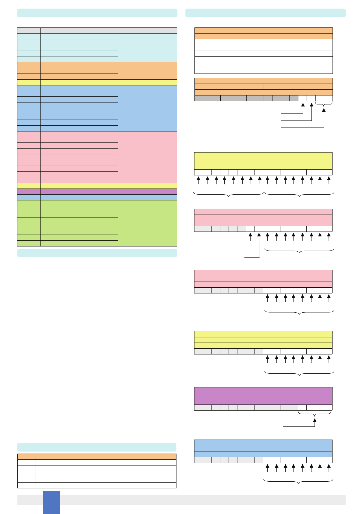
D5231E communicates via Modbus RTU RS-485 protocol. Below are all available registers.
Address Description Notes
0 G.M. Factory Code
Identification Data
1 Instrument Code
2 Option Code
3 Hardware Release
4 Software Release
16 Modbus Address
Communication Data17 Modbus Baudrate (1)
18 Modbus Format (1)
81 Input status of all channels (1) Input Data
96-111 Output 1 Source (2)
Output Configuration
112-127 Output 2 Source (2)
128-143 Output 3 Source (2)
144-159 Output 4 Source (2)
160-175 Output 5 Source (2)
176-191 Output 6 Source (2)
192-207 Output 7 Source (2)
208-223 Output 8 Source (2)
224 Output 1 Fault configuration (1)
225 Output 2 Fault configuration (1)
226 Output 3 Fault configuration (1)
227 Output 4 Fault configuration (1)
228 Output 5 Fault configuration (1)
229 Output 6 Fault configuration (1)
230 Output 7 Fault configuration (1)
231 Output 8 Fault configuration (1)
232 Fault on Bus (1)
233 Inputs configuration (1) Input Configuration
464 Commands execution (4) Command
548-555 Ch 1 (3)
Tags
556-563 Ch 2 (3)
564-571 Ch 3 (3)
572-579 Ch 4 (3)
580-587 Ch 5 (3)
588-595 Ch 6 (3)
596-603 Ch 7 (3)
604-611 Ch 8 (3)
Fault Configuration
520 Outputs Status Output Data
Supported Modbus parameters:
Each ModBus parameter is described by one 16-bit word.
(1) See command details on the right.
(2) Each Output can reflect the status of any Input.
In order to change Output Source fill Output Address range as shown below:
Input 1: All addresses contain value 43690.
Input 2: All addresses contain value 52428.
Input 3: All addresses contain value 61680.
Input 4: All addresses contain value 65280.
Input 5: Addresses contain:
0,65535,0,65535,0,65535,0,65535,0,65535,0,65535,0,65535,0,65535.
Input 6: Addresses contain:
0,0,65535,65535,0,0,65535,65535,0,0,65535,65535,0,0,65535,65535.
Input 7: Addresses contain:
0,0,0,0,65535,65535,65535,65535,0,0,0,0,65535,65535,65535,65535.
Input 8: Addresses contain:
0,0,0,0,0,0,0,0, 65535,65535,65535,65535,65535,65535,65535,65535.
(3) Tags are composed of 16 characters.
Each address contains 2 chars, starting from left.
(4) All configurations must be confirmed via Addr. 464, see details on the right.
Notes:
Supported functions:
Code Name Notes
03 read holding registers reads a stream of words from memory
04 read input registers reads a stream of words from memory
06 write single register writes a word in memory
16 write multiple registers writes a stream of words in memory
08 diagnostics: subcode 0 returns query data
Index Baudrate
0 4800
1 9600
2 19200
3 38400
4 57600
5 115200
Address 17: Supported ModBus Baudrates
Address 18: Supported ModBus Formats
High Byte Low Byte
Bit position
15 14 13 12 11 10 9 8 7 6 5 4 3 2 1 0
Termination resistance (1 = enabled)
Endianness 32 bit Data (0 = Little; 1 = Big)
Supported Modbus Parity:
0 8 data bit, no parity, 1 stop bit
1 8 data bit, even parity, 1 stop bit
2 8 data bit, odd parity, 1 stop bit
Address 81: Input status
High Byte Low Byte
Bit position
15 14 13 12 11 10 9 8 7 6 5 4 3 2 1 0
In 8 In 7 In 6 In 5 In 4 In 3 In 2 In 1
(0 = Off; 1 = On)
(0 = Ok; 1 = Fault)
Address 224 to 231: Output Fault Configuration
High Byte Low Byte
Bit position
15 14 13 12 11 10 9 8 7 6 5 4 3 2 1 0
(0 = None; 1 = Fault on Output)
Reflect status of Input Fault on Output
In case of Fault:
(0 = Go Off; 1 = Go On)
Contact status:
(0 = NO; 1 = NC)
Address 232: Output Fault on Bus Configuration
High Byte Low Byte
Bit position
15 14 13 12 11 10 9 8 7 6 5 4 3 2 1 0
(0 = None; 1 = Fault on BUS)
Reflect status of Input Fault on BUS
Address 233: Inputs Configuration
High Byte Low Byte
Bit position
15 14 13 12 11 10 9 8 7 6 5 4 3 2 1 0
(0 = Proximity; 1 = Dry contact)
In 8 In 7 In 6 In 5 In 4 In 3 In 2 In 1
Address 464: Commands
High Byte Low Byte
Bit position
15 14 13 12 11 10 9 8 7 6 5 4 3 2 1 0
1 Save Input/Output Configuration
2 Save Modbus configuration
8 Save Tags
Address 520: Outputs Data
High Byte Low Byte
Bit position
15 14 13 12 11 10 9 8 7 6 5 4 3 2 1 0
(0 = Open; 1 = Close)
Out
8
Out
7
Out
6
Out
5
Out
4
Out
3
Out
2
Out
1
Parameters details:
Table of contents
Popular Switch manuals by other brands

Micas
Micas M2-W6930-64QC Hardware installation and reference guide

Rose electronics
Rose electronics UltraMatrix AV HD Installation and operation manual

QNAP
QNAP QGD-1602P user guide

Sentera
Sentera SMT-D Mounting and operating instructions

IOGear
IOGear GCS1808 installation guide

Kensington
Kensington 33900 Instruction guide