GMC SIRAX TV 808-615 User manual

1
Aargauerstrasse 7
CH-5610 Wohlen/Switzerland
Phone +41 56 618 21 11
Fax +41 56 618 24 58
e-mail: [email protected]
http://www.gmc-instruments.com
Camille Bauer AG
TV 808-615/6/7/8 B d-f-e 136 839 12.00
Betriebsanleitung
SIRAX TV 808-615/6/7/8
Mode d’emploi
SIRAX TV 808-615/6/7/8
Operating Instructions
SIRAX TV 808-615/6/7/8

2

3
Sicherheitshinweise, die unbedingt beachtet wer-
den müssen, sind in dieser Betriebsanleitung mit
folgenden Symbolen markiert:
Lesconseilsdesécuritéquidoiventimpérativement
être observés sont marqués des symboles ci-
contre dans le présent mode d’emploi:
Thefollowingsymbols in the Operating Instructions
indicate safety precautions which must be strictly
observed:
Betriebsanleitung
Trennverstärker SIRAX TV 808-615/6/7/8
Deutsch
Français
English
Mode d’emploi
Amplificateur-Séparateur
SIRAX TV 808-615/6/7/8
Operating Instructions
Isolating amplifier
SIRAX TV 808-615/6/7/8

4
Deutsch
Betriebsanleitung
Trennverstärker SIRAX TV 808-615/6/7/8
Inhaltsverzeichnis
1. Erst lesen, dann... ...................................................... 4
2. Lieferumfang ............................................................... 4
3. Bestellangaben ........................................................... 4
4. Kurzbeschreibung ....................................................... 4
5. Übersicht der Funktionselemente ............................... 5
6. Technische Daten ....................................................... 5
7. Mechanische Codierung des Steck-Moduls............... 6
8. Elektrische Anschlüsse ............................................... 6
9. Montage ...................................................................... 7
10. Inbetriebnahme ........................................................... 8
11. Wartung ...................................................................... 8
12. Demontage-Hinweis ................................................... 8
13. Mass-Skizze ................................................................ 8
4. Kurzbeschreibung (z.B. Typ 808-6154 1A)
Der SIRAX TV 808 mit eigensicherem Ausgang und der
Funktion FSK-Durchgängigkeit wird zur Ansteuerung von
intelligenten I/P-Wandlern in explosionsgefährdeter Umge-
bung eingesetzt. Diese Wandler stellen zum Beispiel einen
Druck oder eine Ventilklappe in Funktion des eingeprägten
Ausgangsstromes (4…20 mA) ein. Der Hart-Bypass lässt
bidirektionale FSK-Signale in der Art des Hart-Protokolles
durch.
Die Hilfsenergie, der Eingang und der Ausgang sind galva-
nisch getrennt.
Trennverstärker (1)
1Codierkamm (2)
(zum Codieren des Geräteträgers SIRAX BP 902)
1Ex-Bescheinigung (3) (nur für Geräte in Ex-Ausführung)
1Betriebsanleitung (4), dreisprachig: Deutsch,
Französisch, Englisch
3. Bestellangaben
MERKMAL KENNUNG
1. Bauform
Gehäuse B17 808 - 6
2. Anzahl Kanäle
1 Kanal 1
3. Ausführung / Hilfsenergie
[EEx ia] IIC, 24 … 60 V DC/AC 5
Ausgang eigensicher
[EEx ia] IIC, 85 … 110 V DC/230 V AC 6
Ausgang eigensicher
Standard, 24 … 60 V DC/AC 7
Standard, 85 … 230 V DC/AC 8
4. Funktion
1 Eingang, 1 galvanisch getrennter 1
Ausgang
1 Eingang, 1 galvanisch getrennter 4
Ausgang, mit FSK-Durchgängigkeit
(Hart)
5. Eingangssignal
4 … 20 mA 1
Eingang [V] gemäss Typenschild 9
Eingang [mA] gemäss Typenschild Z
6. Ausgangssignal
4 … 20 mA A
0 … 20 mA B
20 … 4 mA invertiert C
20 … 0 mA invertiert D
1. Erst lesen, dann …
Der einwandfreie und gefahrlose Betrieb
setzt voraus, dass die Betriebsanleitung
gelesen und die in den Abschnitten
7. Mechanische Codierung des
Steck-Moduls
8. Elektrische Anschlüsse
9. Montage
10. Inbetriebnahme
enthaltenen Sicherheitshinweise beachtet werden.
Der Umgang mit diesem Gerät sollte nur durch entspre-
chend geschultes Personal erfolgen, das das Gerät kennt
und berechtigt ist, Arbeiten in regeltechnischen Anlagen
auszuführen.
2. Lieferumfang (Bild 1)
(1) (4) (3)
Aargauerstrasse 7
CH-5610 Wohlen/Switzerland
Telefon +41 56 618 21 11
Telefax +41 56618 24 58
Telex 827 901 cbm ch
Camille Bauer AG
TV 808-615/6/7/8 B d-f-e 000 000 06.98
Betriebsanleitung
SIRAX TV 808-615/6/7/8
Mode d’emploi
SIRAX TV 808-615/6/7/8
Operating Instructions
SIRAX TV 808-615/6/7/8
(2)

5
Deutsch
Bild 2
(5) Typenschild
(6) Schnellbefestigung
Rote Leuchtdiode ohne Funktion
ON Grüne Leuchtdiode für Betriebszustand
6. Technische Daten
Messeingang
Gleichstrom: Standardbereich 4…20 mA
Grenzwerte
0…0,1 bis 0…40 mA
auch live-zero,
Anfangswert > 0 bis ≤50% Endwert
– 0,1…0…+ 0,1 bis
– 20…0…+ 20 mA
max. Spanne: ≤40 mA
auch bipolar asymmetrisch
Ri= 15 Ω
Gleichspannung: Grenzwerte
0…0,06 bis 0…40 V
auch live-zero,
Anfangswert > 0 bis ≤50% Endwert
– 0,06…0…+ 0,06 bis
– 20…0…+ 20 V,
max. Spanne: ≤40 V
Ri= 100 kΩ
Überlastbarkeit: Gleichstrom
dauernd 2-fach
Gleichspannung
dauernd 2-fach
Messausgang
Gleichstrom: Standardbereiche
4…20 mA, 0…20 mA
invertiert
20…4 mA, 20…0 mA
Bürdenspannung /
Aussenwiderstand: Standard-Ausführung,
20 V / Rext. max. 1000 Ω
Ex-Ausführung,
15 V / Rext. max. 750 Ω
Strombegrenzung bei
Rext max.: Ca. 1,1 ×IAN
Spannungsbegrenzung
bei Rext = ∞: Ca. 26 V
Restwelligkeit des
Ausgangsstromes: < 0,5% p.p.
Einstellzeit: < 50 ms
Hilfsenergie H
Allstrom-Netzteil (DC und 45...400 Hz)
Tabelle 1: Nennspannungen und Toleranz-Angaben
Nennspannung Toleranz- Geräte
UNAngabe Ausführung
24... 60 V
DC / AC
85...230 V 1
DC / AC
24... 60 V DC – 15...+ 33%
DC / AC AC ±15%
85...230 V
AC
85...110 V
DC
DC –15...+ 33%
AC ±15%
Standard
(Nicht-Ex)
±10%
–15...+ 10%
In
Zündschutzart
Eigensicherheit
[EEx ia] IIC
1Bei DC-Hilfsenergie > 125 V sollte im Hilfsenergiekreis eine externe
Sicherung mit einem Abschaltvermögen von ≤20 A DC vorgesehen
werden.
Leistungsaufnahme: ≤1,2 W bzw. ≤3 VA
Genauigkeitsangaben (Analog DIN/IEC 770)
Grundgenauigkeit: Fehlergrenze ≤±0,2%
Linearitätsfehler und Reproduzier-
barkeit eingeschlossen
Umgebungsbedingungen
Inbetriebnahme: – 10 bis + 55 °C
Betriebstemperatur: – 25 bis + 55 °C, Ex* – 20 bis + 55 °C
Lagerungstemperatur: – 40 bis + 70 °C
Relative Feuchte
im Jahresmittel: ≤75%
(6)
(5)
ON
ohne
Funktion
5. Übersicht der Funktionselemente
Bild 2 zeigt die wichtigsten Teile, die im Zusammenhang mit
den elektrischen Anschlüssen und anderen in der Betriebs-
anleitung beschriebenen Vorgängen behandelt werden.
*AngabenderEG-Baumusterprüfbescheinigungfür den Geräteträger
SIRAX BP 902 mit der Zulassung PTB 97 ATEX 2113 beachten.

6
Deutsch
7. Mechanische Codierung des Steck-Moduls
Bild 4. Codierung des Steck-Moduls SIRAX TV 808 in
[EEx ia] IIC-Ausführung, Ausgang eigensicher.
Bild 3. Codierung des Steck-Moduls SIRAX TV 808 in Standard-
(Nicht Ex)-Ausführung.
Legende zu den Bildern 3 und 4:
= Mit Codiereinsatz, = Ohne Codiereinsatz
Bestell-Typ
808-617 808-618
Hilfsenergie
24…60 V DC/AC
A
B
C
D
E
F
G
H
I
K
L
M
Rückseite
A
B
C
D
E
F
G
H
I
K
L
M
Rückseite
Hilfsenergie
85…230 V DC/AC
Bestell-Typ
808-615 808-616
Hilfsenergie
24…60 V DC/AC
A
B
C
D
E
F
G
H
I
K
L
M
Rückseite
A
B
C
D
E
F
G
H
I
K
L
M
Rückseite
Hilfsenergie
85…110 V DC /
85…230 V AC
Wenn die Gefahr einer Verwechslung besteht, dass
Steck-Module in falsche Steckplätze gelangen kön-
nen, ist dies entsprechend EN 50 020, Abs. 6.3.2
auszuschliessen. Zu diesem Zweck sind die SIRAX
Steck-Module bereits ab Werk mit Codierein-
sätzen gemäss Bilder 3 und 4 ausgestattet.
8. Elektrische Anschlüsse
Der Trennverstärker SIRAX TV 808 wird auf einen Geräteträ-
ger BP 902 aufgesteckt. Die elektrische Verbindung zwi-
schen Trennverstärker und Geräteträger erfolgt über einen
96-poligen Steckverbinder (Bauform C, DIN 41 612). Die
Steckerbelegung geht aus Bild 5 hervor.
Die Anschlussbelegung des Geräteträgers entnehmen
Sie bitte unserer Betriebsanleitung für den Geräteträger.
Unbedingt sicher stellen, dass die Leitungen
beim Anschliessen spannungsfrei sind!
Möglicherweise drohende Gefahr,
230 V Netzspannung als Hilfsenergie!
Ferner ist zu beachten, …
… dass die Daten, die zur Lösung der Messaufga-
be erforderlich sind, mit denen auf dem Typen-
schild des SIRAX TV 808 übereinstimmen
(Messeingang, Messausgang,
Hilfsenergie!)
… dass der Gesamtwiderstand in der Messaus-
gangsleitung (in Serie geschaltete Empfangs-
geräte plus Leitung) den maximalen Aussen-
widerstand Rext. max. nicht überschreitet!
Rext. max. siehe «Messausgang», Abschnitt
«6. Technische Daten»!
… dass die Messeingangs- und Messausgangs-
leitungen als verdrillte Kabel und möglichst
räumlich getrennt von Starkstromleitungen
verlegt werden!
Im übrigen landesübliche Vorschriften (z.B. für
Deutschland DIN VDE 0100 «Bestimmungen für
das Errichten von Starkstromanlagen mit Nenn-
spannungen bis 1000 V») bei der Installation und
Auswahl des Materials der elektrischen
Leitungen befolgen!
Bei Geräten in der Zündschutzart «Eigen-
sicherheit» [EEx ia] IIC sind zusätzlich die
Angaben der Baumusterprüfbescheinigung,
die EN 60 079-14, sowie die nationalen Vor-
schriften für die Errichtung von elektrischen
Anlagenin explosionsgefährdeten Bereichen
zu berücksichtigen.

7
Deutsch
Bild 5. Steckerbelegung. Sicht auf die Rückseite des
SIRAX TV 808-61.. ..
Legende zu Bild 5:
E = Messeingang
A = Messausgang
H = Hilfsenergie
HHT = Anschlussmöglich-
keit eines Hand-
Held-Terminals
Rückseite
cab
2
3
4
5
6
7
8
14
20
26
27
28
29
30
31
32
1
E
–
–
+
+
A
H
(+) ~
(–) ~
–
+HHT
FSK
8.1 Anschluss des Hand-Held-Terminals HHT
Der Trennverstärker SIRAX TV 808 kann in der Ausführung
FSK-Durchgängigkeit ein frequenzmoduliertes Digitalsignal
übertragen. Hand-Held-Terminal HHT an die Stifte a26 (–)
und a28 (+) gemäss Bild 5 anschliessen.
8.2 Anschluss der Messeingangsleitungen
Eingangsleitungen an die Stifte c27 (–) und c29 (+) gemäss
Bild 5 anschliessen.
8.3 Anschluss der Messausgangsleitungen
Ausgangsleitungen a1 (–) und a3 (+) anschliessen.
Beachten, dass der zulässige Aussenwiderstand Rext max.
des Trennverstärkers eingehalten wird (siehe Ab-
schnitt «6. Technische Daten»).
8.4 Anschluss der Hilfsenergieleitungen
Hilfsenergieleitungen an die Stifte a20 ( ) und c14 ( ) ge-
mäss Bild 5 anschliessen.
Falls sich die Hilfsenergie für den SIRAX TV 808 ausschalten
lassen soll, ist in der Zuleitung für die Hilfsenergie ein zwei-
poliger Schalter anzuordnen.
Hinweis: Bei DC-Hilfsenergie > 125 V muss im Hilfsenergie-
kreis eine externe Sicherung mit einem Abschalt-
vermögen von ≤20 A DC vorgesehen werden.
~
+
~
–
9. Montage
Der Trennverstärker SIRAX TV 808 wird auf einen Geräteträ-
ger BP 902 aufgesteckt.
Bei der Festlegung des Montageortes (Messortes)
ist zu beachten, dass die Grenzen der Betriebs-
temperatur nicht überschritten werden:
– 25 und + 55 °C bei Standard-Geräten
–20und + 55 °C bei Ex-Geräten!
SIRAX
GOSSEN
METRAWATT
CAMILLEBAUER
3.
GOSSEN
GOSSEN
METRA
METRAWATT
TT
CAM
AMILLEBAUER
LLEBAUER
SIRAX
1.
2.
Bild 6. Steck-Modul aufstecken.
9.1 Steck-Modul auf Geräteträger aufstecken
Vor dem Einstecken des SIRAX TV 808 in den
Geräteträger unbedingt sicher stellen, …
… dass die Elektrischen Anschlüsse des
GeräteträgersmitdemAnschlussplandes
Steck-Moduls übereinstimmen
… dass der Geräteträger gemäss Ab-
schnitt «Mechanische Codierung des
Geräteträgers» richtig codiert ist. Be-
triebsanleitung des Geräteträgers be-
achten.
… dass bei SIRAX Steck-Modulen mit
24…60 V DC/AC Hilfsenergie der Co-
diereinsatz B aus dem Geräteträger
entfernt werden muss. Dass die Hilfs-
energiequelle den richtigen Klein-
spannungswert führt.
1. Steck-Modul auf Federleiste aufstecken.
2. Schnellverschluss bei vertikaler Einbaulage des Geräte-
trägers in vertikale Position bringen, bei horizontaler
Einbaulage in horizontale Lage stellen.
3. Schnellverschluss mit Schraubendreher eindrücken, bis
dieser hörbar einrastet.

8
10. Inbetriebnahme
Messeingang und Hilfsenergie einschalten. Nach dem Ein-
schalten der Hilfsenergie leuchtet die grüne Leuchtdiode
dauernd.
Beim Einschalten der Hilfsenergie muss die Hilfs-
energiequelle kurzzeitig genügend Strom abge-
ben können. Die Trennverstärker benötigen näm-
lich einen Anlaufstrom IAnlauf von …
…I
Anlauf ≥160 mA bei der Ausführung mit dem
Hilfsenergie-Bereich 24 – 60 V DC/AC
oder
…I
Anlauf ≥35 mA bei der Ausführung mit dem
Hilfsenergie-Bereich 85 – 230 V DC/AC
11. Wartung
Der Trennverstärker ist wartungsfrei.
12. Demontage-Hinweis
1. Schnellverschluss um 90°drehen.
2. Steck-Modul herausziehen.
SIRAX
GOSSEN
METRAWATT
CAMILLEBAUER
2.
1.
Bild 8. SIRAX TV 808 im Gehäuse B17.
13. Mass-Skizze
110
135,7 15 18
103,3
123,5
113,5
150,7
+0
–0,5
Bild 7. Steck-Modul herausziehen.
Deutsch

9
Français
Mode d’emploi
Amplificateur-Séparateur SIRAX TV 808-615/6/7/8
Sommaire
1. A lire en premier, ensuite... ........................................ 9
2. Etendue de la livraison ................................................ 9
3. Références de commande .......................................... 9
4. Description brève ........................................................ 9
5. Illustration des éléments fonctionnels ...................... 10
6. Caractéristiques techniques ..................................... 10
7. Codage mécanique du module embrochable .......... 11
8. Raccordements électriques ...................................... 11
9. Montage .................................................................... 12
10. Mise en service ......................................................... 13
11. Entretien .................................................................... 13
12. Instructions pour le démontage ................................ 13
13. Croquis d’encombrement ......................................... 13
4. Description brève (p. ex. type 808-6154 1A)
Le SIRAX TV 808 avec sortie en sécurité intrinsèque et
permettant la transmission de la communication FSK
(Frequency Shift Keying) est principalement utilisé pour la
conduite de convertisseur électropneumatique du type «in-
telligent-smart». Ces convertisseurs seront installés en
ambianceavec risque d’explosions. Le convertisseur électro-
pneumatique en fonction du courant (4…20 mA), produira
une pression ou agira sur la commande d’une vanne. Un
«Bypass»incorporépermetdedialoguerparlacommunication
FSK en protocole HART (Highway Addressable Remote
Transducer).
Les circuits de l’alimentation auxiliaire, du signal d’entrée et
du signal de sortie sont isolés entre eux.
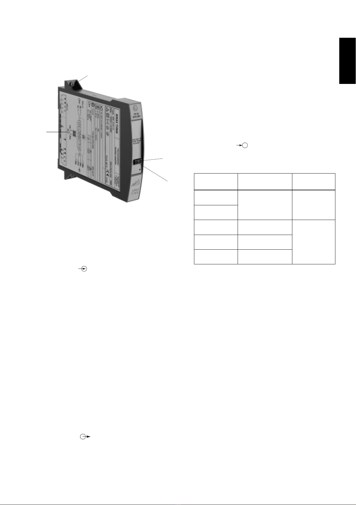
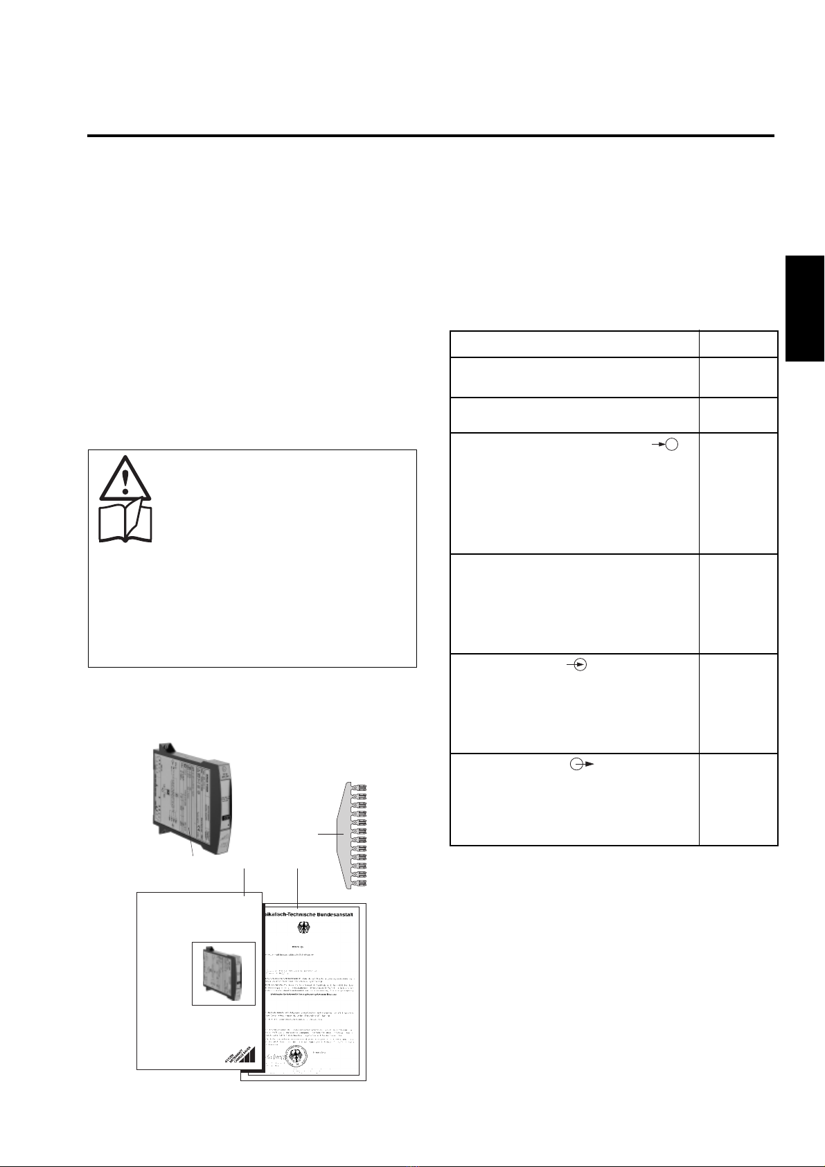
Amplificateur de séparation (1)
1Barre de codage (2)
(pour le codage du support d’appareils SIRAX BP 902)
1Attestation Ex (3) (seulement pour appareils en
exécution Ex)
1Mode d’emploi (4) en trois langues: allemand, français
et anglais
3. Références de commande
CARACTERISTIQUE CODE
1. Construction
Boîtier B17 808 - 6
2. Nombre des canaux
1 canal 1
3. Exécution / Alimentation aux.
[EEx ia] IIC, 24 … 60 V CC/CA 5
Sortie en sécurité intrinsèque
[EEx ia] IIC, 85 … 110 V CC/230 V CA 6
Sortie en sécurité intrinsèque
Standard, 24 … 60 V CC/CA 7
Standard, 85 … 230 V CC/CA 8
4. Fonction
1 entrée, 1 sortie en séparation 1
galvanique
1 entrée, 1 sortie en séparation 4
galvanique, avec transmission de la
communication (HART)
5. Signal d’entrée
4 … 20 mA 1
Entrée [V] 9
selon plaquette signalétique
Entrée [mA] Z
selon plaquette signalétique
6. Signal de sortie
4 … 20 mA A
0 … 20 mA B
20 … 4 mA inversé C
20 … 0 mA inversé D
1. A lire en premier, ensuite …
Pour un fonctionnement sûr et sans danger,
il est essentiel de lire le présent mode
d’emploi et de respecter les recommanda-
tions de sécurité mentionnées dans les
rubriques
7. Codage mécanique du module
embrochable
8. Raccordements électriques
9. Montage
10. Mise en service.
Ces appareils devraient uniquement être manipulés par
des personnes qui les connaissent et qui sont autorisées
à travailler sur des installations techniques du réglage.
2. Etendue de la livraison (Fig. 1)
(1) (4) (3)
Aargauerstrasse 7
CH-5610 Wohlen/Switzerland
Telefon +41 56 618 21 11
Telefax +41 56618 24 58
Telex 827 901 cbm ch
Camille Bauer AG
TV 808-615/6/7/8 B d-f-e 000 000 06.98
Betriebsanleitung
SIRAX TV 808-615/6/7/8
Mode d’emploi
SIRAX TV 808-615/6/7/8
Operating Instructions
SIRAX TV 808-615/6/7/8
(2)

10
Français
Fig. 2
(5) Plaquette signalétique
(6) Fixation rapide
Diode luminescente rouge sans fonction
ON Diode luminescente verte pour état des fonctionnement
6. Caractéristiques techniques
Entrée de mesure
Courant continu: Etendues standards 4…20 mA
Valeurs limites
0…0,1 à 0…40 mA
également live-zéro,
valeur début > 0 à ≤50% valeur fin
– 0,1…0…+ 0,1 à
– 20…0…+ 20 mA
plage max.: ≤40 mA
également bipolaire asymétrique
Ri= 15 Ω
Tension continue: Valeurs limites
0…0,06 à 0…40 V
également live-zéro,
valeur début > 0 à ≤50% valeur fin
– 0,06…0…+ 0,06 à
– 20…0…+ 20 V,
plage max.: ≤40 V
Ri= 100 kΩ
Surcharge: Courant continu
en permanence 2 fois
Tension continue
en permanence 2 fois
Sortie de mesure
Courant continu: Etendues standards
4…20 mA, 0…20 mA
inversé
20…4 mA, 20…0 mA
Tension de charge /
Résistance extérieure: Exécution standard,
20 V / Rext. max. 1000 Ω
Exécution Ex,
15 V / Rext. max. 750 Ω
Limitation de courant
en Rext max.: Env. 1,1 ×IAN
Limitation de tension
en Rext = ∞: Env. 26 V
Ondulation résiduelle
du signal de sortie: < 0,5% p.p.
Temps de réponse: < 50 ms
Alimentation auxiliaire H
Bloc d’alimentation tous-courants (CC et 45...400 Hz)
Tableau 1: Tensions nominales et tolérances
Tension nominale Tolérance Exécution des
UNappareils
24... 60 V
CC / CA
85...230 V 1
CC / CA
24... 60 V CC – 15...+ 33%
CC / CA CA ±15%
85...230 V
CA
85...110 V
CC
CC –15...+ 33%
CA ±15%
Standard
(Non-Ex)
±10%
–15...+ 10%
En
sécurité
intrinsèque
[EEx ia] IIC
1Pour une alimentation auxiliaire > 125 V CC, il faut équiper le circuit
d’alimentation d’un fusible externe avec un pouvoir de coupure de
≤20 A CC.
Consommation: ≤1,2 W resp. ≤3 VA
Précision (selon analogie DIN/CEI 770)
Précision de base: Limite d’erreur ≤±0,2%
Erreurs types de linéarité et de
reproductibilité comprises
Ambiance extérieure
Mise en service: – 10 à + 55 °C
Température de
fonctionnement: – 25 à + 55 °C, Ex* – 20 à + 55 °C
Température de
stockage: – 40 à + 70 °C
Humidité relative en
moyenne annuelle: ≤75%
(6)
(5)
ON
sans
fonction
5. Illustration des éléments fonctionnels
La Fig. 2 présente les parties les plus importantes d’amplifi-
cateur de séparation qui sont décrites ci-après et qui concer-
nent les raccordements électriques et les autres détails
mentionnés dans le présent mode d’emploi.
* Respecter les données de l’attestation de conformité pour support
d’appareils SIRAX BP 902 selon homologation PTB 97 ATEX 2113.

11
Français
7.Codage mécanique dumodule embrochable
Fig. 4. Codage du module embrochable SIRAX TV 808 en
exécution [EEx ia] IIC, sortie en sécurité intrinsèque.
Fig. 3. Codage du module embrochable SIRAX TV 808 en
exécution standard (non-Ex).
Légende pour les Figs. 3 et 4:
= Avec bouchon de codage, = Sans bouchon de codage
Type de commande
808-617 808-618
Alimentation auxiliaire
24…60 V CC/CA
A
B
C
D
E
F
G
H
I
K
L
M
Face arrière
A
B
C
D
E
F
G
H
I
K
L
M
Face arrière
Alimentation auxiliaire
85…230 V CC/CA
Type de commande
808-615 808-616
Alimentation auxiliaire
24…60 V CC/CA
A
B
C
D
E
F
G
H
I
K
L
M
Face arrière
A
B
C
D
E
F
G
H
I
K
L
M
Face arrière
Alimentation auxiliaire
85…110 V CC /
85…230 V CA
En cas de risque d’embrocher les appareils dans une
place inappropriée, la norme EN 50020, chapitre
6.3.2 prescrit l’élimination de ce risque. A cette fin,
les modules embrochables SIRAX comportent
d’office des bouchons de codage selon Fig. 3 et 4.
8. Raccordements électriques
L’amplificateur de séparation SIRAX TV 808 est embroché
dans un support d’appareils BP 902. Les connexions
électriques entre l’amplificateur de séparation et le support
sont assurées par un connecteur à 96 pôles (forme C,
DIN 41 612). Le plan des fiches utilisées est représente dans
la Fig. 5.
Le schéma de raccordement du support d’appareils peut
être consulté dans notre mode d’emploi BP 902.
Lorsduraccordement des câbles, se rassurer
impérativement que toutes les lignes soient
hors tension!
Danger imminent de 230 V alimentation
auxiliaire!
Veuiller en plus, …
… que les caractéristiques techniques qui
permettent de résoudre le problème de mesure
correspondent aux données mentionnées sur
la plaquette signalétique du SIRAX TV 808
(entrée de mesure, sortie de mesure,
alimentation auxiliaire!)
… que la résistance totale du circuit de sortie de
mesure (instruments récepteurs connectés en
série plus résistance des lignes) n’excède pas
la valeur maximum Rext., mentionnée sous
«sortiedemesure»du chapitre «6. Caractéristi-
ques techniques»!
… que les lignes d’entrée de mesure et de sortie
de signal de mesure soient réalisées par des
câbles torsadés et disposées à une certaine
distance des lignes courant fort!
Au reste, respecter les prescriptions nationales
pour l’installation et le choix du matériel des
conducteurs électriques!
Pour les appareils en mode de protection «à
sécurité intrinsèque» [EEx ia] IIC il faut
respecter les indications contenues dans
l’attestation de conformité EN 60 079-14
ainsi que les prescriptions nationales pour la
réalisation d’installations électriques dans
des enceintes avec danger d’explosions!

12
Français
Fig. 5. Plan des fiches. Vue depuis l’arrière du SIRAX TV 808-61.. ..
Légende pour la Fig. 5:
E = Entrée de mesure
A = Sortie de mesure
H = Alimentation
auxiliaire
HHT = Raccordement
possible, bien que
peu usuel, d’un
élément portable de
communication
Face arrière
cab
2
3
4
5
6
7
8
14
20
26
27
28
29
30
31
32
1
E
–
–
+
+
A
H
(+) ~
(–) ~
–
+HHT
FSK
8.1 Raccordement de l’élément portable de com-
munication HHT
Dans la version FSK avec transmission de communication,
l’amplificateur de séparation SIRAX TV 808 peut faire passer
un signal numérique en modulation de fréquence. L’élément
portable de communication HHT doit être raccordé aux
doigts a26 (–) et a28 (+) comme indiqué dans la Fig. 5.
8.2 Raccordement des entrées
Les lignes d’entrées doivent être raccordées aux doigts c27
(–) et c29 (+) selon Fig. 5.
8.3 Raccordement des lignes de sortie de mesure
Connecter les lignes de la sortie aux doigts a1 (–) et a3 (+).
Attention! La résistance extérieure Rext max. admise par
l’amplificateur de séparation ne doit pas être
dépassée (voir rubrique «6. Caractéristiques
techniques»).
8.4 Raccordement des lignes de l’alimentation
auxiliaire
Les lignes de l’alimentation auxiliaire doivent être raccordées
aux doigts a20 ( ) et c14 ( ).
Si l’on désire pouvoir interrompre l’alimentation auxiliaire du
SIRAX TV 808, il faut intercaler un interrupteur bipolaire dans
le circuit d’alimentation.
Avertissement: Pourune alimentation auxiliaire > 125 V CC,
il faut equiper le circuit d’alimentation d’un
fusible externe avec un pouvoir de coupure
de ≤20 A CC.
~
+
~
–
9. Montage
L’amplificateur de séparation SIRAX TV 808 est embroché
dans un support d’appareils BP 902.
Pour la détermination de l’endroit de montage
(endroit de mesure) il faut faire attention que les
valeurs limites de la température de fonctionne-
ment ne soient pas dépassées:
– 25 et + 55 °C en appareils standards
–20et + 55 °C en appareils Ex!
SIRAX
GOSSEN
METRAWATT
CAMILLEBAUER
3.
GOSSEN
GOSSEN
METRA
METRA
WATT
TT
CAM
AM
ILLEBAUER
LLEBAUER
SIRAX
1.
2.
Fig. 6. Enficher le module embrochable.
9.1Monter le module embrochable dans un support
d’appareils
Avant d’embrocher le SIRAX TV 808 dans le
support d’appareils, vérifier sans faute, …
… la concordance des raccordements
électriques du support et du plan de
bornes du module embrochable
… le codage correct du support d’appa-
reils selon chapitre «Codage méca-
niquedusupportd’appareils». Respec-
ter les indications du mode d’emploi
du support d’appareils.
… que pour des modules embrochables
SIRAX avec alimentation auxiliaire
24…60VCC/CA, le bouchon decodage
B du support d’appareils soit enlevé et
que la source d’alimentation fournisse
la faible tension correcte.
1. Enficher le module embrochable.
2. Amener la fixation rapide dans la position verticale pour
montage vertical de l’appareil, dans la position horizon-
tale pour montage horizontal.
3. Enfoncer à l’aide d’un tournevis la fixation rapide jusqu’à
ce que l’on entende l’encliquetage.

13
Français
10. Mise en service
Enclencher le circuit d’entrée de mesure et l’alimentation
auxiliaire. Après l’enclenchement de la tension auxiliaire, la
diode verte reste allumée en permanence.
Lors de l’enclenchement de l’énergie auxiliaire de
l’amplificateur de séparation, la source d’alimenta-
tion doit fournir pendant un court laps de temps en
courant suffisamment élevé, ceci du fait que le
SIRAX TV 808 nécessite un courant de démarrage
Idémarrage de …
…I
démarrage ≥160 mA pour la version avec le bloc
d’alimentation auxiliaire 24 – 60 V CC/CA
ou
…I
démarrage ≥35 mA pour la version avec le bloc
d’alimentation auxiliaire 85 – 230 V CC/CA
11. Entretien
L’amplificateur de séparation ne nécessite pas d’entretien.
12. Instructions pour le démontage
1. Tourner la fixation rapide de 90°.
2. Retirer le module embrochable.
SIRAX
GOSSEN
METRAWATT
CAMILLEBAUER
2.
1.
Fig. 8. SIRAX TV 808 en boîtier B17.
13. Croquis d’encombrement
110
135,7 15 18
103,3
123,5
113,5
150,7
+0
–0,5
Fig. 7. Retirer le module embrochable.

14
English
Operating Instructions
Isolating amplifier SIRAX TV 808-615/6/7/8
Contents
1. Read first and then................................................... 14
2. Scope of supply ........................................................ 14
3. Ordering informations ............................................... 14
4. Brief description ........................................................ 14
5. Overview of the parts ................................................ 15
6. Technical data........................................................... 15
7. Mechanical coding of the plug-in module ................ 16
8. Electrical connections ............................................... 16
9. Mounting ................................................................... 17
10. Commissioning ......................................................... 18
11. Maintenance ............................................................. 18
12. Releasing the isolation amplifier ............................... 18
13. Dimensional drawing................................................. 18
4. Brief description (e.g. type 808-6154 1A)
The SIRAX TV 808 has an intrinsically safe output and an
FSK continuity function and is used to control intelligent
input transducers in explosion hazard areas. The transducers
adjust, for example, a pressure or the position of a valve in
relation to the impressed output current (4…20 mA). The Hart
bypass permits bi-directional FSK signals to pass according
to the Hart protocol.
The power supply and the inputs and outputs are electrically
insulated.
Isolating amplifier (1)
1Coding comb (2)
(for coding the backplane SIRAX BP 902)
1Ex approval (3) (for instruments in Ex version only)
1Operating Instructions (4) in three languages: German,
French, English
3. Ordering informations
DESCRIPTION MARKING
1. Mechanical design
Housing B17 808 - 6
2. Number of channels
1 channel 1
3. Version / Power supply
[EEx ia] IIC, 24 … 60 V DC/AC 5
Output intrinsically safe
[EEx ia] IIC, 85 … 110 V DC/230 V AC 6
Output intrinsically safe
Standard, 24 … 60 V DC/AC 7
Standard, 85 … 230 V DC/AC 8
4. Function
1 input, 1 electrically insulated output 1
1 input, 1 electrically insulated 4
output, designed for FSK*
communication (HART)
5. Input signal
4 … 20 mA 1
Input [V] acc. to type label 9
Input [mA] acc. to type label Z
6. Output signal
4 … 20 mA A
0 … 20 mA B
20 … 4 mA invert C
20 … 0 mA invert D
1. Read first and then …
The proper and safe operation of the device
assumes that the Operating Instructions are
read and the safety warnings given in the
various Sections
7. Mechanical coding of the
plug-in module
8. Electrical connections
9. Mounting
10. Commissioning
are observed.
The device should only be handled by appropriately
trained personnel who are familiar with it and authorised
to work in electrical installations.
2. Scope of supply (Fig. 1)
* FSK = Frequency Shift Keying
(1) (4) (3)
Aargauerstrasse 7
CH-5610 Wohlen/Switzerland
Telefon +41 56 618 21 11
Telefax +41 56618 24 58
Telex 827 901 cbm ch
Camille Bauer AG
TV 808-615/6/7/8 B d-f-e 000 000 06.98
Betriebsanleitung
SIRAX TV 808-615/6/7/8
Mode d’emploi
SIRAX TV 808-615/6/7/8
Operating Instructions
SIRAX TV 808-615/6/7/8
(2)

15
English
Fig. 2
(5) Type label
(6) Fastener
Red LED without function
ON Green LED for indicating device standing by
6. Technical data
Measuring input
DC current: Standard range 4…20 mA
Limit values
0…0.1 to 0…40 mA
also live zero,
start value > 0 to ≤50% final value
– 0.1…0…+ 0.1 to
– 20…0…+ 20 mA
max. span: ≤40 mA
also bipolar asymmetrical
Ri= 15 Ω
DC voltage: Limit values
0…0.06 to 0…40 V
also live zero,
start value > 0 to ≤50% final value
– 0.06…0…+ 0.06 to
– 20…0…+ 20 V,
max. span: ≤40 V
Ri= 100 kΩ
Overload capacity: DC current
continuously 2-fold
DC voltage
continuously 2-fold
Measuring output
DC current: Standard ranges
4…20 mA, 0…20 mA
invert
20…4 mA, 20…0 mA
Burden voltage /
external resistance: Standard version,
20 V / Rext. max. 1000 Ω
Ex version,
15 V / Rext. max. 750 Ω
Current limiter at
Rext max.: Approx. 1.1 ×IAN
Voltage limiter at
Rext = ∞: Approx. 26 V
Residual ripple in
output current: < 0.5% p.p.
Response time: < 50 ms
Power supply H
AC/DC power pack (DC and 45...400 Hz)
Table 1: Nominal voltages and tolerances
Nominal voltage Tolerance Instruments
UNversion
24... 60 V
DC / AC
85...230 V 1
DC / AC
24... 60 V DC –15...+ 33%
DC / AC AC ±15%
85...230 V
AC
85...110 V
DC
DC –15...+ 33%
AC ±15%
Standard
(Non-Ex)
±10%
–15...+ 10%
In
type of
protection
intrinsically safe
[EEx ia] IIC
1For power supply > 125 V, the auxiliary circuit should include an
external fuse with a rating ≤20 A DC.
Power input: ≤1.2 W resp. ≤3 VA
Accuracy data (acc. to DIN/IEC 770)
Basic accuracy: Limit error ≤±0.2%
Including linearity and reproduci-
bility errors
Environmental conditions
Commissioning
temperature: – 10 to + 55 °C
Operating temperature: – 25 to + 55 °C, Ex* – 20 to + 55 °C
Storage temperature: – 40 to + 70 °C
Annual mean
relative humidity: ≤75%
(6)
(5)
ON
without
function
5. Overview of the parts
Figure 2 shows those parts of the device of consequence for
electrical connections and other operations described in the
Operating Instructions.
* The data of the EC-Type Examination Certificate for backplane
SIRAX BP 902 with admission PTB 97 ATEX 2113 should be noted.

16
English
7. Mechanical coding of the plug-in module
Fig. 4. Coding of the plug-in module SIRAX TV 808 in
[EEx ia] IIC version, output intrinsically safe.
Fig. 3. Coding of the plug-in module SIRAX TV 808 in standard
(non-Ex) version.
Legend to Fig. 3 and 4:
= With set of code, = Without set of code
Order Type
808-617 808-618
Power supply
24…60 V DC/AC
A
B
C
D
E
F
G
H
I
K
L
M
Back
A
B
C
D
E
F
G
H
I
K
L
M
Back
Power supply
85…230 V DC/AC
Order Type
808-615 808-616
Power supply
24…60 V DC/AC
A
B
C
D
E
F
G
H
I
K
L
M
Back
A
B
C
D
E
F
G
H
I
K
L
M
Back
Power supply
85…110 V DC /
85…230 V AC
Where there is a danger of inserting a module in the
wrong slot, the possibility has to be excluded as
prescribed in EN 50 020, Section 6.3.2. To this end,
the units must be supplied already equipped with
coding inserts as shown in Figure 3 and 4.
8. Electrical connections
The isolating amplifier SIRAX TV 808 is plugged onto a
backplane BP 902. A 96 pin connector (model C, DIN 41 612)
establishes the electrical connections between the isolating
amplifier and the backplane. The pin connections can be
seen from Fig. 5.
Please refer to our backplane instructions for the back-
plane wiring.
Make sure that the cables are not live when
making the connections!
The 230 V power supply is potentially
dangerous!
Note that, …
… the data required to carry out the prescribed
measurement must correspond to those
marked on the nameplate of SIRAX TV 808
(measuring input, measuring output,
power supply!)
… thetotalloopresistance connected to the output
(receiver plus leads) does not exceed the
maximum permissible value Rext. max., see
“Measuring output” in Section “6. Technical
data” for the maximum values of Rext.!
… the measurement input and output cables
should be twisted pairs and run as far as
possible away from heavy current cables!
In all other respects, observe all local regulations
when selecting the type of electrical cable and
installing them!
In the case of “Intrinsically safe” explosion-
proofversions [EEx ia]IIC, the supplementary
information given on the type examination
certification, the EN 60 079-14, and also
local regulations applicable to electrical
installation in explosion hazard areas must
be taken into account.

17
English
Fig. 5. Plug arrangement seen from the rear of
SIRAX TV 808-61.. ..
Legend to Fig. 5:
E = Measuring input
A = Measuring output
H = Power supply
HHT = Connection of an
Hand-Held-
Terminal
Back
cab
2
3
4
5
6
7
8
14
20
26
27
28
29
30
31
32
1
E
–
–
+
+
A
H
(+) ~
(–) ~
–
+HHT
FSK
8.1 Connection of the hand-held terminal HHT
The FSK version of the isolating amplifier SIRAX TV 808 can
transmit a frequency modulated digital signal. Connect the
hand-held terminal HHT to the pins a26 (–) and a28 (+) as
shown in Fig. 5.
8.2 Connecting the measuring input leads
Connect the input leads to the pins c27 (–) and c29 (+) as
shown in Fig. 5.
8.3 Connecting the measuring output leads
Connect the measuring output leads to pins a1 (–) and a3 (+).
Note: Take care that the amplifier’s maximum permissible
external burden Rext. is not exceeded (see Section
“6. Technica data”).
8.4 Connecting the power supply leads
Connect the power supply leads to pins a20 ( ) and c14 ( )
as shown in Fig. 5.
A two-pole switch must be included in the supply connection
where facility for switching SIRAX TV 808 off is desired.
Note: An external supply fuse with a rupture capacity
≤20 A must be provided for DC supply voltages
> 125 V.
~
+
~
–
9. Mounting
The isolating amplifier SIRAX TV 808 is plugged onto a
backplane BP 902.
When deciding where to install the isolating
amplifier (measuring location), take care that the
limits of the operating temperature are kept:
– 25 and + 55 °C for standard instruments
–20and + 55 °C for Ex instruments!
Fig. 6. Plug the module into the base.
9.1 Plugging the module into the backplane
Before inserting the SIRAX TV 808 into the
backplane, ensure that, …
… the backplane wiring is in strict accord-
ance with the wiring diagram of the
module
… the backplane is coded correctly
according to the section entitled
“Mechanicalcoding of the backplane”.
Read the instructions for the back-
plane.
… The red coding insert has been re-
moved from the backplane for SIRAX
plug-in modules with a power supply
of 24…60 V DC/AC and that the power
supply is correct for the module.
1. Clip the module base onto the top-hat rail.
2. If the backplane is mounted vertically, turn the quick
release screws on the module to a vertical position,
respectively if it is mounted horizontally, turn the screws to
a horizontal position.
3. Press the quick release screws inwards with the screw-
driver until there is an audible click.
SIRAX
GOSSEN
METRAWATT
CAMILLEBAUER
3.
GOSSEN
GOSSEN
METRA
METRAWATT
TT
CAM
AMILLEBAUER
LLEBAUER
SIRAX
1.
2.

18
English
10. Commissioning
Switch on the measuring input and the power supply. The
green LED lights continuously after switching on.
Thepower supply unit must becapable of supplying
a brief current surge when switching on. The
isolating amplifier presents a low impedance at
the instant of switching which requires a current
Istart of …
…I
start ≥160 mA for the version with a power
supply range of 24 – 60 V DC/AC
or
…I
start ≥35 mA for the version with a power supply
range of 85 – 230 V DC/AC
11. Maintenance
No maintenance is required.
12. Releasing the isolating amplifier
1. Rotate the quick release screws 90°.
2. Withdraw the plug-in module.
SIRAX
GOSSEN
METRAWATT
CAMILLEBAUER
2.
1.
Fig. 8. SIRAX TV 808 in housing B17.
13. Dimensional drawing
110
135,7 15 18
103,3
123,5
113,5
150,7
+0
–0,5
Fig. 7. Withdraw the module from the base.

19

20
This manual suits for next models
3
Table of contents
Languages:
Other GMC Measuring Instrument manuals