Table of contents
FUS1010 IP65 NEMA 4X & IP66 NEMA 7 Quick Start
4 Operating Instructions, 01/2013, A5E03086486-AC
Table 5- 1 Troubleshooting Tips....................................................................................................................49
Table 5- 2 Alarm Codes and Descriptions ....................................................................................................51
Table A- 1 Connection Diagrams and Part Numbers ....................................................................................53
Table A- 2 Input/Output Wiring (TB2) - 7ME39400AL00 and 7ME39400AL01 I/O Module (for
7ME3500 or 7ME3530 only) ........................................................................................................54
Table A- 3 Input/Output Wiring (TB3) - 7ME39400AL00 and 7ME39400AL01 I/O Module ..........................55
Table A- 4 Connection Diagrams and Part Numbers ....................................................................................56
Table A- 5 Input/Output Wiring (TB2) - 7ME39400AL03 and 7ME39400AL04 Expanded I/O Module.........57
Table A- 6 Input/Output Wiring (TB3) - 7ME39400AL03 and 7ME39400AL04 Expanded I/O Module.........59
Table A- 7 Input/Output Wiring (TB4) - 7ME39400AL03 and 7ME39400AL04 Expanded I/O Module.........60
Table A- 8 Connection Diagrams and Part Numbers ....................................................................................61
Table A- 9 Input/Output Wiring (TB2) - 7ME39400AL04 Expanded I/O Module...........................................62
Table A- 10 Open Collector User Resistor Recommendations .......................................................................63
Table A- 11 Input/Output Wiring (TB3) - 7ME39400AL04 Expanded I/O Module...........................................63
Table A- 12 Input/Output Wiring (TB4) - 7ME39400AL04 Expanded I/O Module...........................................65
Table A- 13 Input/Output Wiring (TB3) - 7ME39406ML00 I/O Module (4-Channel) .......................................66
Table A- 14 Connection Diagrams and Part Numbers ....................................................................................67
Table A- 15 Input/Output Wiring TB1 7ME39404SB00 - Analog Input Module (2 Chan/Dual Path)...............68
Table A- 16 Input/Output Wiring TB2 7ME39404SB00 - Analog Input Module (2 Chan/Dual Path)...............68
Table A- 17 Input/Output Wiring TB3 7ME39404SB00 - Analog Input Module (2 Chan/Dual Path)...............68
Table A- 18 Input/Output Wiring TB4 7ME39404SB00 - Analog Input Module (2 Chan/Dual Path)...............68
Table A- 19 Input/Output Wiring TB5 7ME39404SB00 - Analog Input Module (2 Chan/Dual Path)...............69
Table A- 20 Connection Diagrams and Part Numbers ....................................................................................70
Table A- 21 Input/Output Wiring TB1 7ME39400SA00 - Analog Input Module...............................................70
Table A- 22 Input/Output Wiring TB2 7ME39400SA00 - Analog Input Module...............................................71
Table A- 23 Input/Output Wiring TB3 and TB4 7ME39400SA00 - Analog Input Module................................71
Figures
Figure 2-1 Pipe Mounting and Mounting Locations for Transmitter ..............................................................16
Figure 3-1 Input Power Plug (J10) Wiring .....................................................................................................22
Figure 3-2 Analog Input Module Access........................................................................................................25
Figure 3-3 Single Channel Temperature Sensor Inputs................................................................................26
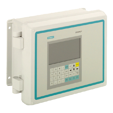
Figure 3-4 KeyPad.........................................................................................................................................29
Figure 3-5 Typical Installation Menu Screen.................................................................................................30
