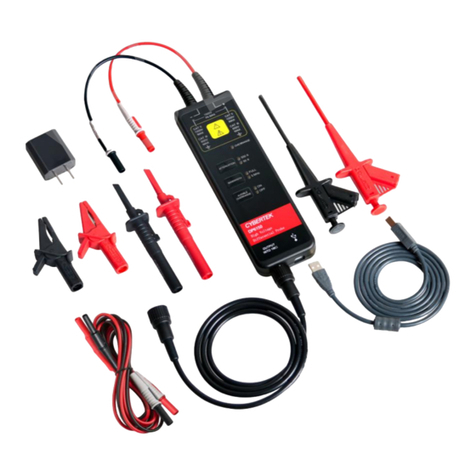
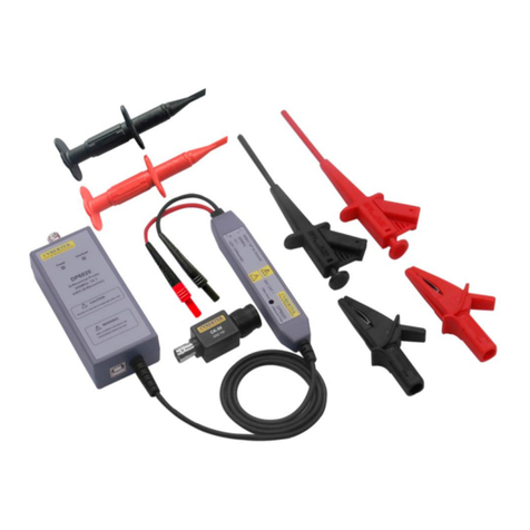
Cybertek DP6065 User manual

CYBERTEK ShenZhen ZhiYong Electronic Co.,Ltd
DP6000 Series
High Voltage Differential Probes
Instruction Manual
DP6065 650Vpk/50MHz
DP6130 1300Vpk/50MHz
DP6130A 1300Vpk/100MHz
DP6560 5600Vpk/50MHz
ShenZhen ZhiYong Electronic Co.,Ltd

CYBERTEK ShenZhen ZhiYong Electronic Co.,Ltd
2
Please read the instructions carefully before use
Safety Notices
1Do not connect or disconnect probes or test leads while they are connected to a voltage
source.
2 Do not operate without covers.
3 Do not operate in wet/damp conditions.
4 Do not operate in an explosive atmosphere.
5 Keep product surfaces clean and dry.
DP6000 Series Brief Description
Name Maximum Input Differential Voltage Bandwidth Attenuation
DP6065 650V 50MHz 10X/100X
DP6130 1300V 50MHz 50X/500X
DP6130A 1300V 100MHz 50X/500X
DP6560 5600V 50MHz 100X/1000X

CYBERTEK ShenZhen ZhiYong Electronic Co.,Ltd
3
Table of Contents
Safety Notices………………………………………. ……….….……….…2
DP6000 Series Brief Description………………………………………..…2
Summary……………………………………………… …………………….4
Application……………………………………… …………………………...4
Products and Accessories…………………… ………………..…….…… 5
Product Standard Accessories…………… ………………… …… …… 10
Warranted Specifications…………… ………… ………… …………..… 11
Typical Mechanical Specifications…… ………… … …… …………..…12
Environment Specifications…………… ……………………… ………...12
Operating the Probe Safely………………………… … ………… …..…13
Reference Notice……………………………… ……… ………………….13
Care and Maintenance………………… ……… …… ……… ………….14
Service Strategy……… ………… ……………… ………… … ………...14
Packing List……… ………… ……………………… …… ………… …...16

CYBERTEK ShenZhen ZhiYong Electronic Co.,Ltd
4
Summary
DP6000 Series High Voltage Differential Probes for measurement of high-voltage differential signal,
to meet the demand for floating measurements。This series has a very high bandwidth to meet the needs of
the majority of the test system;This series has a rich range。Differential measurement voltage range can
meet most of the requirements of the test circuit;Electronic touch buttons, making longer life ;With a 5MHz
bandwidth throttling selection function ,5MHz frequency bandwidth to meet most switching power FETs
switching frequency measurement,And can filter out higher frequency noise and interference;With sound
and light alarm,Manually turn off the sound alarm function is more user-friendly design;Probe is equipped
with a standard BNC output connector ,Can be used with any manufacturer's oscilloscopes (the input
impedance of the oscilloscope setting to 1MΩ ) 。 Probes have good common mode noise rejection
capability;Have a high input impedance and low input capacitance;Accurately measure differential voltage
signals at high speed.
Application
■ Floating voltage measurement
■ Inverter/ transformer design
■ Switching Power Supply Design
■ Solder , plating power supplies
■ Motor drive design
■ Electronic ballast design
■ CRT monitor designe
■ UPS &ATX power supply
■ Power Electronics and Power Drives
■ LED lighting design
CYBERTEK ShenZhen ZhiYong Electronic Co.,Ltd
5
Products and Accessories
■Products Description
1. DP6065

CYBERTEK ShenZhen ZhiYong Electronic Co.,Ltd
6
2. DP6130

CYBERTEK ShenZhen ZhiYong Electronic Co.,Ltd
7
3. DP6130A

CYBERTEK ShenZhen ZhiYong Electronic Co.,Ltd
8
4. DP6560
1)Overrange Indicator
The overrange indicator lights red if the voltage of the input signal exceeds the linear range of the range
setting. When this happens, the signal on the probe output

CYBERTEK ShenZhen ZhiYong Electronic Co.,Ltd
9
2)Attenuation Button and Indicators
Press the button to select between the voltage range (attenuation) settings of the probe. The range is
indicated by two LEDs on the probe 。The Overrage LED lights if the applied voltage exceeds the selected
range. To extinguish the LED, select a higher range.If a higher range is not available, do not attempt to take
the measurement with the probe. does not accurately represent the signal on the probe input.
3)Bandwidth Limit Button and Indicators
Press the button to limit the probe bandwidth to 5 MHz. 5 MHz is close to the switching frequency of
most switching transistors (FETs) in switch mode power supplies (SMPS). The5MHz filter assists in the
characterization and testing of power supplies in switch mode by removing all high frequency content, noise
and harmonics from the measurement. Press the button again to return to the Full position, which selects the
full specified bandwidth of the probe.
4)Audible Overrange On/Off Button and Indicators
Press the button to light the ON LED and enable an audible alarm that indicates when the measured
signal exceeds the selected range. Press the button again to light the OFF LED and disable the audible
feature.
■Probe Standard Accessories
Alligator Clips (CK-261) Alligator Clips (CK-262)
Pincer Clips (CK-281) Hook Clips (CK-284)
Input Leads (CK-326 0.5m)

CYBERTEK ShenZhen ZhiYong Electronic Co.,Ltd
10
Input Leads (CK-368 1m)
Coaxial Output Line(CK-310 1m)
Coaxial Output Line (CK-320 2m)
Adapter(CK-612 12V/1.2A)
Product Standard Accessories
Name DP6065 DP6130 DP6130A DP6560
Alligator Clips (CK-261) CATIII 1000V
CATIV 600V
CATIII 1000V
CATIV 600V
CATIII 1000V
CATIV 600V --
Alligator Clips (CK-262) -- -- -- CATIII 1000V
CATIV 600V
Pincer Clips
(CK-281) CATII 1000V CATII 1000V CATIII 1000V CATII 1000V
Hook Clips (CK-284) CATIII 1000V CATIII 1000V CATIII 1000V CATIII 1000V

CYBERTEK ShenZhen ZhiYong Electronic Co.,Ltd
11
Input Leads (CK-326) -- -- 10A
CATIII 1000V --
Input Leads (CK-368) 10A
CATIII 1000V
10A
CATIII 1000V -- 10A
CATIII 1000V
Coaxial Output Line
(CK-310)
Double-ended BNC Connectors 1m (Product
standard accessories)
Coaxial Output Line
(CK-320)
Double-ended BNC Connectors 2m (non-standard
accessories,purchased separately)
Adapter (CK-612) DC12V/1.2A
Warranted Specifications
Name DP6065 DP6130 DP6130A DP6560
Bandwidth (-3dB) DC to 50MHz DC to 50MHz DC to 100MHz DC to 50MHz
Rise time ≤7ns ≤7ns ≤3.5ns ≤7ns
Accuracy ±2% ±2% ±2% ±2%
Attenuation 10X/100X 50X/500X 50X/500X 100X/1000X
Maximum measurable
differential voltage (DC +
Peak AC)
10X 65V 50X 130V 50X 130V 100X 560V
100X 650V 500X 1300V 500X 1300V 1000X 5600V
Maximum input
voltage-to-earth(Vrms)
450V CATII
600V CATI
600V CATIII
1000V CATII
600V CATIII
1000V CATII
1000V CATIII
2300V CATI
Input
resistance
Each input 2MΩ 4MΩ 4MΩ 20MΩ
Between
inputs 4MΩ 8MΩ 8MΩ 40MΩ
Input
capacitance
Each input <4pF <4pF <4pF <5pF
Between
inputs <2pF <2pF <2pF <2.5pF
CMRR
DC >80dB >80dB >80dB >80dB
100KHz >60dB >60dB >60dB >60dB
1MHz >50dB >50dB >50dB >50dB
Noise(Vrms)
10X <15mV 50X <25mV 50X <25mV 100X <
100mV
100X <50mV 500X <150mV 500X <150mV 1000X <
500mV
Propagation delay 15ns±1ns 15ns±1ns 14ns±1ns 15ns±1ns

CYBERTEK ShenZhen ZhiYong Electronic Co.,Ltd
12
Bandwidth limit filters
(5MHz) ≥-3dB@5MHz ≥-3dB@5MHz ≥-3dB@5MHz ≥-3dB@5MHz
Differential overvoltage
detection level
10X ≥70V 50X ≥140V 50X ≥140V 100X ≥600V
100X ≥700V 500X ≥1400V 500X ≥1400V 1000X ≥6000V
Output termination 1MΩ
Rated power input DC12V/1.2A
Typical Mechanical Specifications
NAME DP6065 DP6130 DP6130A DP6560
Input
Leads
CK-326 Approximately 26cm
CK-368 Approximately 68cm
Output
Leads
CK-310 Approximately 1m
CK-320 Approximately 2m
Alligator Clips CK-261 Approximately 85*40*17mm
Alligator Clips CK-262 Approximately 106*43*16mm
Pincer Clips CK-281 Approximately 152*50*13mm
Hook Clips CK-284 Approximately 121*23*23mm
Probe body dimensions Approximately 195*65*28mm
Weight (probe only) Approximately
176g
Approximately
176g
Approximately
176g Approximately 178g
Environment Specifications
Name DP6065 DP6130 DP6130A DP6560
Operating Temperature 0℃~50℃
Storage Temperature -30℃~70℃
Operating Humidity ≤85%RH
Storage Humidity ≤90%RH

CYBERTEK ShenZhen ZhiYong Electronic Co.,Ltd
13
Operating Altitude 3000m
Storage Altitude 12000m
Operating the Probe Safely
1 Connect the AC adapter to the proper line voltage.Connect t the AC adapter to the probe.
2 Connect the output of the probe to the BNC input of the oscilloscope or other measurement instrument.
The measurement instrument input must be ground-referenced (not floating). The green power LED on
the probe should light.
3 Adjust the vertical offset (or position) of the measurement instrument input.
4 Select the proper range setting. For example, when using the DP6130 probe, to achieve higher resolution
and less noise when measuring signals below 130 Vpk, switch the attenuation to 50X. If the overrange
indicator lights or flashes, the output signal may not be accurate. Use the 500X setting instead.
5 Using the appropriate probe accessories, connect the inputs of the probe to the circuit points to be
measured.
6 Probe body should be kept away from the high-voltage pulse circuit to reduce interference on the probe.
Reference Notice
■Twisting the Input Leads
Twisting the input leads helps to cancel noise that is induced into the input leads, and to improve the high
frequency response of the inputs. For the best response possible, do not use the extension leads.
■Extension Leads
The extension leads allow you to reach widely spaced connection points. Connect the extension leads to
the input leads using the adapters provided. Be sure to use both extension leads so that the input leads
are the same length. The extension leads, however, do affect the high-frequency performance of the probe.
With longer lead length, differential noise induced into the input leads is greater. Also, because of the

CYBERTEK ShenZhen ZhiYong Electronic Co.,Ltd
14
added inductance of he leads, voltage measurements at frequencies above approximately 10 MHz may
not be as precise. The following figure shows the effect on HF transient response with (left waveform) and
without (right waveform). The extension leads do not affect the performance of the probe when bandwidth
is set to 5 MHz.
HF transient response with (left) and without (right) extension leads
■Probe Loading
When you touch your probe tip to a circuit element, you are introducing a new resistance, capacitance,
and inductance into the circuit. Frequency and impedance of the source determine how much the probe
loads the circuit that you are measuring. As the frequency of the source starts to increase beyond 1 kHz,
the input impedance of the probe begins to decrease. The lower the impedance of the probe relative to
that of the source, the more the probe loads the circuit under test. The probe has virtually no loading
effect on sources with relatively low impedance and low frequency.
Care and Maintenance
1 Keep the probe clean and dry.
2 To prevent damage to the probe, do not expose it to sprays, liquids, or solvents.
3 Avoid getting moisture inside the probe when cleaning the exterior.
4 DON’T pull the input leads and output leads violently.
Service Strategy
You can return the current probe to Shenzhen Zhiyong Electronic Co.,Ld for Service.
In the China, call (0755) 86628000 for further details and the location of your nearest Shenzhen Zhiyong
Electronic Co.,Ld service center.
Outside the China, call your nearest Zhiyong sales office and ask them how to contact the nearest
Zhiyong service center.

CYBERTEK ShenZhen ZhiYong Electronic Co.,Ltd
15
1 Write the following information on a tag and attach it to the current probe.
•Name and address of the owner
•Current probe model number
•Description of service required or failure indications
2 Retain all accessories.
3 Return the current probe in its original shipping materials or pack the power supply in foam or other
shock- absorbing material and place it in a strong shipping container. If the original shipping
materials are not available, place 3 to 4 inches of shock- absorbing material around the instrument
and place it in a box that does not allow movement during shipping.
4 Seal the shipping container securely.
5 Mark the shipping container as FRAGILE. In all correspondence, refer to the current probe by
model number and full serial number.

CYBERTEK ShenZhen ZhiYong Electronic Co.,Ltd
16
Packing List
Packing List
Name DP6065 DP6130 DP6130A DP6560
Voltage probe body 1 1 1 1
DC12V/1.2A(CK-612) 1 1 1 1
Alligator Clips (CK-261) 1 1 1 --
Alligator Clips (CK-262) -- -- -- 1
Pincer Clips (CK-281) 1 1 1 1
Hook Clips (CK-284) 1 1 1 1
Input Leads(CK-326) -- -- 1 --
Input Leads(CK-368) 1 1 -- 1
Output Leads(CK-310) 1 1 1 1
Tool bag 1 1 1 1
Instruction manual 1 1 1 1
Warranty card 1 1 1 1
Test Report 1 1 1 1
CYBERTEK
ShenZhen ZhiYong Electronic Co.,Ltd
Addr:
Room A1702, Building 4, TianAn Cyber Park, HuangGe North Road,LongGang District,
ShenZhen City,China
Tel: 400 852 0005
0755-8662 8000
0755-8662 8001
Fax: 0755-8662 0008
Url: http://www.cybertek.cn
This manual suits for next models
3
Table of contents
Other Cybertek Measuring Instrument manuals

Cybertek
Cybertek HCP8000 Series User manual

Cybertek
Cybertek CP8000 Series User manual

Cybertek
Cybertek OP6031 User manual

Cybertek
Cybertek EM5030 User manual

Cybertek
Cybertek CPL8100A User manual

Cybertek
Cybertek DP6000 Series User manual

Cybertek
Cybertek CTB20B User manual

Cybertek
Cybertek DP6020 User manual

Cybertek
Cybertek DP6000 Series User manual

Cybertek
Cybertek CPL2000 User manual