GMG VM26-J User manual

Global Machinery Group, Inc.
Operator’s Manual
Specifications . . . . . . . . . . . . . . . . . . . . . . . . . . . . . . . . . . . . . . . . . . . . inside cover
Introduction . . . . . . . . . . . . . . . . . . . . . . . . . . . . . . . . . . . . . . . . . . . . . . . . . . . . . . . 1
Safety. . . . . . . . . . . . . . . . . . . . . . . . . . . . . . . . . . . . . . . . . . . . . . . . . . . . . . . . . . . . . . 2
California Proposition 65 Warning . . . . . . . . . . . . . . . . . . . . . . . . . . . . . . . . . . . . . 2
Safety Alert Symbols . . . . . . . . . . . . . . . . . . . . . . . . . . . . . . . . . . . . . . . . . . . . . . . . . . 2
Electrocution Hazard. . . . . . . . . . . . . . . . . . . . . . . . . . . . . . . . . . . . . . . . . . . . . . . . . . 3
Tip-over Hazards. . . . . . . . . . . . . . . . . . . . . . . . . . . . . . . . . . . . . . . . . . . . . . . . . . . . . . 4
Fall Hazards. . . . . . . . . . . . . . . . . . . . . . . . . . . . . . . . . . . . . . . . . . . . . . . . . . . . . . . . . . . 5
Collision Hazards . . . . . . . . . . . . . . . . . . . . . . . . . . . . . . . . . . . . . . . . . . . . . . . . . . . . . 5
Additional Safety Hazards . . . . . . . . . . . . . . . . . . . . . . . . . . . . . . . . . . . . . . . . . . . . . 6
Battery Safety. . . . . . . . . . . . . . . . . . . . . . . . . . . . . . . . . . . . . . . . . . . . . . . . . . . . . . . . . 6
Controls & Components . . . . . . . . . . . . . . . . . . . . . . . . . . . . . . . . . . . . . . . . . . . . . 7
Component Locations . . . . . . . . . . . . . . . . . . . . . . . . . . . . . . . . . . . . . . . . . . . . . . . . 7
Platform Controls . . . . . . . . . . . . . . . . . . . . . . . . . . . . . . . . . . . . . . . . . . . . . . . . . . . . . 8
Lower Controls . . . . . . . . . . . . . . . . . . . . . . . . . . . . . . . . . . . . . . . . . . . . . . . . . . . . . . . 9
Workplace Inspection . . . . . . . . . . . . . . . . . . . . . . . . . . . . . . . . . . . . . . . . . . . . . . 10
Operating Instructions & Function Tests. . . . . . . . . . . . . . . . . . . . . . . . . . . . . 11
Prestart . . . . . . . . . . . . . . . . . . . . . . . . . . . . . . . . . . . . . . . . . . . . . . . . . . . . . . . . . . . . . . 11
Functions Test . . . . . . . . . . . . . . . . . . . . . . . . . . . . . . . . . . . . . . . . . . . . . . . . . . . . . . . 11
Operating Instructions . . . . . . . . . . . . . . . . . . . . . . . . . . . . . . . . . . . . . . . . . . . . . . . 16
Shutdown Procedure . . . . . . . . . . . . . . . . . . . . . . . . . . . . . . . . . . . . . . . . . . . . . . . 19
Battery Charging. . . . . . . . . . . . . . . . . . . . . . . . . . . . . . . . . . . . . . . . . . . . . . . . . . . . . 20
Maintenance . . . . . . . . . . . . . . . . . . . . . . . . . . . . . . . . . . . . . . . . . . . . . . . . . . . . . . 21
Routine Maintenance . . . . . . . . . . . . . . . . . . . . . . . . . . . . . . . . . . . . . . . . . . . . . . . . 22
Frequent and Annual Maintenance . . . . . . . . . . . . . . . . . . . . . . . . . . . . . . . . . . . 22
Lubrication . . . . . . . . . . . . . . . . . . . . . . . . . . . . . . . . . . . . . . . . . . . . . . . . . . . . . . . . . . 23
Pre-Start Inspection Checklist . . . . . . . . . . . . . . . . . . . . . . . . . . . . . . . . . . . . . . . . 24
Frequent Inspection Checklist . . . . . . . . . . . . . . . . . . . . . . . . . . . . . . . . . . . . . . . . 25
Troubleshooting . . . . . . . . . . . . . . . . . . . . . . . . . . . . . . . . . . . . . . . . . . . . . . . . . . 26
Transport and Lifting Instructions . . . . . . . . . . . . . . . . . . . . . . . . . . . . . . . . . . 27
Lifting Instructions . . . . . . . . . . . . . . . . . . . . . . . . . . . . . . . . . . . . . . . . . . . . . . . . . . . 27
Loading . . . . . . . . . . . . . . . . . . . . . . . . . . . . . . . . . . . . . . . . . . . . . . . . . . . . . . . . . . . . . 27
VM26-J
Serial # 213301001 - Up
1OPVM26EN
April 2018

—Specifications—
Meets applicable requirements of ANSI A92.5-2006.
*Working Heigh adds 6 feet (2 m) to platform height.
**Weight may increase with certain options.
C
A
F
B
D
E
Power
Power source 24v, 240Ah
Weight
ANSI 6,405 lbs 2,905 kg
CE 6,405 lbs 2,905 kg
MODEL VM26-J
Measurements US Metric
Working height maximum 32.5’ 10 m
Platform height maximum
A
26.5’ 8 m
Outreach maximum 10.3’ 3.15 m
Platform length 33.5” .85 m
Platform width 35.8” .91 m
Toeboard height 6.7” 0.17 m
Height - stowed
B
78” 1.99 m
C
Length stowed 108.6” 2.76 m
Width
D
39” .99 m
Wheelbase
E
47” 1.2 m
F
Ground clearance - center
-- pothole bars ground c
3”
1”
7.5 cm
2.5 cm
Productivity
Maximum platform occupancy 2
Lifting capacity 440 lbs 200 kg
Drive height Full Height
Drive speed - stowed 2.8 mph 4.5 km/h
Drive speed - raised 0.3 mph 0.5 km/h
Gradeability - stowed 40%
Turning radius - inside 0
Jib swing -60°/ +60°
Vertical tilt maximum 3°
Controls Fully Proportional
Drive Direct Electric
Tires - Solid, Non-marking 16” x 5” 40.6 x 12.7 cm
A
B
C
D
E
F

1OPVM26EN – April 2018 Page 1
VM26-J Introduction
Introduction
This Operator’s Manual has been designed to provide you, the owner, user or operator, with the instructions and operating procedures
essential to properly and safely operate your GMG Aerial Work Platform for positioning personnel, along with their necessary tools
and materials, to overhead work locations.
The Operator’s Manual must be read and understood prior to operating your GMG Aerial Work
Platform. The user/operator should not accept operating responsibility until he/she has read and
understands the operator’s manual as well as having operated the GMG Aerial Work Platform under
supervision of an authorized, trained and qualified operator.
It is essential that the operator of the aerial work platform is not alone on the workplace during
operation.
Modifications of this machine from the original design and specifications without written permission
from GMG are strictly forbidden. A modification may compromise the safety of the machine, subjecting
operator(s) to serious injury or death.
Your GMG Aerial Work Platform has been designed, built, and tested to provide safe,
dependable service. Only authorized, trained and qualified personnel shall be allowed to
operate or service the machine.
GMG, as manufacturer, has no direct control over machine application and operation. Proper
safety practices are the responsibility of the owner, user and operator.
If there is a question on application and/or operation contact:
Global Machinery Group
Global Machinery Group, Inc.
3428 Bullock Lane
San Luis Obispo, CA 93401 USA
Phone: +1.805.303.2066
Toll Free (USA/Canada): 800.303.0499
www.goGMG.com
Global Machinery Group, Inc.

Page 2 1OPVM26EN – April 2018
VM26-J Safety
Safety
DO NOT operate this machine until you have read and understood this manual, have performed the Workplace Inspection,
Pre-Start Inspection and Routine Maintenance, and have completed all the test operations detailed in the Operating
Instructions section.
Failure to read, understand and follow all safety rules, warnings, and instructions could result in serious injury or death. For your
safety and the safety of those around you, you must operate your machine as instructed in this manual.
GMG designs aerial work platforms to safely and reliably position personnel, along with their necessary tools and materials, at
overhead work locations. The owner/user/operator of the machine should not accept responsibility for the operation of the machine
unless properly trained.
ANSI and other applicable standards identify requirements of all parties who may be involved with self-propelled elevating work
platforms. The ANSI/SIA A92.5-2006 Manual of Responsibilities is considered a part of this machine and can be found in the manual
compartment, located at the platform control station. To ensure safe use of machine, inspections and training specified in ANSI/SIA
A92.5-2006 must be performed at designated intervals as prescribed.
California Proposition 65 Warning
This product contains chemicals known to the State of California to cause cancer and/or birth
defects or other reproductive harm.
Safety Alert Symbols
GMG manuals and decals use symbols and colors to help you recognize important safety, operation and maintenance information.
RED – Indicates an imminently hazardous situation which, if not avoided, will result in death or serious
injury.
ORANGE – Indicates a potentially hazardous situation which, if not avoided, could result in death or
serious injury.
YELLOW with alert symbol – Indicates a potentially hazardous situation which, if not avoided, may
result in minor or moderate injury.
YELLOW without alert symbol – Indicates a potentially hazardous situation which, if not avoided, may
result in property damage.
GREEN – Indicates operation or maintenance information.

1OPVM26EN – April 2018 Page 3
VM26-J Safety
Fall Protection
Operators must comply with employer, job site and governmental rules regarding the use of
personal protective equipment.
ALL OPERATORS MUST USE PERSONAL FALL PROTECTION EQUIPMENT (PFPE)
WHEN OPERATING THIS MACHINE.
All PFPE must comply with applicable governmental regulations, and must be inspected and
used in accordance with the PFPE manufacturer’s instructions.
Fall restraint must be properly attached to a designated anchorage point when driving or
operating the machine. Attach only one fall restraint to each anchorage point.
Electrocution Hazard
ELECTROCUTION HAZARD! THIS MACHINE IS NOT INSULATED!
DEATH OR SERIOUS INJURY will result from contact with or inadequate clearance from any electrically
charged conductor.
You must maintain a CLEARANCE OF AT LEAST 10 FEET (3.05 m) between any part of the machine, or its
load, and any electrical line or apparatus carrying over 300 Volts up to 50,000 Volts. One foot (30.5 cm)
additional clearance is required for every additional 30,000 Volts.
Observe Minimum Safe Approach Distance.
This machine is not electrically insulated and will not provide protection from contact with or
proximity to electrical current.
Maintain safe distances from electrical power lines and apparatus in accordance with
applicable government regulations and the following chart:
Allow for platform movement, electrical line sway or sag and beware of strong or gusty winds.
Keep away from the machine if it contacts energized power lines. Personnel on the ground or
in the platform must not touch or operate the machine until energized power lines are shut off.
Do not use the machine as a ground for welding.
13354
13342
13343
Minimum Save Approach Distance
Voltage Minimum Safe Approach Distance
Phase to Phase Feet Meters
0 to 300 Volts Avoid Contact
Over 300V to 50kv 10 3.1
Over 50KV to 200KV 15 4.6
Over 200KV to 350KV 20 6.1
Over 350KV to 500KV 25 7.6
Over 500KV to 750KV 35 10.7
Over 750KV to 1000KV 45 13.7

Page 4 1OPVM26EN – April 2018
VM26-J Safety
Tip-over Hazards
DO NOT exceed the maximum platform capacity. The weight of options and accessories will
reduce the rated platform capacity and must be factored into the total platform load. Refer to
the decals on the options.
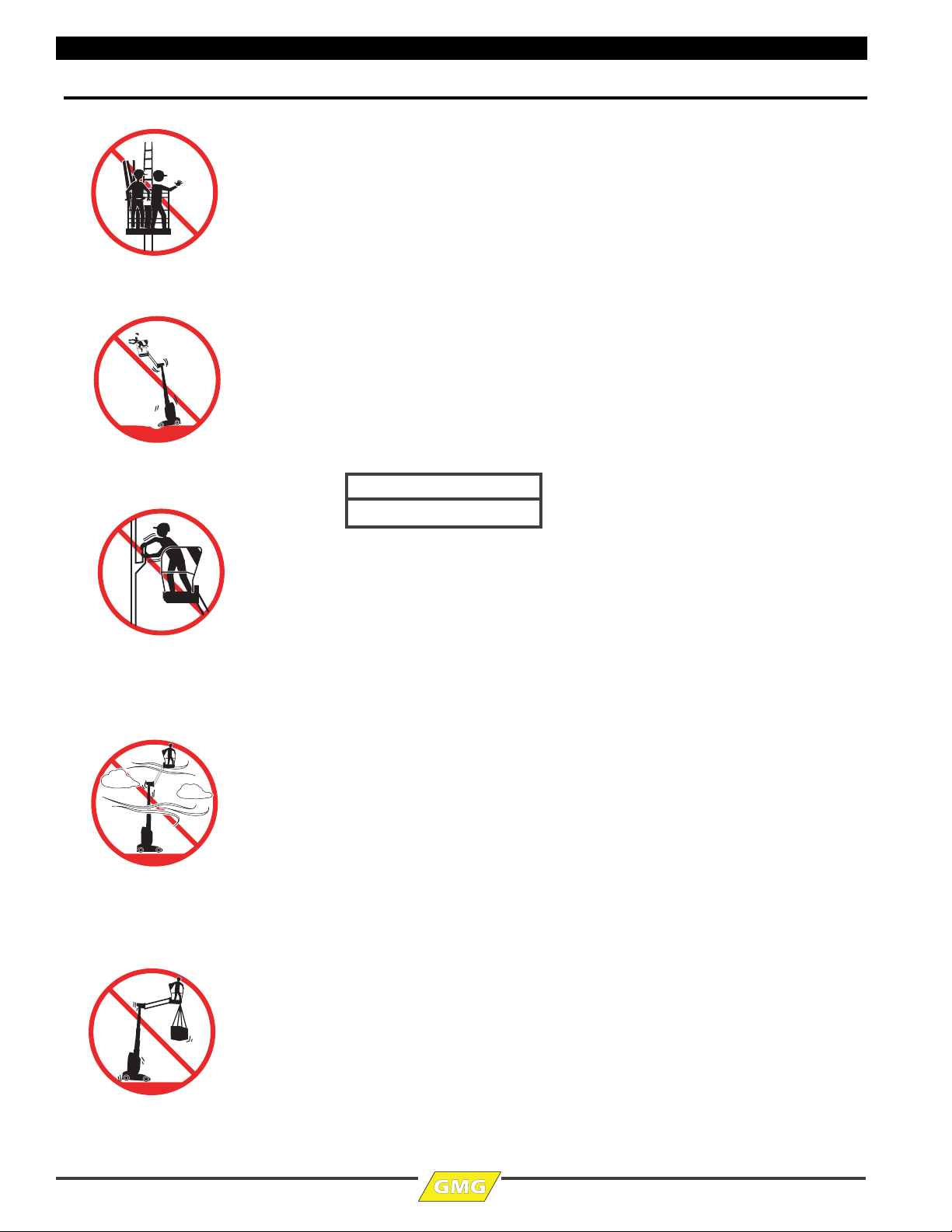
DO NOT elevate the platform when the machine is on a surface that is soft and / or on a slope.
DO NOT depend on the tilt alarm as a level indicator. STOP if the tilt alarm sounds and the
red light illuminates when the platform is raised. Use extreme caution to lower the platform.
Move the machine to a rm, level surface.
Driving: DO NOT drive the machine on a slope that exceeds the maximum uphill or downhill
slope rating. Slope rating applies to machines in the stowed position.
Driving in stowed position: use extreme care and reduce speed when driving across uneven
terrain, debris, unstable or slippery surfaces, and near holes or drop-offs.
Driving with the platform elevated: DO NOT drive on or near uneven terrain, unstable
surfaces, curbs, drop-offs or other hazardous conditions.
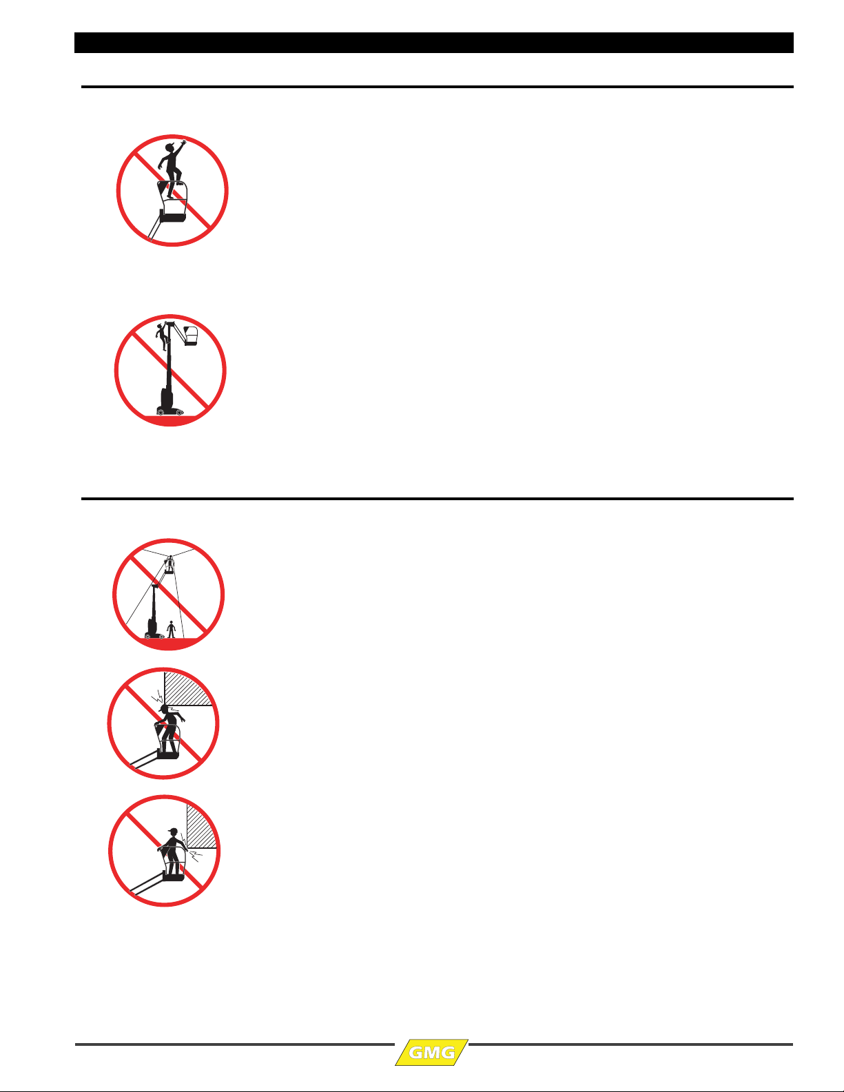
DO NOT push or pull toward any object outside the platform. DO NOT push the machine or
other objects with the platform. DO NOT contact adjacent structures with the platform.
DO NOT tie the platform to adjacent structures.
DO NOT use the platform controls to free a platform that is caught, snagged or otherwise
prevented from normal motion by an adjacent structure.
For outdoor rated machines, DO NOT elevate the platform when wind speeds are in excess of
28 m.p.h. (12.5 m/s). If wind speeds exceed 28 m.p.h. (12.5 m/s) when the platform is elevated,
carefully lower the platform and discontinue operation.
DO NOT increase the surface area of the platform (i.e. cover the rails with tarp or plywood).
Increased surface area exposed to the wind will decrease machine stability.
DO NOT attach overhanging loads or use the machine as a crane. DO NOT place loads outside
the platform perimeter.
NEVER transport tools and materials unless they are firmly secured. Secure all tools and loose
materials.
NEVER alter or disable any machine components.
NEVER replace any part of the machine with items of different weight or specification.
NEVER modify or alter the work platform without written permission from GMG.
NEVER place ladders or scaffolds in the platform or against any part of the machine.
NEVER use the machine on a moving or mobile surface or vehicle.
Ensure that all tires are in good condition and lug nuts are properly torqued.
DO NOT operate the machine with the chassis trays open.
DO NOT alter or disable the limit switches or machine components that in any way affect
safety and stability.
DO NOT replace items critical to machine stability with items of different weight or
specification. DO NOT modify or alter this machine without prior written permission from
the manufacturer.
DO NOT use batteries that weigh less than the original equipment. Each battery must weigh
55 lbs/25 kg. The batteries must weigh a minimum of 110 lbs/50 kg.
DO NOT OVERLOAD
DO NOT DRIVE ON IRREGULAR OR
UNSTABLE SURFACE
DO NOT PUSH OR PULL OBJECTS
OUTSIDE PLATFORM
DO NOT ELEVATE IN WINDY
CONDITIONS
DO NOT USE AS CRANE
13344
13345
13346
13347
13348
Maximum Allowable Side Force
50 lbs (222 N) per person

1OPVM26EN – April 2018 Page 5
VM26-J Safety
Fall Hazards
DO NOT sit, stand or climb on the platform guard rails. Maintain a firm footing on the
platform floor at all times.
DO NOT exit the platform when elevated
Keep the platform floor clear of debris.
DO NOT fasten a fall restraint lanyard to an adjacent structure.
Ensure that all gates are properly closed and secured before operating the machine.
Operators must comply with employer and job site rules and governmental regulations
regarding the use of personal protective equipment.
Collision Hazards
Check for equipment, materials or other obstructions before moving.
Check for overhead obstructions before moving.
Check for crushing hazards when holding the platform rail before moving.
Be aware of limited sight distance and blind spots when driving or operating.
Be aware of extended platform position(s) when moving the machine.
Reduce travel speed when moving the machine on slopes, when near personnel and obstacles,
or when surface conditions are wet, slippery or otherwise limiting.
DO NOT operate in the path of any crane unless the controls of the crane have been locked out
and/or precautions have been taken to prevent any possible collision.
Stunt driving and horseplay are PROHIBITTED.
Watch for personnel and obstructions below the platform when lowering the platform.
Keep hands and limbs out of lift assembly.
Use common sense and planning when operating the machine with the controller from the
ground. Maintain safe distances between the operator, the machine and fixed objects.
DO NOT EXIT PLATFORM WHEN
ELEVATED
DO NOT CLIMB ON RAILS
13349
13350
13351
13352
13353

Page 6 1OPVM26EN – April 2018
VM26-J Safety
Additional Safety Hazards
Explosion and Fire Hazards
DO NOT operate the machine in hazardous locations or locations where potentially
flammable or explosive gases or particles may be present.
Damaged Machine Hazards
Conduct a thorough prestart inspection of the machine and test all functions before each work
shift to check for damage, malfunction and unauthorized modification. Tag and remove a
damaged, malfunctioning or modified machine from service. DO NOT use a damaged,
malfunctioning or modified machine.
Routine maintenance must be performed by the operator before each work shift. Scheduled
maintenance must be performed by a qualified service technician at scheduled intervals. Tag
and remove from service any machine that has not had scheduled preventative maintenance
performed.
Check that all safety and instructional decals are in place and undamaged.
Check that the operator’s, safety and responsibilities manuals are present in the storage
container located in the platform. All manuals must be complete, undamaged and readable.
Bodily Injury Hazards
DO NOT operate the machine when there is a hydraulic fluid or air leak. Hydraulic fluid or air
under pressure can penetrate and/or burn skin.
All compartments must remain closed and secure during machine operation. Improper
contact with components under any cover will cause serious injury. Only trained maintenance
personnel should access compartments. The operator should only access a compartment when
performing prestart inspection.
Weld Line to Platform Safety (if equipped)
Read, understand and follow all warnings and instructions provided with the welding power
unit.
Do not connect weld leads or cables unless the welding power unit is turned off at the platform
controls.
DO NOT operate unless the weld cables are properly connected.
DO NOT connect the ground lead to the platform.
Battery Safety
Burn Hazards
Batteries contain acid. Always wear protective clothing and eye wear when working with
batteries.
Avoid spilling or contacting battery acid. Neutralize battery acid spills with baking soda and
water.
Explosion Hazard
Keep sparks, flame and lighted tobacco away from batteries. Batteries emit explosive gas.
Leave the battery tray open while charging to avoid gas buildup.
Electrocution Hazard
Avoid contact with electrical terminals.

1OPVM26EN – April 2018 Page 7
VM26-J Controls & Components
Controls & Components
Component Locations
13355
Guardrails
Entry Gate
Entry Gate
Lift Mast
Rotating
Turret
Tie-Down/
Lift Points
Tie-Down/
Lift Points
Platform Controls
Platform
Controls
Manuals
Case
Foot Interlock
Switch
Platform
Chassis
Lower
Control
Station
Battery
Charger
(beneath
cover)

Page 8 1OPVM26EN – April 2018
VM26-J Controls & Components
Platform Controls
ALWAYS be aware of the machine’s position and of your surroundings
before activating any control function.
13356
1 3 4 5 62 7
8
910
Platform Controls
Foot Interlock
Switch
CONTROL DESCRIPTION
-- Foot Interlock Switch The Foot Interlock Switch must be depressed to enable machine functions.
1 Emergency Stop Switch Press the EMERGENCY STOP switch at any time to stop all machine functions.
Pull to reset.
2 Horn Button Press to sound warning horn.
3 Lift Function Select Press this switch to enable the Lift function. Depress the Foot Interlock Switch, then use the
Right Control Paddle to lift and lower the mast.
4 Rotate Function Select Press this switch to enable the Rotate function. Depress the Foot Interlock Switch, then use the
Left Control Paddle to rotate the turret.
5 Jib Function Select Press this switch to enable the Jib function. Depress the Foot Interlock Switch, then use the
Right Control Paddle to lift and lower the jib.
6 Drive Function Select Press this switch to enable the Drive function. Depress the Foot Interlock Switch, then use the
Right Control Paddle to control driving forward and backward. Use the Left Control Paddle to
control steering.
7 Drive Speed Select Position the switch DOWN toward the turtle to select Low Speed Drive.
Position the switch UP toward the rabbit to select High Speed Drive.
8 Power On Indicator Light ON indicates machine is ready for use. Light OFF may indicate a depressed Emergency
Stop Button, Key Switch in the OFF position, or discharged batteries.
9 Right Control Paddle Use this paddle to control Drive, Jib and Lift functions.
10 Left Control Paddle Use this paddle to control Steer and Rotate functions.

1OPVM26EN – April 2018 Page 9
VM26-J Controls & Components
Lower Controls
ALWAYS be aware of the machine’s position and of your surroundings
before activating any control function.
CONTROL DESCRIPTION
1 Emergency Stop Switch Press the EMERGENCY STOP switch at any time to stop all machine functions.
Pull to reset.
2 Rotate Function Press and hold this switch to enable the Rotate function, then use the Base Control Paddle to
rotate the turret.
3 Hour Meter Indicates total elapsed time of machine operation.
4 Brake Release Switch Press and hold this to release brakes. Release after use.
DO NOT operate the brake release if the machine is elevated or is on a sloped surface, or if
there is an operator in the platform.
5 Power On Indicator Light ON indicates machine is ready for use. Light OFF may indicate a depressed Emergency
Stop Button, Key Switch in the OFF position, or discharged batteries.
6 Base Control Paddle Use this paddle to control The Rotate, Jib and Lift functions from the Lower Controls Station.
7 Jib Function Press and hold this switch to enable the Jib function, then use the Base Control Paddle to lift and
lower the jib.
8 Key Switch PLATFORM (red) Select to operate from the platform control panel.
BASE (green) Select to operate from the base control panel.
OFF (yellow) Select to stop operation from either control panel.
9 Fault Indicator Indicates that an error has occurred in the operating system by flashing error codes.
10 Lift Function Press and hold this switch to enable the Lift function, then use the Base Control Paddle to lift
and lower the mast.
13357
1
2
3
4
6
5
7
8
9
10
Lower
Controls

Page 10 1OPVM26EN – April 2018
VM26-J Workplace Inspection
Workplace Inspection
DO NOT operate this machine until you have read and understood this manual, have performed the Workplace Inspection,
Pre-Start Inspection and Routine Maintenance, and have completed all the test operations detailed in the Operating
Instructions section.
Inspect the workplace and determine whether the workplace is suitable for safe machine operation. Do this before moving the
machine to the workplace.
Be sure the lift is the correct machine for the job.
Be aware of workplace conditions, and continue to watch for hazards while operating the machine.
Workplace Inspection
Before operating the machine, check the workplace for all possible hazards, including but not
limited to:
• drop-offs or holes, including those concealed by water, ice, mud, etc.
• sloped, unstable or slippery surfaces
• bumps, surface obstructions and debris
• overhead obstructions and electrical conductors
• other objects or equipment
• hazardous locations and atmospheres
• inadequate surface and support to withstand all load forces imposed by the machine
• wind and weather conditions
• the presence of unauthorized personnel
• other possible unsafe conditions

1OPVM26EN – April 2018 Page 11
VM26-J Operating Instructions & Function Tests
Operating Instructions & Function Tests
DO NOT operate this machine until you have read and understood this manual, have performed the Workplace Inspection,
Prestart Inspection and Routine Maintenance, and have completed all the test operations detailed in the Operating Instructions
section.
This section provides instructions and tests for each function of machine operation. Follow all safety rules and instructions. The
operator must conduct inspections and a Functions Test of the machine before each work shift to check that all machine systems are
working properly.
Test the machine on a firm level surface with no debris, drop-offs, potholes or overhead obstructions. Perform each step outlined in
this section.
This machine shall only be operated by trained and authorized personnel. If multiple operators use this machine, all must be trained,
qualified and authorized to use it. New operators must perform a Pre-Start Inspection and Functions Test prior to operating the
machine.
Operators must comply with all employer and job site rules and governmental regulations regarding the use of personal protective
equipment.
DO NOT use a machine that is malfunctioning. If any function does not perform as described, tag the machine and remove for repair
by a qualified service technician. After repairs are completed, a Pre-Start Inspection and Functions Test must be performed before
using the machine.
Refer to Platform Controls on page 8 and Lower Controls on page 9 when performing the following functions tests and operating
instructions.
Prestart
•PerformPrestart Inspection (see page 24).
• Check Emergency Stop Switch at the platform controls – pull to reset.
• Check Main Power/Lower Emergency Stop Switch at the lower controls – pull to reset.
Functions Test
1 Select a test area that is firm, level and free of obstruction.
2 Be sure the battery pack is connected.
At the Ground Controls
3 Set the red Emergency Stop button to the on position by pulling it out at both the
ground and platform controls.
4 Turn the Key Switch to ground control.
13358

Page 12 1OPVM26EN – April 2018
VM26-J Operating Instructions & Function Tests
Test Emergency Stop
5 Push in the ground red Emergency Stop button to the OFF position.
• Result: No functions should operate.
6 Pull the red Emergency Stop button out to the ON position.
• Result: The Power On Indicator light should illuminate.
Test Lift Functions
Check the area above and around the machine for obstructions and electrical power lines before
operating the machine.
7 At the Lower Controls station, turn the Key Switch to off or platform position.
8 At the Lower Controls station, push and hold the Lift Function enable switch, then
push the Base Control Paddle up and down.
• Result: No function should operate.
9 Turn the Key Switch to ground control position.
10 At the Lower Controls station, push and hold the Lift Function enable switch, then
push the Base Control Paddle up.
• Result: The platform should raise.
11 Push and hold the Lift Function enable switch, then push the Base Control Paddle
down.
• Result: The platform should lower. The descent alarm should sound while the
platform is lowering.
Test Rotate Functions
Check the area above and around the machine for obstructions and electrical power lines before
operating the machine.
12 At the Lower Controls station, turn the Key Switch to off or platform position.
13 At the Lower Controls station, push and hold the Rotate Function enable switch, then
push the Base Control Paddle up and down.
• Result: No function should operate.
14 Turn the Key Switch to ground control position.
15 At the Lower Controls station, push and hold the Rotate Function enable switch, then
push the Base Control Paddle up.
• Result: The turret should rotate to the right.
16 Push and hold the Rotate Function enable switch, then push the Base Control Paddle
down.
• Result: The turret should rotate to the Left.

1OPVM26EN – April 2018 Page 13
VM26-J Operating Instructions & Function Tests
Test Jib Functions
Check the area above and around the machine for obstructions and electrical power lines before
operating the machine.
17 At the Lower Controls station, turn the Key Switch to off or platform position.
18 At the Lower Controls station, push and hold the Jib Function enable switch, then
push the Base Control Paddle up and down.
• Result: No function should operate.
19 Turn the Key Switch to ground control position.
20 At the Lower Controls station, push and hold the Jib Function enable switch, then
push the Base Control Paddle up.
• Result: The jib and platform should rise.
21 Push and hold the Jib Function enable switch, then push the Base Control Paddle
down.
• Result: The jib and platform should lower.
Test the Emergency Lowering
22 Activate the Lift function and raise the mast approximately 2 ft / 60 cm.
23 Activate the Emergency Lowering Valve on the side of the hydraulic pump.
• Result: The platform should lower. The descent alarm will not sound.
At the Platform Controls
24 Turn the Key Switch to platform control.
Test Emergency Stop
25 Push in the platform red Emergency Stop button to the OFF position.
• Result: No functions should operate.
26 Pull the red Emergency Stop button out to the ON position.
• Result: The Power On Indicator light should illuminate.
Test the Horn
27 Push the horn button.
• Result: The horn should sound.

Page 14 1OPVM26EN – April 2018
VM26-J Operating Instructions & Function Tests
Test Foot Interlock Switch and Lift Functions
Check the area above and around the machine for obstructions and electrical power lines before
operating the machine.
28 Press the Lift Function Select switch. The light above it should illuminate.
29 DO NOT press the Foot Interlock Switch on the platform floor.
30 Slowly move the Right Control Paddle forward, the rearward.
• Result: No functions should operate.
31 Press and hold the Foot Interlock Switch on the platform floor.
32 Slowly move the Right Control Paddle forward.
• Result: The mast should rise.
33 Release the Foot Interlock Switch.
• Result: The mast should stop rising.
34 Press and hold the Foot Interlock Switch on the platform floor. Slowly push the Right
Control Paddle rearward.
• Result: The platform should lower. The descent alarm should sound while the
platform is lowering.
Test the Rotation Function
35 Press the Rotate Function Select switch. The light above it should illuminate.
36 Press and hold the Foot Interlock Switch on the platform floor.
37 Push the Left Control Paddle to the left.
• Result: The turret should rotate to the left.
38 Push the Left Control Paddle to the right.
• Result: The turret should rotate to the right
Test the Jib Function
39 Press the Jib Function Select switch. The light above it should illuminate.
40 Press and hold the Foot Interlock Switch on the platform floor.
41 Push the Right Control Paddle forward.
• Result: The jib and platform should rise.
42 Push the Right Control Paddle rearward.
• Result: The jib and platform should descend.

1OPVM26EN – April 2018 Page 15
VM26-J Operating Instructions & Function Tests
Test the Steering Function
Depending on how the turret is rotated, both Drive and Steer functions may respond unexpectedly.
Note the position of the arrows on the Drive Function Select icon before moving the Control Paddles.
When performing the steer and drive function tests, rotate the turret so that the steering end
of the machine is forward.
43 Press the Drive Function Select switch. The light above it should illuminate.
44 Press and hold the Foot Interlock Switch on the platform floor.
45 Push the Left Control Paddle to the left.
• Result: The steer wheels should turn in the direction that the green left arrow points
on the control panel.
46 Push the Left Control Paddle to the right.
• Result: The steer wheels should turn in the direction that the yellow right arrow points
on the control panel.
Test Drive and Braking
47 Press and hold the Foot Interlock Switch on the platform floor.
48 Slowly move the Right Control Paddle in the direction indicated by the yellow up
arrow on the control panel until the machine begins to move, then return the handle
to the center position.
• Result: The machine should move in the direction that the yellow up arrow points on
the control panel, then come to an abrupt stop.
49 Press and hold the Foot Interlock Switch on the platform floor.
50 Slowly move the Right Control Paddle in the direction indicated by the green down
arrow on the control panel until the machine begins to move, then return the handle
to the center position.
• Result: The machine should move in the direction that the green down arrow points
on the control panel, then come to an abrupt stop.
Note: The brakes must be able to hold the machine on any slope it is able to
climb.
Test Limited Drive Speed
51 Press the Lift function select button.
52 Press and hold the Foot Interlock Switch on the platform floor. Raise the platform
approximately 6 ft /2 m from the ground.
53 Press the Drive function select button.
54 Press and hold the Foot Interlock Switch on the platform floor.
55 Slowly move the Right Control Paddle to the full drive position.
• Result: The maximum achievable drive speed with the platform raised should not
exceed .63 ft per second / 20 cm/s.
• If the drive speed with the platform raised exceeds .63 ft per second / 20 cm/s,
immediately tag and remove the machine from service.

Page 16 1OPVM26EN – April 2018
VM26-J Operating Instructions & Function Tests
Operating Instructions
Check the area above and around the machine for obstructions and electrical power lines before
operating the machine.
Emergency Stop
• Push in the red
Emergency Stop
button to the off
position at the
ground controls or
the platform controls
to stop all machine
functions.
•Ifanyfunction
operates when either
red Emergency Stop
button is pushed in,
repair the
Emergency Stop
function before
using the machine.
Emergency Lowering
If the control system fails while the platform is elevated, use the Emergency Lowering Valve to safely
lower the platform.
DO NOT climb down the mast or exit the platform.
The Emergency Lowering Valve is used to lower the platform in case of power failure.
• Activate the Emergency Lowering Valve on the side of the hydraulic pump to
lower the platform.
Operation from Ground
Check the area above and around the machine for obstructions and electrical power lines before
operating the machine.
Drive and Steer functions are not available from the ground controls.
1 Turn the Key Switch to ground control.
2 Set the red Emergency Stop button to the on position at both the ground and platform
controls.
3 Be sure the battery pack is connected before operating the machine.
13358

1OPVM26EN – April 2018 Page 17
VM26-J Operating Instructions & Function Tests
To Position Platform from Ground
Push and hold the enable switch for the Rotate, Lift or Jib function as desired, then use the Base
Control Paddle to move the platform to the desired position.
Operation from Platform
Check the area above and around the machine for obstructions and electrical power lines before
operating the machine.
1TurntheKeySwitchtoplatformcontrol.
2 Set the red Emergency Stop button to the on position at both the ground and platform
controls.
3 Be sure the battery pack is connected before operating the machine.
To Position Platform
1 Press the Lift, Rotate or Jib Function Select switch as desired.
2 Press and hold the Foot Interlock Switch on the platform floor.
3 Use the Left Control Paddle to control the Rotate function.
4 Use the Right Control Paddle to control Lift and Jib functions.
To Steer
Depending on how the turret is rotated, both Drive and Steer functions may respond unexpectedly.
Note the position of the arrows on the Drive Function Select icon before moving the Control Paddles.
1 Press the Drive Function Select switch.
2 Press and hold the Foot Interlock Switch on the platform floor.
3 Turn the steer wheels by pushing the Left Control Paddle to the right or left.

Page 18 1OPVM26EN – April 2018
VM26-J Operating Instructions & Function Tests
To Drive
Depending on how the turret is rotated, both Drive and Steer functions may respond unexpectedly.
Note the position of the arrows on the Drive Function Select icon before moving the Control Paddles.
1 Press the Drive Function Select switch.
2 Press and hold the Foot Interlock Switch on the platform floor.
• Increase speed: Slowly move the Right Control Paddle off center.
• Push the Right Control Paddle forward to move forward.Pull the Right Control
Paddle rearward to move rearward.
• Decrease speed: Slowly move the Right Control Paddle toward center.
• Stop: Return the Right Control Paddle to center or release the Foot Interlock Switch.
Use the color-coded direction arrows on the platform controls to identify the direction the
machine will travel.
Machine travel speed is restricted when the platform is raised.
Battery condition will affect machine performance. Machine drive speed and function speed
will drop when the battery level indicator is flashing.
To Reduce Drive Speed
The drive controls can operate in two different drive speed modes.
When the Drive Speed Select Button is pushed down toward the Turtle icon, slow drive speed
mode is active.
When the Drive Speed Select Button is pushed up toward the Rabbit icon, slow drive speed
mode is active.
Table of contents