GMGA MEASURING Kvaser USBcan Pro2xHS User manual

We believe that the information contained herein was accurate in all respects at the time of printing.GMGA
MEASURING cannot, however, assume any responsibility for errors or omissions in this text. Also notethat
the information in this document is subject to change without notice and should not be construed as a
commitment by GMGA MEASURING.
Kvaser USBcan Pro 2xHS v2 User’s Guide
Copyright 2023 GMGA MEASURING - Hanoi, Vietnam
https://gmga.vn/
Printed Thurday 20th July, 2023

Kvaser USBcan Pro 2xHS v2 User’s Guide
3 (24)
GMGA MEASURING - Hanoi, Vietnam —https://gmga.vn/
Contents
1
About this manual 4
2
Introduction 5
2.1
Welcome to Kvaser USBcan Pro 2xHS v2 ..........................................................5
2.2
Major features.......................................................................................................6
2.3
Interface................................................................................................................6
2.4
The t programming language................................................................................6
2.5
Restrictions in t functionality ...............................................................................7
2.6
Additional software and documentation...............................................................8
3
Kvaser USBcan Pro 2xHS v2 hardware 9
3.1
Hardware installation............................................................................................9
3.2
USB connector......................................................................................................9
3.3
CAN channels.....................................................................................................10
3.4
Power supply ......................................................................................................10
3.5
LED Indicators ...................................................................................................10
3.6
Troubleshooting..................................................................................................11
4
Appendices 12
4.1
Definitions of LED states and colors..................................................................12
4.2
Start and stop of t programs................................................................................14
4.3
Technical data.....................................................................................................14
4.4
CAN connectors .................................................................................................15
4.5
CAN bus termination..........................................................................................15
4.6
Updating the firmware........................................................................................16
4.7
Kvaser MagiSync ...............................................................................................16
4.8
Kvaser CANtegrity.............................................................................................18
5
Disposal and Recycling Information 19
6
Legal acknowledgements 20
6.1
Usage warning....................................................................................................20
6.2
EU Regulatory Compliance................................................................................21
6.3
FCC Regulatory Compliance .............................................................................22
6.4
Patents, Copyrights and Trademarks..................................................................23
7
Document Revision History 24

Kvaser USBcan Pro 2xHS v2 User’s Guide
4 (24)
GMGA MEASURING - Hanoi, Vietnam —https://gmga.vn/
1
About this manual
This manual is intended for Kvaser USBcan Pro 2xHS v2 users. This document
contains a description of the hardware’s properties and general instructions for
connecting the device to a computer.

Kvaser USBcan Pro 2xHS v2 User’s Guide
5 (24)
GMGA MEASURING - Hanoi, Vietnam —https://gmga.vn/
2
Introduction
This section will describe the functions and features of the Kvaser USBcan Pro2xHS
v2.
2.1 Welcome to Kvaser USBcan Pro 2xHS v2
Figure 1: Kvaser USBcan Pro 2xHS v2
Kvaser USBcan Pro 2xHS v2 is a small, yet advanced, portable multi channel CANto USB
real time interface that handles transmission and reception of standard andextended CAN
messages on the CAN bus with a high time stamp precision. The Kvaser USBcan Pro
2xHS v2 is compatible with applications that use Kvaser‘s CANlib.
This guide applies to Kvaser USBcan Pro 2xHS v2 devices using at least firmwareand
driver versions listed in Table 1. For minimum compatible firmware and driver versions
of Kvaser USBcan Pro 2xHS v2 see Table 8 on Page 16.
Device
Product Number
Firmware
Driver (Windows/Linux)
Kvaser USBcan Pro 2xHS v2
73-30130-00752-9
v3.24
v5.36 (kcany/mhydra)
Table 1: Product number together with software versions needed to support all
functionality present in this guide.

Kvaser USBcan Pro 2xHS v2 User’s Guide
6 (24)
GMGA MEASURING - Hanoi, Vietnam —https://gmga.vn/
2.2 Major features
•
USB CAN interface with Kvaser t programmability.
•
Supports CAN FD, up to 8 Mbit/s (with correct physical layer implementation).
•
Quick and easy plug-and-play installation.
•
Supports both 11-bit (CAN 2.0A) and 29-bit (CAN 2.0B active) identifiers.
•
Power is taken from the USB bus.
100% compatible with applications written for other Kvaser CAN hardwarewith
Kvaser CANlib.
•
High-speed CAN connections (compliant with ISO 11898-2), up to 1 Mbit/s.
•
Fully compatible with J1939, CANopen, NMEA 2000 and DeviceNet.
Kvaser MagiSync –automatic time synchronization (see Section 4.7, Kvaser
MagiSync, on Page 16 for more details).
Kvaser CANtegrity –get a digital oscilloscope view of the CAN frame (see
Section
4.8, Kvaser CANtegrity, on Page 18 for more details).
•
Auto response buffers, to send messages on a defined event.
•
Auto transmit buffers, to send messages on a defined interval.
•
Simultaneous operation of multiple devices.
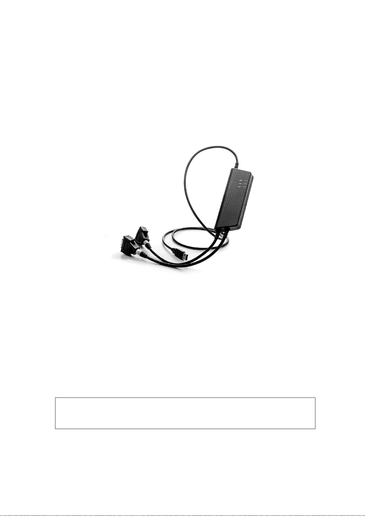
2.3 Interface
Kvaser USBcan Pro 2xHS v2 provides a CAN bus interface through a standardUSB
interface.
2.4 The t programming language
The Kvaser t programming language is event oriented and modelled after C. It canbe used
to customize the behavior of the Kvaser USBcan Pro 2xHS v2 and otherKvaser t capable
devices.
A t program is invoked via hooks, which are entry points that are executed at theoccurrence of
certain events. These events can be, for example, the arrival of specific CAN messages or a
timer expiration.
Like any Kvaser CAN interface, the Kvaser USBcan Pro 2xHS v2 can be used via
CANlib on a host computer. The addition of t programs running directly on the Kvaser
USBcan Pro 2xHS v2 makes it possible to react much quicker to CAN busevents (for
example to speed up file transfer protocols or to simulate missing hardware).
For more information, see the Kvaser t Programming Language guide that can be
downloaded at www.kvaser.com/download.
•
•
•

Kvaser USBcan Pro 2xHS v2 User’s Guide
7 (24)
GMGA MEASURING - Hanoi, Vietnam —https://gmga.vn/
2.5 Restrictions in t functionality
The Kvaser USBcan Pro 2xHS v2 is a dedicated CAN interface, and as such does not
contain real-time clock (RTC), logger or SD card functionality, neither does the Kvaser
USBcan Pro 2xHS v2 include dedicated I/O pins. This means that the
t functionality listed in Table 2 on Page 7 is not available on Kvaser USBcan Pro2xHS
v2 (the table shows version 3.10 of the t language compiler).
Group
Function name
Hooks
on IoEvent
Predefined I/O Functions
kvIoGetNumberOfPins
kvIoPinGetInfo
kvIoPinSetInfo
kvIoConfirmConfig
kvIoPinSetDigital
kvIoPinGetDigital
kvIoPinGetOutputDigital
kvIoPinSetRelay
kvIoPinGetOutputRelay
kvIoPinSetAnalog
kvIoPinGetAnalog
kvIoPinGetOutputAnalog
Predefined File I/O Functions
fileOpen
fileClose
fileGets
fileReadBlock
filePuts
fileWriteBlock
fileSeek
fileDelete
Predefined XML Functions
xmlOpen
xmlClose
xmlGet
Predefined t Program Related Functions
scriptLoad
Predefined Logger Related Functions
filterDropMessage
loggerStatus
loggerStart
loggerStop
Other Predefined Functions
timeGetDate
Table 2: Functionality in the t language (v3.10) that is not supported by Kvaser USBcan
Pro 2xHS v2.

Kvaser USBcan Pro 2xHS v2 User’s Guide
8 (24)
GMGA MEASURING - Hanoi, Vietnam —https://gmga.vn/
2.6 Additional software and documentation
The Kvaser CANlib SDK includes everything you need in order to develop software
applications interacting with Kvaser CAN and LIN hardware. The SDK contains full
documentation and many sample programs, written in C, C++, C#, Delphi, Python and
Visual Basic. Kvaser CAN and LIN hardware is built around the same commonsoftware
API. Applications developed using one device type will run without modification on
other device types.
The latest versions of documentation, software and drivers can be downloaded forfree at
www.kvaser.com/download.

Kvaser USBcan Pro 2xHS v2 User’s Guide
9 (24)
GMGA MEASURING - Hanoi, Vietnam —https://gmga.vn/
3
Kvaser USBcan Pro 2xHS v2 hardware
In this section you can read more about the CAN channels, power supply and LED
indicators.
3.1 Hardware installation
For the Kvaser USBcan Pro 2xHS v2 to communicate with the host computer, a
compatible version of the Kvaser driver and firmware must be installed.
After the driver has been installed on the host computer, the firmware may then bedownloaded
and installed on the Kvaser USBcan Pro 2xHS v2.
The latest version of the driver and firmware can be downloaded from
www.kvaser.com/download.
The driver is installed by running the file kvaser_drivers_setup.exe.
The Kvaser USBcan Pro 2xHS v2 may be inserted in any free USB socket on thehost
computer. You do not need to switch the power off before inserting or removing the
device.
For information on how to upgrade the firmware, see Section 4.6, Updating the
firmware, on Page 16.
3.2 USB connector
The Kvaser USBcan Pro 2xHS v2 has a standard USB type “A” connector.
Figure 2: A standard USB type “A” connector.
Connect the device to your computer using any high quality USB 2.0 certified
cable. The
maximum total USB cable length is 5 m (∼16 ft).

Kvaser USBcan Pro 2xHS v2 User’s Guide
10 (24)
GMGA MEASURING - Hanoi, Vietnam —https://gmga.vn/
3.3 CAN channels
The Kvaser USBcan Pro 2xHS v2 has two CAN channels in two seperate 9-pinD-SUB
CAN connector (see Figure 3). See Section 4.4, CAN connectors, on Page 15 for
pinout information.
Figure 3: CAN connector on Kvaser USBcan Pro 2xHS v2
3.4 Power supply
The Kvaser USBcan Pro 2xHS v2 is powered from the USB port.
3.5 LED Indicators
The Kvaser USBcan Pro 2xHS v2 has one power LED and one traffic LED for eachCAN
channel as shown in Figure 4 on Page 11. Their functions are described in Section 4.1,
Definitions of LED states and colors, on Page 12.
As USB cables become longer they are more sensitive to EMI,
because they make a longer antenna that can pick up more noise.
These issues can be mitigated by using higher quality cables with
better shielding. Thicker cables tend to be better thanthin ones, and
braided shielding tends to be more reliable than only foil. Furthermore,
longer cables may introduce signal degradation and timing issues that,
if necessary, can be mitigatedusing shorter cable segments combined
with hubs that amplify the signal and handle delays on a per-cable
basis.

Kvaser USBcan Pro 2xHS v2 User’s Guide
11 (24)
GMGA MEASURING - Hanoi, Vietnam —https://gmga.vn/
Figure 4: LEDs on the Kvaser USBcan Pro 2xHS v2.
3.6 Troubleshooting
Use “Kvaser Device Guide” in the Control Panel to verify that the computer can
communicate with the Kvaser USBcan Pro 2xHS v2. If the firmware version shownis all
zeros, there are communication problems. If the LEDs are not flashing or donot light up
at all, check the power supply.

Kvaser USBcan Pro 2xHS v2 User’s Guide
12 (24)
GMGA MEASURING - Hanoi, Vietnam —https://gmga.vn/
4
Appendices
In this section you will find technical information about the Kvaser USBcan Pro2xHS
v2 and its connectors.
4.1 Definitions of LED states and colors
A Kvaser device has two basic types of LEDs; Power and Traffic. These are dualcolored
as shown in Table 3. A device with multiple CAN channels has one TrafficLED for each
CAN channel. When the device has more than one channel a spaceand digit is added on
the label, CAN 1, CAN 2 etc. The red Traffic LEDs are alsoused to indicate errors by
using all red Traffic LEDs simultaneously.
LED
Label
Color
Power
PWR
Green/Yellow
Traffic
CAN
Yellow/Red
Table 3: The different type of LEDs.
The following definitions is used to describe the state of an LED:
Off
The LED is off and no light is emitted.
Flash
The LED is lit up for a very short time. A single flash may be hard to seeand a
continuous set of flashes will look the same as On.
Slow Blink
The LED is repeatedly turned On and Off. The On and Off phase isequal
in time.
Fast Blink
The LED is repeatedly turned On and Off but with a higher frequencythan
Slow Blink. The On and Off time is still equal.
On
The LED is constantly emitting light.
Slow Waver
This is a variant of Slow Blink but instead of being Off, a second coloris On.
This is only possible with a dual colored LED.
Fast Waver
The LED is alternating between two colors as in Slow Waver butusing
a higher frequency.
Running
This means that all LEDs are lit, one at the time, in sequence with everycolor
available i.e. “Power green->Power yellow->Traffic 1 yellow->Traffic 1red-
>Traffic 2 yellow->Traffic 2 red->...”
As an example, "Slow Waver (Green/Yellow)" means that the LEDis slowly blinkingby
alternating between green and yellow.

Kvaser USBcan Pro 2xHS v2 User’s Guide
13 (24)
GMGA MEASURING - Hanoi, Vietnam —https://gmga.vn/
The power should never be removed when firmware update is in
progress.
4.1.1
Interface mode
The device is in Interface mode when connected to the host computer via USB. If the
Power LED is showing a steady green light, the device is in Interface mode andworking
correctly. When connected to the computer for the first time, the Power LED will blink
slowly in yellow until the driver is installed and the device has received a USB
configuration.
When in Interface mode, if the Power LED is yellow for an extended period,
something is wrong. Please see Table 4.
Power LED
Traffic LED
Description
Slow Blink (Yellow)
All off (-)
Waiting for USB configuration
Slow Waver (Green/Yellow)
Slow Waver (Yellow/Red)
Firmware configuration error1
Slow Waver (Green/Yellow)
All Slow Blink (Yellow)
Power problem2
Table 4: Yellow Power LED shows problems inInterface mode.
Traffic LED
Description
Off (-)
Idle, no CAN traffic
Flash (Yellow)
CAN message received or sent
Flash (Red)
Error frame received
All Fast Blink (Yellow)
Firmware update is in progress
Fast Blink (Red)
CAN channel is error passive
On (Red)3
CAN overrun
Table 5: Traffic LED shows CAN bus status in Interface mode .
4.1.2
Status of scripts
There are by default no LED indications showing the state of a t program. Instead,the
developer of a script can override any of the existing LEDs and create notifications as
needed when the t program is running, including program exceptions.
1This should not normally happen. If it does, please contact Kvaser support.
2This indicates low power supply, such as using an unpowered USB hub.
3The red Traffic LED indicating overrun will stay on until the device goes bus off.

Kvaser USBcan Pro 2xHS v2 User’s Guide
14 (24)
GMGA MEASURING - Hanoi, Vietnam —https://gmga.vn/
4.2 Start and stop of t programs
All events that a t program will react to are specified using various event hooks. In effect,
these are functions which are called when the specific events occur. Amongother events,
the program can react to starting and stopping itself which this section describes. Read
the Kvaser t Programming Language guide that can be downloaded at
www.kvaser.com/download for more information.
The “on start” event will be triggered in the Kvaser USBcan Pro 2xHS v2 when anyof the
following occurs:
•
When a t program is started using the CANlib API (kvScriptStart()).
•
When a t program is started from another t program.
The “on stop” event will be triggered for running t programs during thecorresponding
cases:
•
When a t program is stopped using the CANlib API (kvScriptStop()).
•
When a t program is stopped from another t program.
4.3 Technical data
In Table 6 you will find the technical specifications of Kvaser USBcan Pro 2xHS v2.
CAN Channels
2
CAN Transceivers
MCP2561FD (Compliant with ISO 11898-2)
CAN Controller
Kvaser CAN IP in FPGA
Galvanic isolation
Yes
CAN Bit Rate
50 kbit/s to 1 Mbit/s
CAN FD Bit Rate
Up to 8 Mbit/s (with correct physical layer implementation)
Time stamp resolution
1 µs
Max message rate
20000 msg/s per channel
Error Frame Detection
Yes
Error Frame Generation
Yes
Silent mode
Yes
Kvaser MagiSync
Yes
Kvaser CANtegrity
Yes
Host interface
USB Hi-Speed
Host OS
Windows (7 or later), Linux, Android.
Power consumption
max 500 mA
Hardware configuration
Done by software (Plug & Play).
Dimensions
50 x 170 x 20 mm for body incl. strain relief
Weight
170 g
Operating temperature
−40
◦
C to +85
◦
C
Storage temperature
−40
◦
C to +85
◦
C
Relative humidity
0 % to 85 % (non-condensing.)
Table 6: Technical Specifications.

Kvaser USBcan Pro 2xHS v2 User’s Guide
15 (24)
GMGA MEASURING - Hanoi, Vietnam —https://gmga.vn/
To save yourself a lot of trouble, always terminate the CAN
bus
properly.
4.4 CAN connectors
Kvaser USBcan Pro 2xHS v2 devices that use the 9-pin D-SUB connector (seeFigure
5 on Page 15) have the pinning described in Table 7 on Page 15.
Figure 5: The D-SUB 9 connector pin numbers
D-SUB pin number
Function
1
Not connected
2
CAN_L
3
GND
4
Not connected
5
Shield
6
Not connected
7
CAN_H
8
Not connected
9
Not connected
Table 7: Configuration of the 9-pin D-SUB
4.5 CAN bus termination
Every CAN bus must be terminated with a 120 Ohm resistor at each end of the bus. The
Kvaser USBcan Pro 2xHS v2 does not contain any CAN bus termination,because their
inclusion could cause severe disturbance in a system which is already correctly
terminated.
For laboratory or testing use, the exact value of the termination resistors is not always
critical. Sometimes a single terminator is sufficient. For production, propertermination is
essential. If you see error frames on the bus, you should check the termination.

Kvaser USBcan Pro 2xHS v2 User’s Guide
16 (24)
GMGA MEASURING - Hanoi, Vietnam —https://gmga.vn/
4.6 Updating the firmware
For the Kvaser USBcan Pro 2xHS v2 to communicate with the host computer,
compatible versions of the Kvaser CANlib (including driver) and firmware must be
installed.
The latest versions of firmware and drivers can be downloaded for free at
www.kvaser.com/download.
Connect the Kvaser USBcan Pro 2xHS v2 to your host computer
with the USB cable and start the update.exe application. A window opens showingthe
Firmware Update Instructions, read and follow those carefully.
To check the current firmware version, open “Kvaser Device Guide” which can be
found
in the Control Panel. Select “Kvaser USBcan Pro 2xHS v2” in the tree viewto the left,
and click on the channel. The firmware revision information now appears in the right
half of the window.
The absolute minimum firmware and driver versions needed in order to use KvaserUSBcan
Pro 2xHS v2 are listed in Table 8
Device
Min. Firmware Version
Min. Driver Version
Kvaser USBcan Pro 2xHS v2
v2.6.462
V5.12
Table 8: Minimum compatible driver and firmware versions of Kvaser USBcan Pro2xHS
v2.
4.7 Kvaser MagiSync
Time synchronization is needed to achieve accurate and precise time stamping between
several host computer-to-bus interfaces connected to one host computer.Since each host
computer-to-bus interface uses its on-board clock to set the time stamps.
Kvaser MagiSync is an innovative way to synchronize several different Kvaser USB
interfaces. You do not need external cables - you get instant synchronisation when you
connect the MagiSync enabled Kvaser USB device.
For this to work the Kvaser USB interfaces must reside on the same USB root hub.If they
do not they will not be synchronized, see Figure 6 on Page 17 and Figure 7 on Page 17.
Usually, a computer has a USB controller with one root hub in a computer. If you use
that one, you do not need an external USB hub to get your Kvaser Devices
synchronized. The easiest way to verify the setup is to view Synchronized Hardware in
the Device Tree of “Kvaser Device Guide” in your computer’s control panel. If all your
hardware is placed in one Kvaser MagiSync Group, then you areready to go.
When connected correctly, all units are synchronized achieving a high precisionvirtual
clock accurate to the microsecond.

Kvaser USBcan Pro 2xHS v2 User’s Guide
18 (24)
GMGA MEASURING - Hanoi, Vietnam —https://gmga.vn/
4.8 Kvaser CANtegrity
Kvaser CANtegrity is an extension to the logic of the CAN FD controller that
provides deeper knowledge about each CAN frame. With this knowledge it is
possible to provide the following information:
•
A digital oscilloscope view on the CAN frames.
•
Bit length deviations over time.
•
Asymmetric propagation delays for dominant and recessive bits.
The Kvaser CANtegrity logic may run different event programs depending on whattype of
information that should be collected. As an example, one such event program will search
for CAN frames according to a defined bit rate and will record everything that looks like
a CAN frame, including Error frames.
Figure 8 shows an example of visualizing the information retrieved by the Kvaser
CANtegrity function included in the Kvaser USBcan Pro 2xHS v2 (00752-9). More
information about Kvaser CANtegrity can be found on https://www.kvaser.com/kvaser-
cantegrity/.
Figure 8: Using information from Kvaser CANtegrity, the time between two edgescan be
measured.

Kvaser USBcan Pro 2xHS v2 User’s Guide
19 (24)
GMGA MEASURING - Hanoi, Vietnam —https://gmga.vn/
5
Disposal and Recycling Information
When this product reaches its end of life, please dispose of it
according to your local environmental laws and guidelines.
For information about Kvaser’s recycling programs, visit:
https://www.kvaser.com/en/kvaser/recycling-policy.html

Kvaser USBcan Pro 2xHS v2 User’s Guide
20 (24)
GMGA MEASURING - Hanoi, Vietnam —https://gmga.vn/
6
Legal acknowledgements
6.1 Usage warning
WARNING FOR ALL USERS
WARNING! - YOUR USE OF THIS DEVICE MUST BE DONE WITH CAUTION AND A FULL
UNDERSTANDING OF THE RISKS!
THIS WARNING IS PRESENTED TO INFORM YOU THAT THE OPERATION OF THIS DEVICE
MAY BE DANGEROUS. YOUR ACTIONS CAN INFLUENCE THE BEHAVIOR OF A CAN-BASED
DISTRIBUTED EMBEDDED SYSTEM, AND DEPENDING ON THE APPLICATION, THE
CONSEQUENCES OF YOUR IMPROPER ACTIONS COULD CAUSE SERIOUS OPERATIONAL
MALFUNCTION, LOSS OF INFORMATION, DAMAGE TO EQUIPMENT, AND PHYSICAL INJURY
TO YOURSELF AND OTHERS. A POTENTIALLY HAZARDOUS OPERATING CONDITION IS
PRESENT WHEN THE FOLLOWING TWO CONDITIONS ARE CONCURRENTLY TRUE: THE
PRODUCT IS PHYSICALLY INTERCONNECTED TO A REAL DISTRIBUTED EMBEDDED
SYSTEM; AND THE FUNCTIONS AND OPERATIONS OF THE REAL DISTRIBUTED EMBEDDED
SYSTEM ARE CONTROLLABLE OR INFLUENCED BY THE USE OF THE CAN NETWORK. A
POTENTIALLY HAZARDOUS OPERATING CONDITION MAY RESULT FROM THE ACTIVITY
OR NON-ACTIVITY OF SOME DISTRIBUTED EMBEDDED SYSTEM FUNCTIONS AND
OPERATIONS, WHICH MAY RESULT IN SERIOUS PHYSICAL HARM OR DEATH OR CAUSE
DAMAGE TO EQUIPMENT, DEVICES, OR THE SURROUNDINGENVIRONMENT.
WITH THIS DEVICE, YOU MAY POTENTIALLY:
CAUSE A CHANGE IN THE OPERATION OF THE SYSTEM, MODULE, DEVICE,
CIRCUIT, OR OUTPUT.
TURN ON OR ACTIVATE A MODULE, DEVICE, CIRCUIT, OUTPUT, OR FUNCTION.
TURN OFF OR DEACTIVATE A MODULE, DEVICE, CIRCUIT, OUTPUT, OR
FUNCTION.
INHIBIT, TURN OFF, OR DEACTIVATE NORMAL OPERATION.
MODIFY THE BEHAVIOR OF A DISTRIBUTED PRODUCT. ACTIVATE
AN UNINTENDED OPERATION.
PLACE THE SYSTEM, MODULE, DEVICE, CIRCUIT, OR OUTPUT INTO AN
UNINTENDED MODE.
ONLY THOSE PERSONS WHO:
(A) ARE PROPERLY TRAINED AND QUALIFIED WITH RESPECT TO THE USE OF THE
DEVICE,
(B) UNDERSTAND THE WARNINGS ABOVE, AND
(C) UNDERSTAND HOW THIS DEVICE INTERACTS WITH AND IMPACTS THE FUNCTION
AND SAFETY OF OTHER PRODUCTS IN A DISTRIBUTED SYSTEM AND THE APPLICATION
FOR WHICH THIS DEVICE WILL BE APPLIED, MAY USE THE DEVICE.
PLEASE NOTE THAT YOU CAN INTEGRATE THIS PRODUCT AS A SUBSYSTEM INTO
HIGHER-LEVEL SYSTEMS. IN CASE YOU DO SO, KVASER AB HEREBY DECLARES THAT
KVASER AB’S WARRANTY SHALL BE LIMITED TO THE CORRECTION OF DEFECTS, AND
KVASER AB HEREBY EXPRESSLY DISCLAIMS ANY LIABILITY OVER AND ABOVE THE
REFUNDING OF THE PRICE PAID FOR THIS DEVICE, SINCE KVASER AB DOES NOT HAVE
ANY INFLUENCE ON THE IMPLEMENTATIONS OF THE HIGHER-LEVEL SYSTEM, WHICH
MAY BE DEFECTIVE.
•
•
•
•
•
•
•
Table of contents