2 D5040 - SIL 3 Digital Output Driver G.M. International ISM0187-9
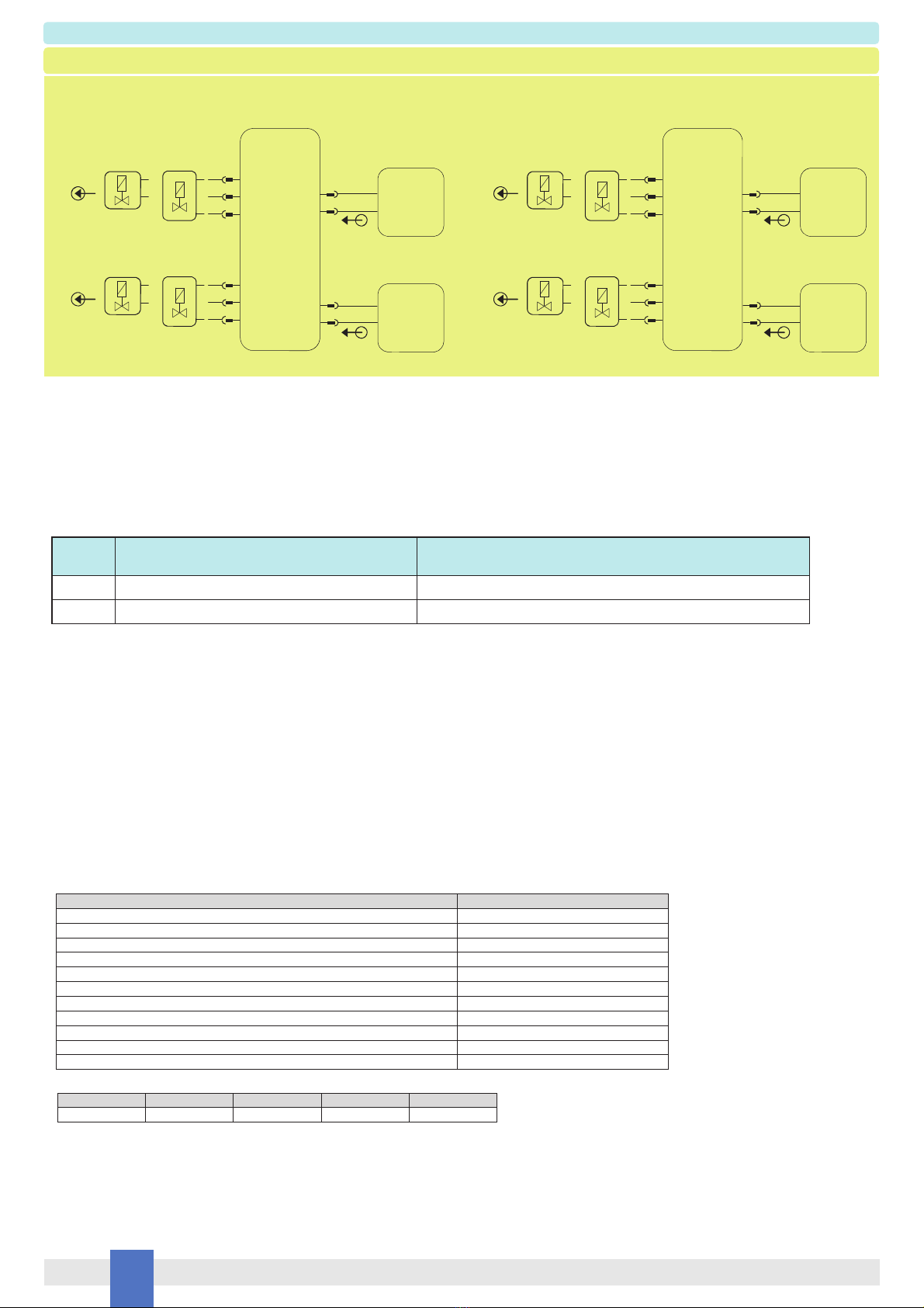
General Description: The single or dual channel Loop Powered Digital Output Isolators, D5040S and D5040D, are suitable for driving solenoid valves, visual or audible alarms to alert a
plant operator, or other process control devices in Hazardous Area from driving signals in Safe Area. They can also be used as controllable supplies to power measuring or process
control equipment.
Their use is allowed in applications requiring up to SIL 3 level (according to IEC 61508:2010 Ed. 2) in safety related systems for high risk industries. The Safety PLC or DCS driving
signals control the field devices through D5040S and D5040D, which provide isolation. For each channel two basic output circuits are selectable, with different safety parameters, to
interface the majority of devices on the market. The selection among the two output characteristics is obtained by connecting the field device to a different couple of terminal blocks.
Mounting on standard DIN-Rail or on customized Termination Boards, in Safe Area / Non Hazardous Location or in Zone 2 / Class I, Division 2 or Class I, Zone 2.
Functional Safety Management certification:G.M. International is certified by TUV to conform to IEC61508:2010 part 1 clauses 5-6
for safety related systems up to and included SIL3.
Technical Data
Characteristics
Loop Input:
loop powered control signal.
Loop Supply: 24 Vdc nom (18 to 30 Vdc) reverse polarity protected, 2 A time lag fuse internally protected.
Current consumption @ 24 V: 45 mA with 30 mA output for each channel of D5040D, typical in normal operation. 55 mA with 40 mA output (typical for D5040S).
Power dissipation: 0.75 W with 24 V supply, output energized at 35 mA nominal load for each channel of D5040D; 0.85 W with 24 V supply, output energized at 45 mA nominal load
for D5040S.
Isolation (Test Voltage):
I.S. Out/In 1.5 KV.
Out/Out 500 V.
In/In 500 V.
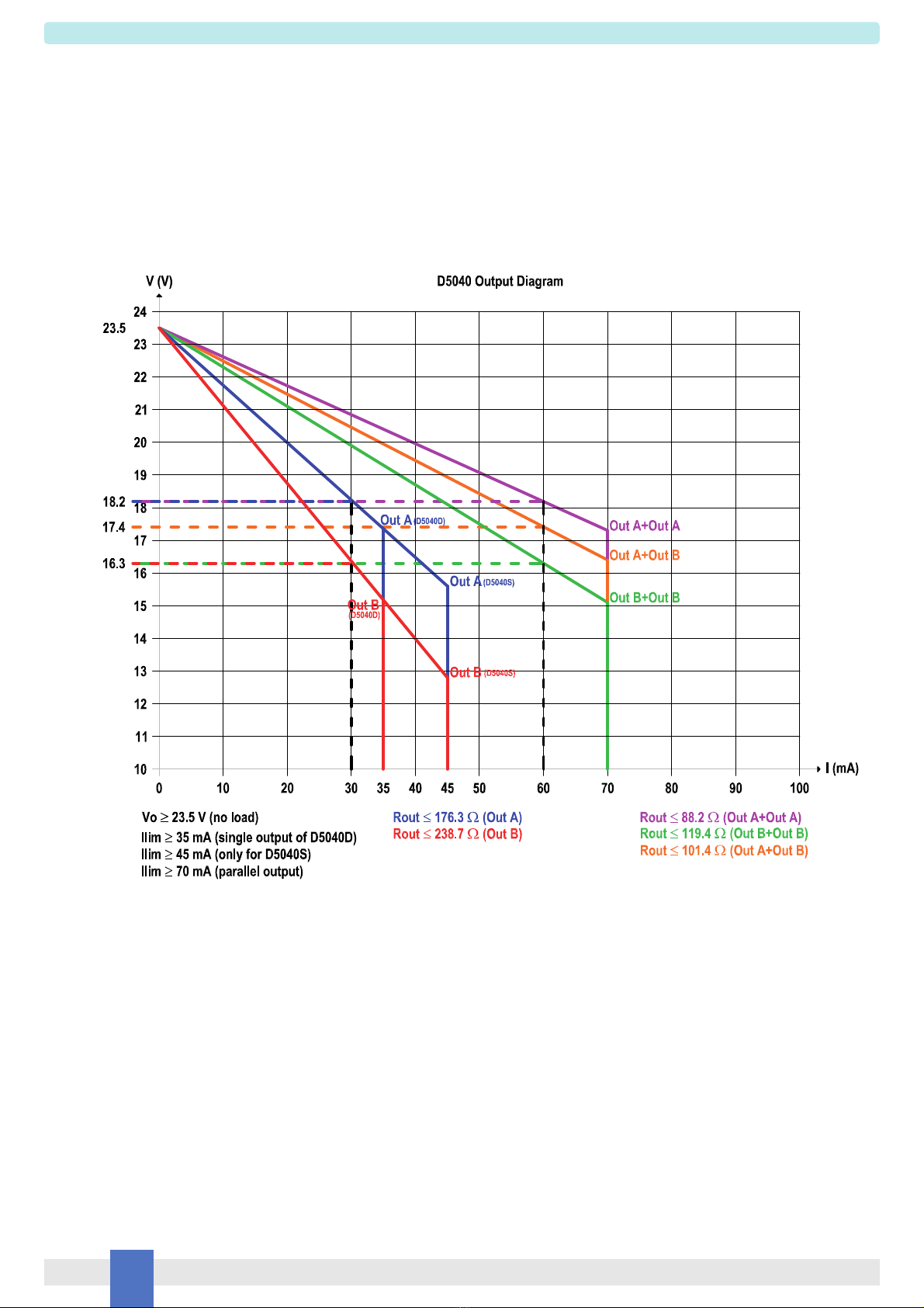
Output:
See next page for detailed output diagrams and characteristics.
Short circuit current:
≥45 mA (50 mA typical) for single output configuration (D5040S);
≥35 mA (40 mA typical) for single output configurations (D5040D);
≥70 mA (80 mA typical) for parallel output configurations (D5040D).
Response time: ≤75 ms.
Frequency response: 50 Hz
Compatibility:
CE mark compliant, conforms to Directive: 2014/34/EU ATEX, 2014/30/EU EMC, 2014/35/EU LVD, 2011/65/EU RoHS.
Environmental conditions:
Operating: temperature limits – 40 to + 70 °C, relative humidity 95 %, up to 55 °C.
Storage: temperature limits – 45 to + 80 °C.
Safety Description:
ATEX: II 3(1)G Ex ec [ia Ga] IIC T4 Gc, II (1)D [Ex ia Da] IIIC, I (M1) [Ex ia Ma] I
IECEx: Ex ec [ia Ga] IIC T4 Gc, [Ex ia Da] IIIC, [Ex ia Ma] I,
UL: NI / I / 2 / ABCD / T4, AIS / I, II, III / 1 / ABCDEFG, AEx nA [ia Ga] IIC T4 Gc
C-UL: NI / I / 2 / ABCD / T4, AIS / I, II, III / 1 / ABCDEFG, Ex nA [ia Ga] IIC T4 Gc
EAC-EX: 2Ex nA [ia Ga] IIC T4 Gc X, [Ex ia Da] IIIC X, [Ex ia Ma] I X
CCC: Ex nA [ia Ga] IIC T4 Gc; [Ex ia Ga] IIC; [Ex iaD]
UKR TR n. 898: 2ExnAiaIICT4 X, ExiaI X
KCs: Ex nA [ia Ga] IIC T4 Gc
associated apparatus and non-sparking electrical equipment.
See next page for safety parameters.
Um = 250 Vrms, -40 °C ≤Ta ≤70 °C.
Approvals:
BVS 14 ATEX E 159 X conforms to EN60079-0, EN60079-7, EN60079-11.
IECEx BVS 14.0111X conforms to IEC60079-0, IEC60079-7, IEC60079-11.
UL & C-UL E222308 conforms to UL913, UL 60079-0, UL60079-11, UL60079-15, ANSI/ISA 12.12.01 for UL
and CSA-C22.2 No.157-92, CSA-E60079-0, CSA-E60079-11, CSA-C22.2 No. 213 and CSA-E60079-15 for C-UL.
ЕАЭС RU С-IT.EX01.B.00018/19 conforms to GOST 31610.0, GOST 31610.11, GOST 31610.15.
CCC n. 2020322316000978 conforms to GB 3836.1, GB3836.4, GB3836.8, GB12476.1, GB12476.4
CЦ16.0036 X conforms to ДСТУ 7113, ГОСТ 22782.5-78, ДСТУ IЕС 60079-15.
KTL 16-KA4BO-443X for KCs approval (for D5040S).
KTL 16-KA4BO-444X for KCs approval (for D5040D).
TÜV Certificate No. C-IS-236198-04, SIL 3 conforms to IEC61508:2010 Ed.2.
TÜV Certificate No. C-IS-236198-09, SIL 3 Functional Safety Certificate conforms to IEC61508:2010 Ed.2, for Management of Functional Safety.
DNV Type Approval Certificate No. TAA00001U0 and KR No.MIL20769-EL002 Certificates for maritime applications.
Mounting:
EN/IEC60715 TH 35 DIN-Rail or on customized Termination Board.
Weight: about 110 g.
Connection: by polarized plug-in disconnect screw terminal blocks to accomodate terminations up to 2.5 mm2.
Location: installation in Safe Area/Non Hazardous Locations or Zone 2, Group IIC T4 or Class I, Division 2, Group A,B,C,D, T4 or Class I, Zone 2, Group IIC, T4.
Protection class: IP 20.
Dimensions: Width 12.5 mm, Depth 123 mm, Height 120 mm.
FSM
SIL 3