8
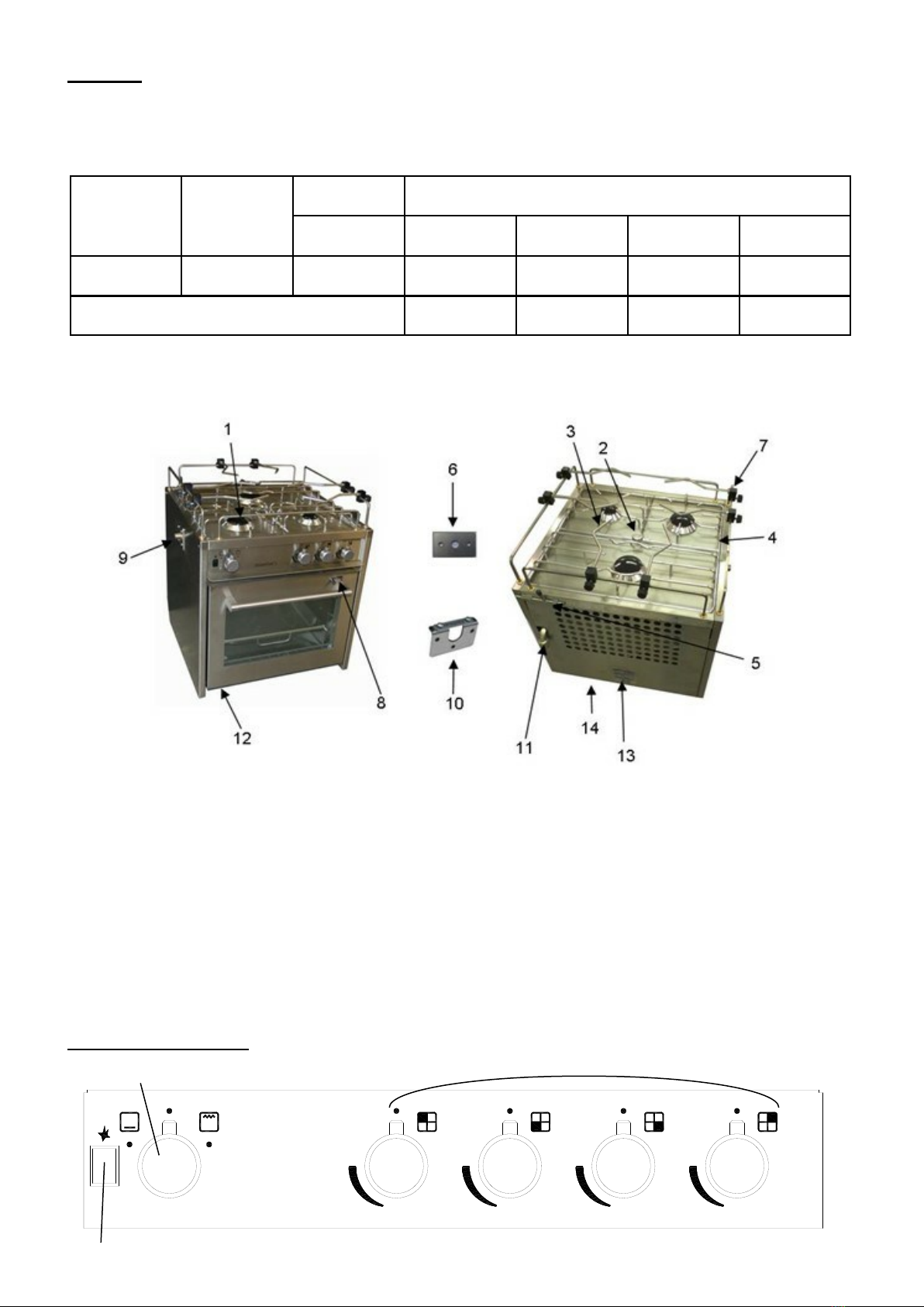
Using the Oven
Shelf Positions
The oven has three shelf positions—top (for grilling), middle and lower.
Heat zones
When using the oven you will find that the top shelf of the oven cavity is hotter that the lower shelf. The oven temperature that you have
chosen will be on the middle shelf.
You may therefore have to adjust the temperature or cooking time depending on which shelf level you are using in the oven.
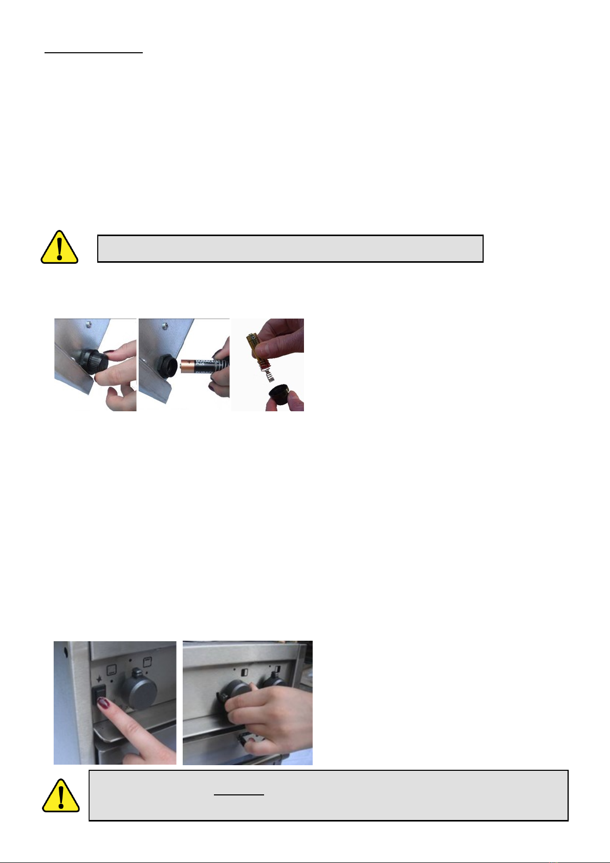
1. To remove the oven shelf pull it out
until it reaches the safety stop.
2. Slightly angle the shelf upwards and
pull out of the runners.
The oven is supplied with two removable oven shelf pan holder as standard.
Additional oven shelf pan holders are available as optional accessories.
Preheating
Important: when you need to preheat the oven, we recommend you do so for at least 15 minutes (20 minutes when cooking large amounts of
food). Placing cold food in an oven that has not been pre-heated considerably reduces the cooking performance.
Oven thermostat
Immediately initiate repair or replacement of the thermostat if an abnormal drift of oven temperature occurs during cooking.
Oven
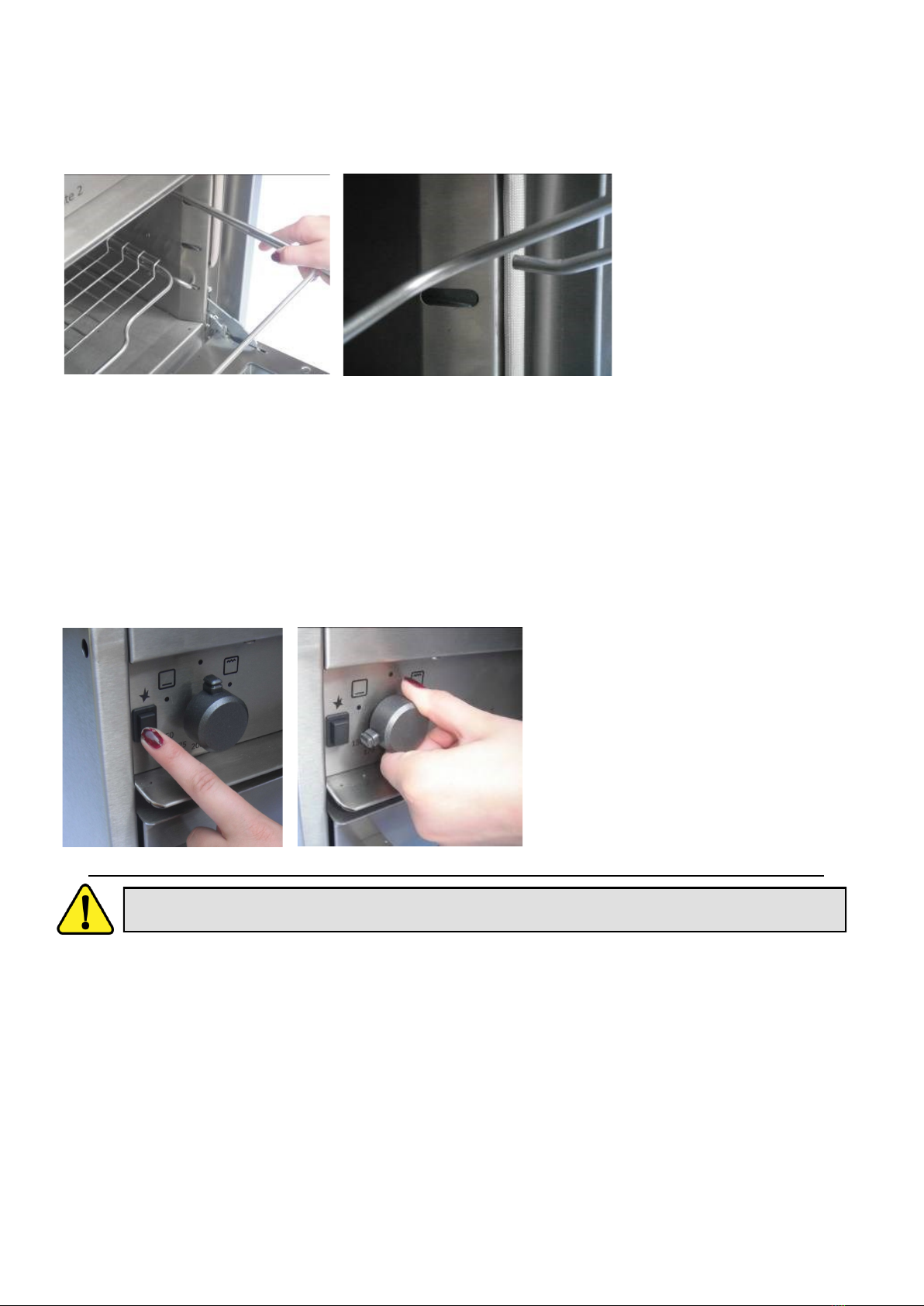
To Light Oven:
1. Open the oven door.
2. Push in the control knob and turn it to the maximum
oven setting. Keep the control knob pushed in and
press the ignition button immediately.
3. When the burner has lit, release the ignition button,
but keep holding in the control knob for 15 seconds
(to heat the thermocouple)
4. Release the control knob and then turn it to the re-
quired setting.
5. Wait until the burner is showing large flames.
6. Close the oven door.
WARNING : Press the ignition button immediately. If not pressed immediately then a build up of gas may cause
the flame to spread.
If the burner flame is accidentally extinguished during cooking, turn off the gas and wait at least one minute before attempting to re-ignite.
To turn off any burner (hob, grill and oven)
1. Push in the control knob and turn it to the off position. This is shown by a large dot.
Cooking
The oven is designed to accept standard and Gastronorm cooking trays which are available in a number of sizes and depths.
There are 3 shelf positions.
Always pre-heat the oven before placing cold food in the oven.
The oven is capable of reaching full cooking temperature from cold, in approximately 20 minutes.
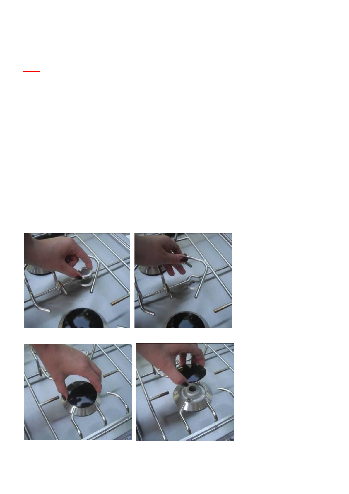
When using the hotplate, care must be taken to ensure that pans do not overlap the edges of the hotplate. When circular pans are used the
minimum diameter shall not be less than 120mm and the maximum shall be 180mm, on all the burners.
Oven Temperature Control: MINIMUM SETTING AVG. TEMP = 112oC / MAXIMUM SETTING AVG. TEMP = 236oC