5Fury X-3 Installaon and Operang Instrucons
INSTALLATION
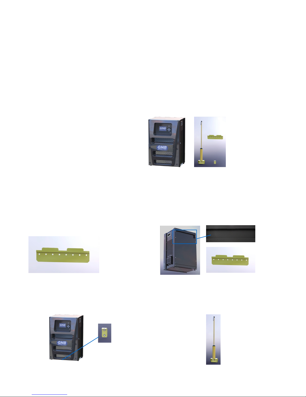
Wall Mount Installaon
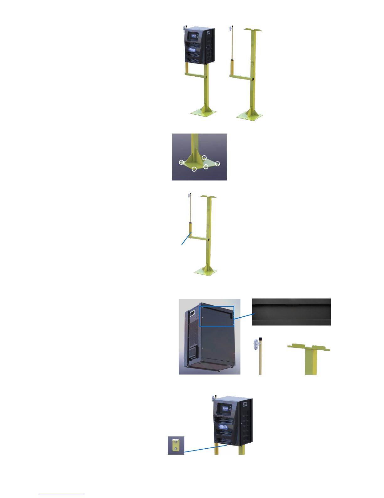
Wall mounng hangers with a pogo are available for
installaon. The gure illustrates the various parts for a
typical wall mount charger installaon:
Step 1. Bolt the Wall Mount Hanger to the Wall
Secure the wall mount hanger to the concrete wall through
the pre-drilled holes in the hanger. Ensure the two ns are
facing up. Mount to a solid concrete wall through holes using
bolts into wall anchors – check with professional installaon
personnel to determine proper mounng techniques for all
wall types.
Step 2. Hang the Charger on the Wall Mount
Hang the charger on the wall mount hanger so that the two
slits on the back of the charger line up with the two ns of
the hanger.
Step 3. Mount the Boom Brace to the Charger and Wall Step 4. Mount the Pogo Wall Bracket to the Wall
and Aach the Pogo
Top
Boom
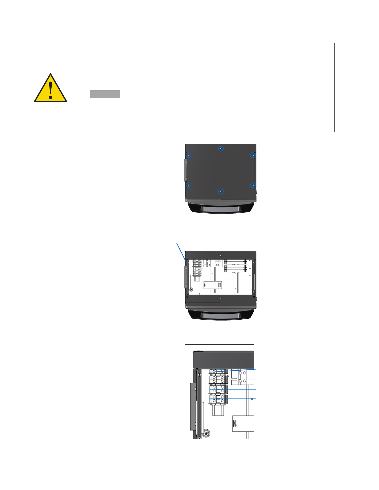
Installaon must only be carried out by suitably qualied personnel and in accordance with current local and naonal wiring regulaons.
Baery leads should not be altered without prior consultaon with service personnel.
The charger should be sited in a cool, dry, well-venlated locaon away from corrosive fumes and humid atmospheres. Ambient temperature range
must be maintained between 32°F-104°F.
Ensure venlaon is not obstructed at the le air intake and right exhaust vents.
The charger is for indoor use only.
Before installaon, check that the charger has not sustained any damages during transit. Make sure the electrical rangs are suitable for both the
intended AC input supply and the DC output current and voltage for the baeries to be charged. Also ensure that the connector polarity is correct
and matches the polarity of the baery connector.
CAUTION – To reduce the risk of re, use only on circuits provided with branch circuit protecon consistent with the current indicated on theFactory
Charger Conguraon label and in accordance with the Naonal Electrical Code, ANSI/NFPA 70 or equivalent.
The circuit breakers rang should be based on the charger's maximum input current, as stated on the Factory Charger Conguraon label. (See the
Technical Specicaons page for more details)