As a power saving feature the LCD backlight will be switched off
after 1 minute of inactivity, the backlight can be turned back on by
briefly pressing any of the buttons. During this time the charge
status indicator will show indication 7.
Charging
When a battery is connected to the charger, charge will start
automatically. The charge status indicator will show indication 1 or
indication 2 (The speed of the rotation indicates the state of charge
of the battery, with fast cycling indicating a low charge state) and
the LCD Display will show the following:
The bar graph display gives the user an indication of the batteries
present state of charge.
During charge, the user can scroll through the following charge
information, by pressing the or keys.
• VPC Voltage per cell
• Ah Total Ampere hours delivered to the battery
• Amps The present output current
• Stage The present charge stage
• Charge Time The total charge time
• Rest Time Time elapsed since charge completed
• Warnings Displays any warnings - Only shown when
applicable
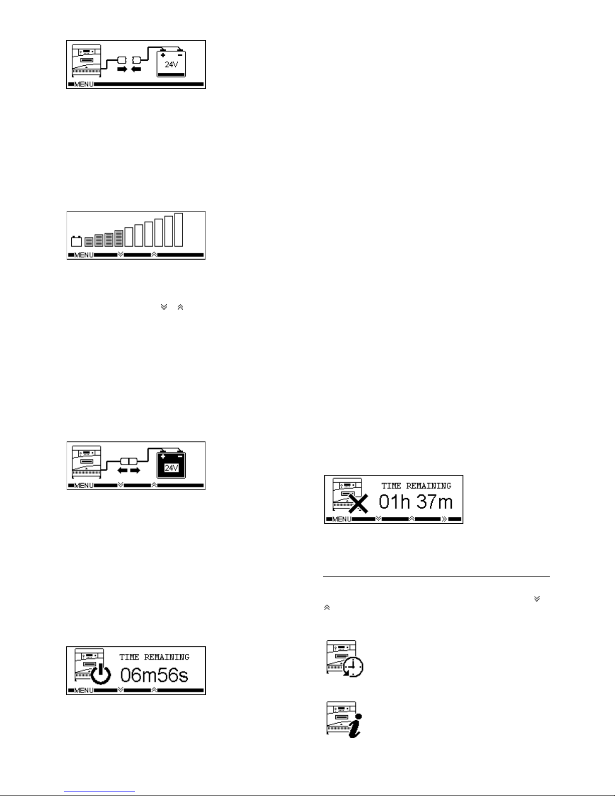
Charge Complete
When charge is complete the charge status indicator will show
indication 3 and the LCD Display will show the following:
If the Auto Balance feature is enabled the battery should be left
connected to the charger until required; under these conditions the
battery will receive periods of refreshing charge to maintain it in the
fully charged condition. During these periods, the charge status
indicator will show indication 4.
Removing the battery
The battery can only be disconnected when charging current
has stopped flowing. Therefore, the pause button must be
pressed before disconnection. A second press of the pause key
will clear the pause condition and continue charge (Disabled
during the first 10 seconds of pause).
When the charger is paused the charge status indicator will show
indication 6 and the LCD Display will show the following:
If the pause mode is entered but the battery is not removed within
10 minutes the charge will automatically continue.
Equalize Mode (Profile Dependant)
Periodically, batteries require additional charging to equalize all of
the cells to the same charge state, this should be performed after
the standard charge has completed.
This mode can be enabled by pressing the = key during the charge
cycle, a second press will clear this function. The equalize function
can not be c leared once it has started and onl y one equalize is
allowed per cycle.
In addition to enabling equalize manually, the equalize feature can
be set to initiate automatically by configuring the automatic
equalize feature in the programming mode. Automatic equalize
may be set to occur every 0 to 250 cycles. Once set the A=
symbol will be shown in the top right corner of the LCD Display.
Once enabled, the charger will perform the equalize function after
the standard charge has been completed.
Battery Recover Mode
If a bat tery is connected to the charger that is below the normal
operating voltage an incorrect battery fault (F07) will be displayed.
However if the battery voltage is between 1 and 1. 5VPC, battery
recover mode is available. This mode employs a special charging
technique to recover batteries that have been left unused for a
long time or have been over discharged.
This mode can be enabl ed by pressing the BRM key when the
fault is displayed. Battery recover mode will then start; once the
battery voltage has been r ecovered to a normal level a standard
charge will be performed.
Cool Down Mode (Profile Dependant)
Cool down mode is activated after the charge has completed and
allows the battery time to ‘cool down’ before its next use. During
this time the battery should remain connected to the charger, but
can be removed if required.
Delayed Start
Note: This function is only available if the network function is OFF
and can only be set without a battery connected.
The delayed start function will delay the start of charge for a s et
time up to 48 hour s in 15 minute increments. The timer begins
count down upon connection to a battery.
During the delay period the charge status indicator will show
indication 6 and the LCD Display will show the following:
Once the time period has elapsed, charge will start as normal. This
can be overridden by pressing the >> button, for this cycle only.
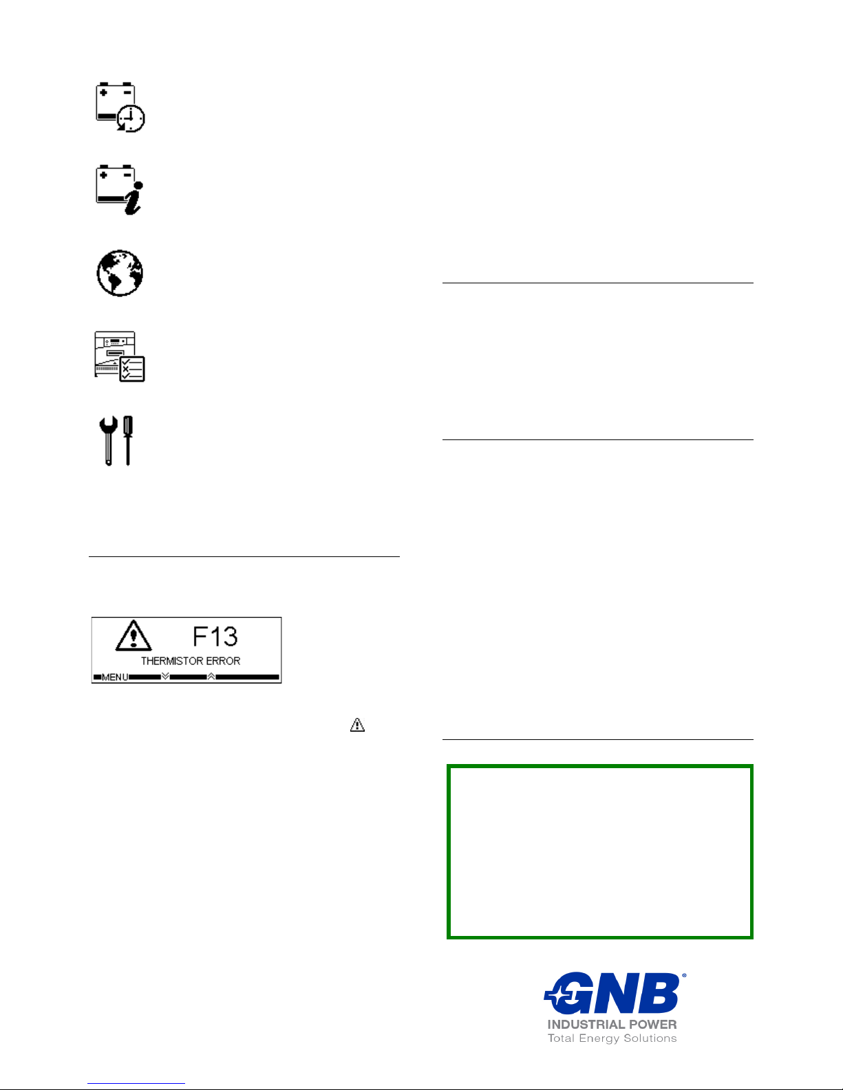
User menu
A user menu can be ac cessed by pressing the MENU key, the
following options can then be scrolled through by pressing the or
keys and then activated by pressing the SELECT key:
Charger History
Cycle Data Total Charge Ah
Cycle Graphs Total Charge Time
Total Initiations
Total Terminations