Gnom Rov SuperPRO User manual

Underwater remotely
operated vehicle
GNOM
Underwater remotely
operated vehicle
for
inspections
GNOM
PRO
Operator manual
2020
Underwater remotely
inspections

v09/2020
2
TABLE OF CONTENTS
Warning!!!
High voltage on cable!
Do not touch the cable in water during operation!
In case any damage occurs on the cable surface, it must be changed or
repaired!
Attention! AC power maximum 240V!
1. Description 3
1.1 Purpose 3
1.2 Technical specifications 4
1.3 Basic complete set 5
2. User’s manual for operation with GNOM 6
2.1 Surface control module 6
2.2 Deployment 8
2.3 Operation 11
3. Keys and buttons at the control panel 14
3.1 Keys and Buttons at the joystick 14
3.2 Keys and Buttons at the LYYN 15
3.3 Screen modes 16
4. Maintenance operation 17
5. Safety requirements 18
6. Warranty statement 19
7. Examples of linking modules 20
8. Appendix 21
9. Annex 23

v09/2020
3
1. DESCRIPTION
1.1 PURPOSE
LIST OF ABBREVIATIONS:
Underwater module
Surface control module
Protective polypropylene frame
Hand reel
Joystick
Digital video recorder
Computer
Monitor
Waterproof case
Grabber
Sector sonar
USBL positioning system
Remotely operated underwater vehicle GNOM is intended for inspection of underwater wrecks
and other objects by video camera.
The device uses modern computer and telecommunication technologies that make it easy to handle,
compact, light, and inexpensive.
These solutions allowed us to use thin and flexible communication cable for transmission of data,
power, and video signal to/from the vehicle. Using the special Kevlar threads helped to improve the
tensile strength of the cable and to keep the highest degree of stabilization very important for
inspections. The vehicle has good maneuverability and can easily turn on the spot.
High-effective electric motors with magnetic couplings and hi-tech electronics provide high speed of the
GNOM with low power consumption.
One of the most important features of this device is a possibility to operate it from PC and via
LAN/Internet.
The GNOM is an underwater helicopter with the video camera that moves in any direction according to
the operator instructions.
Two DC motors inserted in the aluminium halls serve as the thrusters. The rotation is transmitted to the
screw propeller using magnetic coupling disks. One on them is fastened to the motor shaft inside the
body, and the other one to the screw propeller shaft inside the cone-shaped head. The head is filled up
with water and may be removed by the operator for cleaning (see manual).

v09/2020
4
1. DESCRIPTION
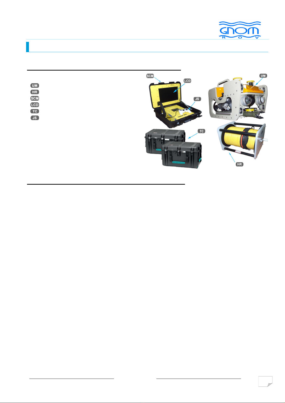
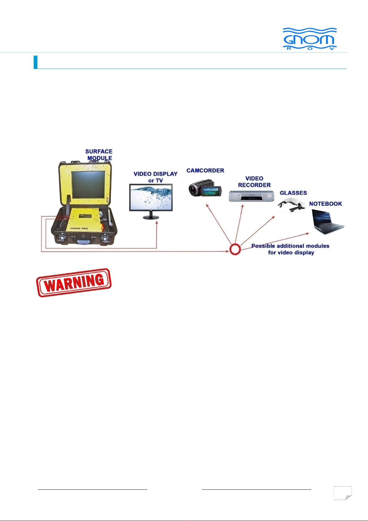
The vehicle is connected with the surface unit via thin cable transmitting power voltage, operation
instructions, data, and video signal from the vehicle.
The cable with diameter 6mm is strengthened by Kevlar threads (breaking effort is 200kg) and by
additional polyethylene shield. The maximum cable length is up to 400m. To counerbalance the weight
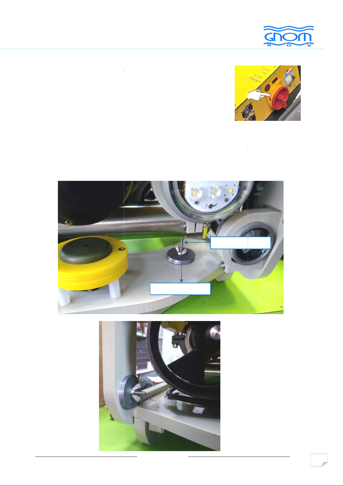
of the vehicle and give it a neutral buoyancy, the foam polystyrene float is installed in the front part of
the vehicle. Similar floats can be put on the cable to change the neutral buoyancy to a little positive.
Maximal operating depth of the vehicle is 150m.
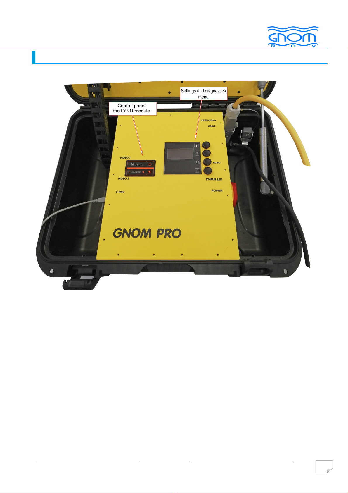
Using the control pads and joystick, the operator can move GNOM forward and backward, turn to the
right and left, up and down; adjust the thruster speed and the brightness of the lights. All data is
displayed on the monitor in the "TV-text" mode. By pressing one of the buttons on the joystick, the
operator can enter the menu to tune up some of the functions – calibrate the depth sensor and the
compass, as well as some other functions.
1.2
TECHNICAL SPECIFICATION
Speed:
horizontal motion, up to 1,5 m/s
vertical motion, up to 0.5 m/s
lateral motion, up to 0.5 m/s
(above numbers depend on a length of the cable)
Max operating depth 150 m
Power voltage 100-230VAC 2000 Watts
Operating temperature range from -5 to +45°C
Operating environment humidity up to 100%
Weight of the vehicle 25 kg
Full weight of the system 100 kg
Dimensions of vehicle (WxLxH) 440х650х360 mm
Tether:
diameter 11 mm
length up to 400 m

v09/2020
5
1. DESCRIPTION
1.3
BASIC COMPLETE SET
ROV GNOM SuperPRO basic complete set
- ROV GNOM SuperPRO
- Hand reel with tether
- Surface control/power unit with joystic
- LCD monitor 15“
- 3x waterproof transport cases
- Joystic
ROV GNOM SuperPRO OPTIONAL modules
The basic set can be extended by the following modules:
a) maging sonar BlueView
b) Sector sonar Tritech Micron
c) USBL positioning system Tritech Micronav
d) Grabber 1 or 2 functional
e) Laser pointers
f) PC compatible single board computer
g) Depth raiting up to 300m (required dock station)
h) Tether up to 400m
i) Monitor LCD TFT 15” – H GH MAGE CONTRAST
j) Virtual monitor (Video Glasses)
k) DVR
l) Real-time video image enhancement system
m) CP probe
n) Thickness gauge
o) Additional PC monitor

v09/2020
6
2. USER’S MANUAL FOR OPERATION
2.1
Surface control module
Front panel of module

2.
USER’S MANUAL FOROPERATION
Left side of module
Right side of module
v09/2020
USER’S MANUAL FOROPERATION
7
USER’S MANUAL FOROPERATION

v09/2020
8
2.
USER’S MANUAL FOR OPERATION
2.2
Deployment
•Before use, please, check all parts of the vehicle, especially the propellers, the cable and the dome.
Clean, if it is necessary. Check propeller rotation by finger.
•Connect the underwater module. Plug in the tether connector to the underwater module.
•Connect the hand reel and surface control module by cable.
•If you use any additional display or audio/video recorder, connect the video cable to RCA jack of the
additional video device.
Do not rotate the thrusters on air!
Do not switch the lights on a full power on air!
Be very careful with cable, do not:
- stand on it
- press it
- twist it.
Voltage on the cable is 360 VDC! In case any damage happen, you must repair or
change the cable.

v09/2020
9
2.
USER’S MANUAL FOR OPERATION
You can not connect the GNOM and other devices (accessories) to the mains
with the following problems:
•Wrong/incorrect wire connections of the L and N conductors in the
appropriate slot.
•Without protective earthing conductor.
•Without voltage transformer.
Note. Before use, the operator should always check the correct wiring
connections (phase conductor - L), e.g. by phase tester.
Checking the RCBO
Checking the RCBO (residual-current circuit breaker with overcurrent protection)
must be performed before any underwater operation at the new location.
• If the requirements of paragraph 2.2.1 are met, connect only the surface
module to the power supply.
• Switch the main switch on the control panel on.
• After 5 seconds, press the "TEST" button on the RCBO. It would immediately
lead to a safe shutdown of the module.
• Switch the main switch on the control panel off. Switch the RCBO on.
• Switch the power main switch on the control panel on again. RCBO must
remain switched on.

2.
USER’S MANUAL FOR OPERATION
•
Turn the switch on the side of the control unit to the
•
On the joystick, set the JOYSTICK WIFI switch to
•Joystick is connected and
the
•After the power is ON,
you see
ready for operation.
•For integrated PC version:
• Switch the PC ON/
OFF button to the
•
Connect the mouse and
•If you use GNOM in a
salt water (sea)
frame to change the
buoyancy
v09/2020
USER’S MANUAL FOR OPERATION
Turn the switch on the side of the control unit to the
ON position.
On the joystick, set the JOYSTICK WIFI switch to
ON.
the
LED lights.
you see
the message WELCOME. GNOM is
OFF button to the
ON position.
Connect the mouse and
the
keyboard. The keyboard can a so be virtua .
salt water (sea)
you should
add weights (included in spare parts) on the
buoyancy
. ROV should have neutral buoyancy to work
correctly
Additional weight
Place for the weight
10
USER’S MANUAL FOR OPERATION
keyboard. The keyboard can a so be virtua .
add weights (included in spare parts) on the
correctly
.
Place for the weight

v09/2020
11
2.
USER’S MANUAL FOR OPERATION
2.3
Operation
Do not rotate thrusters on air! Do not switch the lights on a full power on air!
Put the vehicle into the water.
# Use the R GHT JOYST CK to control the movement of the vehicle:
Forward/backward – joystick forward/backward
Turn eft/right – turn the joystick
Latera movement to the eft/right - joystick left/right
#Slow mode (SLOW). Press the
and adjust the power gradually (30% or 75% or 100%).
The direction and speed are shown in the text overlay on the monitor.
#To move the vehicle Up/Down and Sideways,
use the
#Use the LIGHT ALL switch to activate the lights
# To change the light intensity, use the knobs 1 to 4
see 3.1. KEYS AND BUTTONS AT THE JOYSTICK
right joystick
right
joystick
left joystick

v09/2020
12
2.
USER’S MANUAL FOR OPERATION
#MAN. - control the GRABBER (if installed) by joystick – GRABBER
CONTROL
#CAMERA - tilt the camera by joystick – CAMERA SERVO
# LASER - turn the laser on/off
# ACTIVE CAMERA - switch the active camera (front/back)
# Autodepth mode (depth). Turn the AUTODEPTH on to fix the
vehicle at the depth you need. To change the depth, use the left
joystick. Autodepth mode and depth are shown on the monitor in an
overlay.
#Autoheading (course). Turn the AUTOHEADING on to maintain
the speed and the direction. Select the forward speed, then switch the
autoheading on.

2.
USER’S MANUAL FOR OPERATION
# Finishing the operation
For integrated PC version on y:
Before turning off the main switch
OFF position.
To finish the operation, switch
the
Try to avoid nods and twisting of the cable.
After operation, clean the
propellers and
v09/2020
USER’S MANUAL FOR OPERATION
Before turning off the main switch
, switch the PC ON/OFF button to the
the
power OFF then disconnect and pull
the cables
Try to avoid nods and twisting of the cable.
propellers and
motor shafts
and wash the vehicle in
13
USER’S MANUAL FOR OPERATION
the cables
into the reel.
and wash the vehicle in
the fresh water.

v09/2020
14
3. KEYS AND BUTTONS AT THE CONTROL PANEL
3.1.
KEYS AND BUTTONS AT THE JOYSTICK

v09/2020
15
3. KEYS AND BUTTONS AT THE CONTROL PANEL
3.2.
KEYS AND BUTTONS AT THE LYYN
Further i formatio o the co trol a d descriptio fu ctio - see attached
ma ual LYYN

v09/2020
16
3. KEYS AND BUTTONS AT THE CONTROL PANEL
3.3
SCREEN MODES / OVERLAYS
Screen 1: Full overlay.
Current depth
Front
camera
position
Current brightness
of lights
Time Date
Required depth
Real
direction
Back
camera
position
Required
direction
Link status
Laser status
Active cam.
ower % and directions
of thrusters
10
10
10
10

v09/2020
17
4. MAITENANCE OPERATION
To maintain the vehicle, it is necessary:
•to clean the propellers
•to rinse the vehicle in the fresh water after using in the sea
•to inspect the cable after the operation. In case of any damages, the cable must be
repaired or changed
•to check the magnetic disk coupling regularly
•avoid nods and twisting of cable
Within the certificate of warranty, the bond (joint) maintenance manual is included.
Use it only in case of emergency, if standard maintenance is insufficient.
Before this service, consult technical problems in our company on email address:
odbyt@vftech.sk
Attention:
In case of non-professional action and damage of any part, the consecutive service in our
company will be charged.

v09/2020
18
5.
SAFETY REQUIREMENT
1. Device belongs to the CLASS 1. The power adapter must have connection to protective
earthing.
2. Switch the device on and off by the main 230V switch, placed over the power cord on
the external control unit.
3. Do not use the system with the damaged cable.
4. Do not touch underwater vehicle and the cable if you are in water and the power is
turned ON.
5. Keep the control module and the cable reel dry.
6. When recharging the battery, disconnect the vehicle and the cable reel.

v09/2020
19
6.
WARRANTY STATEMENT
VFTECH warrants that at the time of shipment all products shall be free from defects in material and
workmanship and suitable for the purpose specified in the product literature.
The unit/system warranty commences immediately from the date of customer acceptance and runs for
a period of 1 year. Customer acceptance will always be deemed to have occurred within 72 hours from
delivery.
Note: Any customer acceptance testing (if applicable) must be performed at either VFTECH spol. s r.o.
premises or at one of their approved distributors unless mutually agreed in writing prior to despatch.
Conditions:
These include, but are not limited to, the following:
1. The warranty is only deemed to be valid if the equipment was sold through VFTECH spol. s r.o. or
one of its approved distributors.
2. The equipment must be installed and commissioned in strict accordance with approved technical
standards and specifications and for the purpose that the system was designed for.
3. The warranty is not transferable, except or as applies to Purchaser first, then to client.
4. VFTECH spol. s r.o. must be notified immediately (in writing) of any suspected defect and if advised
by VFTECH spol. s r.o., the equipment subject to the defect shall be returned by the customer to
VFTECH spol. s r.o., via a suitable mode of transportation and shall be freight paid.
5. The warranty does not apply to defects caused by not following the recommended installation or
maintenance procedures. Neither to the defects resulting from normal wear & tear, incorrect operation,
fire, water ingress, lightning damage or fluctuations in vehicles supply voltages, nor from any other
circumstances that may arise after delivery that out of control of VFTECH spol. s r.o. (Note: The
warranty does not apply in case the defect has been caused by isolation incompatibilities.)
6. The warranty does not cover the transportation of personnel and per diem allowances relating to any
repair or replacement.
7. The warranty does not cover any direct, indirect, punitive, special consequential damages or any
damages whatsoever arising out of or connected with misuse of this product.
8. Any equipment or parts returned under warranty provisions will be returned to the customer freight
prepaid by VFTECH spol. s r.o.
9. The warranty shall become invalid if the customer attempts to repair or modify the equipment without
appropriate written authority being first received from VFTECH spol. s r.o.
10. VFTECH spol. s r.o. retains the sole right to accept or reject any warranty claim.
11. Each product is carefully examined and checked before it is shipped. It should therefore be visually
and operationally checked as soon as it is received. If it is damaged in anyway, a claim should be filed
with the courier and VFTECH spol. s r.o. notified of the damage.
Note: VFTECH spol. s r.o. reserve the right to change specifications at any time without notice and
without any obligation to incorporate new features in instruments previously sold.
Note: If the instrument is not covered by warranty, or if it is determined that the fault is caused
by misuse, repair will be billed to the customer. An estimated amount will be submitted for
customer approval before the commencement of repairs.

v09/2020
20
7.
EXAMPLES OF LINKING MODULES
Basic set
Optional:
- PC integrated in control unit
- sector sonar
- USBL positioning system
Table of contents