Goboservice GOLUX 600 User manual

Via
Vecchia Provinciale 167
Via Lombardia 269, 20861 Brugherio (MB)
INSTRUCTION MANUAL
Goboservice by Sunland Optics SRL
Vecchia Provinciale 167
– Archi –
89121 Reggio Calabria (RC)
+39 0965 813264
Via Lombardia 269, 20861 Brugherio (MB)
+39 02 23166538
www.goboservice.com
INSTRUCTION MANUAL
89121 Reggio Calabria (RC)
ENGLISH


GOLUX600 - 3 -
ENGLISH
Thank you for choosing our projector! We inform you that this product was designed and realized to
guarantee you the best performance and to satisfy as much as possible your expectations and
requirements.
Please read carefully each part of this instruction manual before start to use the product and use it each
time you have some difficulties or doubt.
The following instruction manual is a key part of this purchasing. It must be carefully stored for a period
of not less 10 (ten) years, in a known place and easily accessible to all interested people.
The knowledge and respect of manual contents are essential in order to guarantee the correct and safe
installation, use and maintenance of the product.
The Goboservice by Sunland Optics SRL company disclaims all liability for damage to the projector or to
other property or persons deriving from installation, use and maintenance that is not carried out in
accordance with that reported in this instruction manual, which must always accompany the unit.
Moreover Goboservice by SunlandOptics SRL reserves the right to change the information in this
instruction manual at any time and without notice.

- 4 - WWW.GOBOSERVICE.COM
INDICE
1. SAFETY INFORMATIONS .................................................................................................................................................. 5
2. PACKAGE CONTENT ........................................................................................................................................................ 7
3. PROJECTOR INSTALLATION .......................................................................................................................................... 8
3.1. FRONT SIDE VIEW OF PROJECTOR ...................................................................................................................... 8
3.2. BACK SIDE VIEW OF PROJECTOR ......................................................................................................................... 8
3.3. LAMP MOUNTING or SUBSTITUTION ................................................................................................................. 9
3.4. GOBO MOUNTING INSTRUCTIONS ................................................................................................................... 10
3.5. PUT IN FUNCTION DYNAMIC EFFECT ............................................................................................................... 11
3.6. ACCESSORIES POWER SUPPLY ............................................................................................................................ 12
4. USE OF PROJECTOR ........................................................................................................................................................ 12
4.1. CONNECTION OF PROJECTOR TO THE MAIN SUPPLY ................................................................................ 12
4.2. PROJECTOR ORIENTATION .................................................................................................................................. 12
4.3. SIZING AND FOCUSING THE PROJECTED ........................................................................................................ 13
4.4. CONTROL PANEL ..................................................................................................................................................... 14
5. THECNICAL DATA ............................................................................................................................................................ 16
6. POSSIBLE PROBLEMS CAUSES AND SOLUTIONS .................................................................................................. 17
7. DIRECTIVES ......................................................................................................................................................................... 17
8. DISPOSAL ............................................................................................................................................................................ 17
9. WARRANTY ........................................................................................................................................................................ 18
10. MAINTENANCE HISTORY ............................................................................................................................................. 19

GOLUX600 - 5 -
ENGLISH
1.
SAFETY INFORMATIONS
Please, read carefully the following safety instructions before do any operations. The product describes in
this instructions manual is a lighting fixture for the projection of a light beam. It is used usually to light,
with an high level of surface brightness, big areas on which to project decorative effects or fascinating
and special logos and images. The projector must be only used for the purpose it was designed and built
for. It is suitable to illuminate indoor and outdoor environments, any other use is not approved by the
manufacturer and for this reason disclaims any liability for damages resulting from improper or incorrect
use. This unit should be disposed of according to your country’s regulations regarding the differentiated
waste collection and disposal..
1.
1.
INSTALLATION
–
Please, pay attention that during installation there is not
any hinders on the place on which the projector has to be installed. For the
particular requests, the projector must be attached with dowels or screws or
other anchorages suitable with the material to be blocked. Make sure that all
parts for fixing the projector are in a good state of repair and check the stability
of the point of anchorage before positioning the projector.
2. MINIMUM DISTANCE OF ILLUMINATED OBJECTS - The projector must be
placed so that the objects hit by the beam of light are at least 5,0 meters from
the lens of projector.
3. MINIMUM DISTANCE FROM FLAMMABLE MATERIALS -The projector must be
placed so that flammable materials areat least 6,0 metersfrom lensesand 1,0
meter from any other surface point of the projector.
4. 4. MAXIMUM ROOM TEMPERATURE - Install the projector in a place where
there is a good air flow. Please, don’t use it in closed or semi-closed
environments because this could cause an increase of temperature with a
reduction of projector life cycle. For a safe functioning of projector the
temperature must not exceed 45°C.
5. PROTECTION AGAINST INDIRECTS CONTACTS – It is mandatory connect the
projector to a main supply system fitted with efficient ground (Class I appliance
to standard EN 60598-1). It is, moreover, recommended to protect the supply
lines of the projectors from indirect contact and/or shorting to ground by using
appropriately sized residual current devices.
6. CONNECTION TO MAIN SUPPLY - Connection to the electricity main must be
carried out by a qualified electrical installer. Check that the main frequency and
voltage correspond to those for which the projector is designed. Evaluate if the
main supply can withstand the absorbedpower of projector and, if it is, verify
the maximum number of devices that it is possible to connect to the electricity
line, in order to avoid overloading.

- 6 - WWW.GOBOSERVICE.COM
7. TEMPERATURE OF EXTERNAL SURFACE – In the thermally steady state,the
maximum temperature which can be reached, on the external surface of the
product, is 60°C.
8. PROTECTION RATING - Direct exposure of the projector to rain, snow, hail or
other liquids may damage the product. The projector must be kept away from
wet surfaces. ATTENTION: The water must not touch the projector when it is
connected to the main supply.In order to protectthe unit from rain use the
accessory RAIN COVER GOLUX.
9. MAINTENANCE - Before starting any maintenance work or cleaning the
projector, cut off power from the main supply.
ATTENTION: According to guarantee conditions just the lamp substitution is
considered an allowed maintenance. If you need to replace the lamp, it is
recommended, after turning off the projector, to wait 15 minutes before
opening the cover to access the lamp. Now wait another 10 minutes before
touching the lamp to avoid burns. The product should never be washed, but
should be cleaned on the outside only with a slightly damp cloth. To replace
other components (engine, drive circuit or ballast, etc.) please, contact your
dealer in order to have more information or some original parts.Do not try to
replace defective parts with not original spare parts by yourself.
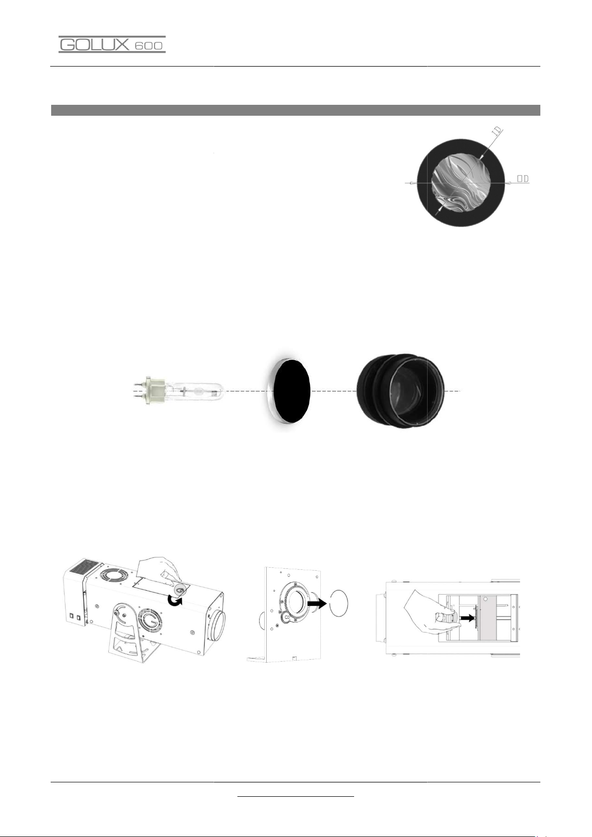
10. LAMP - Carefully read the "operating instructions" provided by the lamp
manufacturer. In order to know the supplied lamp please refer to the section
PACKAGE CONTENT of this manual. Immediately replace the lamp if it is
damaged or deformed by heat.
11. RISK OF VIEW – Never look at the beam of the projector directly or without
optical instruments which convergence the light
12. RESIDUAL RISK – Even if the product is built accordingto all rules and
precautions, residual risks related to certain structural aspects of product usage
could remain. Please, do not disassemble the device. Maintenance should be
performed by personal trainer. Do not tamper for any reason the ballast which
is sealed for safety reasons and should remain so. If ballast is tampered, this
represents a serious danger and in this status the product is no more under
warranty. Set the unit in visible areas and pay attention that does not interfere
with where people are circulating, the risk of a collision must be minimized if is
not possible to eliminate. Do not put the unit in positions where it can fall
or be
hitted by people or animals. Keep children away from the unit when it is
working and it is still connected to the main supply. In case of abnormalities of
the case or breakage of the packaging that contains bright spare parts, do not
turn on the projector and stop the use of the product. Do notinstall in

GOLUX600 - 7 -
ENGLISH
areasavailable
to minors
or persons who should be affected b
y the correct or
wrong use of the product. The device, if it is not connected to main supply, is
not dangerous for people and animals even if exposed to the rain. The
projector works with electrical energy at low voltage and that puts it in an area
of dangerousness typical of a household appliance; it must be considered, in
any case, a lighting box and, therefore, must be adopted during use an
appropriate attitude. The device is designed and constructed using all safety
criteria and suitable materials to prevent hazards and to minimize risks.
2.
PACKAGE CONTENT
When the product is received , please, check that the product if it is in the perfect condition in all its
parts; otherwise contact the manufacturer immediately Take out parts from the package and check if
they have any damage caused by transport The package should be disposed following your country’s
regulations regarding the differentiated waste collection and disposal.
- N°1 ProjectorGOLUX600
- N°1 Pendrivethat contains Manual Instructions and Warranty.
- N°1 Lamp 575W (Philips MSR GOLD 1000 MINIFASTFIT 1CT/4).

- 8 - WWW.GOBOSERVICE.COM
3.
PROJECTOR INSTALLATION
3.1. FRONT SIDE VIEW OF PROJECTOR
The Fig.1 shows the front panel of projector.
ELEMENT 1 is an OUTPUT (POWER ACCESSORIES) at
12V to use when some external accessories are
needed.
ELEMENTS 2 are a pair of holes which are used
when the support bracket for external accessories is
needed.
ELEMENT 3is a quality lens camera.
Fig.1
3.2. BACK SIDE VIEW OF PROJECTOR
Fig.2 shows the
rear panel of the projector
.
ELEMENT 1 is the plug for the power supply cable.
ELEMENT 2 is the switch that controls the power
supply of the projector.
ELEMENT 3is a switch that can enable / disable the
power supply of the internal accessories (gobo
rotation, rotation dynamic effect, etc.).
ELEMENT 4 is a control panel of the main functions
of the projectors.
Fig.2

GOLUX600 - 9 -
ENGLISH
3.3. LENS MOUNTING or SUBSTITUTION
Fig. 3
For the lamp mounting/substitution is needed to act on
the panel that is located at the back side of the main part
of the projector.
Provide yourself with a cloth in order to mount the lamp
in a proper and functional way.
The steps to follow are:
1. Unscrew the knob of the power of the body
mounting plate to the main body of the projector as
shown in Fig.3, the power to rotate on the hinge
body.
2. Remove the three screws that anchor the holder
cover as shown in Figure 4.
3. Turn the lamp counter-clockwise Fig.5 (handling it
with the cloth of which there was previously fitted).
4. Remove the lamp and then replace it with the new
inserting it into the slot interlocking.
5. Replace the body cap lamp through the three screws
removed earlier.
6. Anchor again, using the appropriate knob body the
power to the main body
ATTENTION: Please pay attention that the panel that is
located at the top of the projector is closed before switch
on the projector (the lamp gives off rays that damage the
eyes).
The lamp mounting/substitution must be done when the
projector is switched off and not connected to the mains
supply.
If the lamp must be substituted after the projector usage,
wait (about 15 minutes) so that all internal components of
projector are cool.
Fig. 4
Fig.5

- 10 -
3.4. GOBO MOUNTING
INSTRUCTIONS
The gobo has two main parameters that
projector; these parameters (in Fig.7) are:
l’OD (Outer Diameter) that is the physical gobo diameter;
l’ID (Inner Diameter) , the diameter of the circle that contains the
image to realize.
For GOLUX1000 Projector the gobos must have :
= 35mm. In the case of gobo with special graphics features contact
customer service Goboservice (info@goboservice.com) that will point
you in the best configuration.
ATTENTION: During gobo installation /substitution into the
that the REFLECTING SIDE ALWAYS FACING TOWARDS THE LAMP; on contrary THE MATTED
(BLACK/GREY) SIDE MUST FACE TOWARDS THE PROJECTOR LENS (Fig.8). This mounting rule allows the
correct usage of gobo avoiding its b
LAMPADA
Once you understand the direction of the assembly, open the top cover of the projector turning counter
clockwise the locking hook (Fig. 9); remove the spring clip from the gobo support (see Figure 10); insert
gobo inside the seat making sure it is well bonded to the substrate (Fig 11); then reinsert the support of
the spring clip and then close the top cover of the projector by turning clockwise.
Fig.9
WWW.GOBOSERVICE.COM
INSTRUCTIONS
The gobo has two main parameters that
allow its mounting on
projector; these parameters (in Fig.7) are:
l’OD (Outer Diameter) that is the physical gobo diameter;
l’ID (Inner Diameter) , the diameter of the circle that contains the
For GOLUX1000 Projector the gobos must have :
OD = 37,5mm and ID
= 35mm. In the case of gobo with special graphics features contact
ATTENTION: During gobo installation /substitution into the
projector it is necessary placing the gobo so
that the REFLECTING SIDE ALWAYS FACING TOWARDS THE LAMP; on contrary THE MATTED
(BLACK/GREY) SIDE MUST FACE TOWARDS THE PROJECTOR LENS (Fig.8). This mounting rule allows the
correct usage of gobo avoiding its b
reaking.
GOBO
OBIETTIVO
Fig.
8
Once you understand the direction of the assembly, open the top cover of the projector turning counter
clockwise the locking hook (Fig. 9); remove the spring clip from the gobo support (see Figure 10); insert
gobo inside the seat making sure it is well bonded to the substrate (Fig 11); then reinsert the support of
the spring clip and then close the top cover of the projector by turning clockwise.
Fig.10
Fig.11
Fig.
7
projector it is necessary placing the gobo so
that the REFLECTING SIDE ALWAYS FACING TOWARDS THE LAMP; on contrary THE MATTED
(BLACK/GREY) SIDE MUST FACE TOWARDS THE PROJECTOR LENS (Fig.8). This mounting rule allows the
OBIETTIVO
Once you understand the direction of the assembly, open the top cover of the projector turning counter
clockwise the locking hook (Fig. 9); remove the spring clip from the gobo support (see Figure 10); insert
gobo inside the seat making sure it is well bonded to the substrate (Fig 11); then reinsert the support of
Fig.11

GOLUX600 - 11 -
ENGLISH
ATTENTION: gobo mounting has to be done taking care that the gobo surface will be not touched,
fouled or stained in order to avoid scratches visible on projection; these scratches then, with the heat of
projector usage, can also cause the gobo breaking.
The gobo mounting/substitution must be done when the projector is switched off and not connected to
the mains supply. If the gobo must be substituted after the projector usage, wait (about 15 minutes) so
that all internal components of projector are cool.GOLUX600 EFFECT / GOLUX600 Z EFFECT
Fig.14
3.5.
PUT IN FUNCTION DYNAMIC EFFECT
In GOLUX600 EFFECT / GOLUX600 Z EFFECT
the Dynamic Effect
accessory is installed in replacement of rotating drive holder.
The accessory is formed by two distinct parts:
1. Component 1 (Fig.12) is the mechanical part of the
accessory, which makes it possible to move the effect.
2. Component 2 (Fig.13) is the Effect W
heel, the type of
chosen effect (eg snow effect, musical note effect, etc.)
Having component 1 already installed and setted inside the projector,
we see how to mount component 2:
1. Open the cover at the top of the projector by
unscrewing the locking hook (Fig.9)
2. Place component 2 on component 1 so that the metal
wheel washer stays over the flat and magnetic part of
the pulley, then you have to put the pin inside the
washer.
3. Make sure that the component 2 is firmly seated and
then you can close the top cover of the projector.
If you need to install the Dynamic Effect Accessory inside the projector,
before proceeding to the procedure described above, you will need to
mount component 1 to it, using the holes provided at the base of the
angle (Fig.14) .
CAUTION: During these operations, it is recommended to use a glove
and be particularly careful to handle the wheel, as fragile piece of
equipment.
Fig.12
Fig.13

- 12 - WWW.GOBOSERVICE.COM
3.6. ACCESSORIES POWER SUPPLY
If rather than the GOBO HOLDER other internal accessories that need power
supply have to be used, it is important verify that their power supply plug is
connected to one of the two power connection points available inside the
projector and shown in Fig.15. In particular by using the lower pin of the
accessory, power is continuous while using the plug top , power supply can
be started / suspended by the switch on the rear panel of the projector.
Fig.
15
4.
USE OF PROJECTOR
4.1.
CONNECTION OF PROJECTOR TO THE MAIN SUPPLY
The projector must be connected to the mains supply using the supplied cable. During the connection of
projector to the main supply must be followed the standard safety and operating procedures valid for
any device that operates at low voltage.
ATTENTION: the power supply must be (230V-50/60Hz) and the main supply must have efficient
ground and must be protected by using appropriately sized residual current device with this main
electrical features:
- Rated current In = 20 A
- Differential current IΔn = 0,03A
When the unit is connected to the mains supply must be avoided the contact with water or other liquids.
4.2. PROJECTOR ORIENTATION
The projector GOLUX60
0 can be tilted either
upwards or downwards; in order to direct the
projector it is enough loosen, on both side, the
two special bolts (see Figure 16), put the
projector in the desired direction and tighten the
bolts again.
Fig.16

GOLUX600 - 13 -
ENGLISH
CAUTION: Never turn the projector down so that
it moves in contact with the support surface. (see
Fig.17)
Always refer to the minimum distance from
illuminated objects (5m).
If necessary, you can use the "Extensible Stand"
accessory.
Fig.17
4.3.
SIZING AND FOCUSING THE PROJECTED
The focus of the image must be done by acting on
the kit of zoom lenses installed on the projector
(Fig 18); managing the position of the targets, after
they have been loosened from the respective
knobs. The objectives are moving on a rail through
the use of trolleys
For the versions without the kit of the zoom, the
focus adjustment takes place in almost similar way,
only difference is given by the number of knobs
located on the bottom of the projector, in this case
we shall have only one. Here, too, once the knob is
loose enough to move on the rail the inner
camera until the image does not take a clear look
at this point tighten the knob again.
Fig.18

- 14 - WWW.GOBOSERVICE.COM
4.4. CONTROL PANEL
The GOLUX600
projector is equipped with a control panel that allows you
to access a number of functions, including the main ones:
• Operating time of the ballast
• Time and number of lamp strikes
• Voltage, current and instantaneous power of the lamp
• Temperatures
• Management DMX Address
• Switching on and off the lamp
These functions can be managed by the following keys:
MENU e BACK DOWN
ENTER UP
TIME
Life Time
H.tot
Total Hours ballast
M.tot
Total minutes ballast
H. LAM
Total Hours lamp
M.LAM
Total minutes lamp
Acc. L
Number of power
Lamp
CL.L.V.
Reset (life and
power lamp)
Y.CLr
Confirm reset
push C.MEM*
during 1 second
to confirm
Mon.b.
Monitoring
ballast
P. out
Rated Power
xxxx
Power value
snapshot
r.xxx
Change in val.
nominal
V.out
Rated Tension
xxxx
Voltage value
snapshot
Fig.1
9

GOLUX600 - 15 -
ENGLISH
I. out
Current nominal
xxxx
Current value
snapshot
I. out
Corrente
nominale
t.PFC
Temperature PFC
xxxx
Instantaneous
value
Temperature
PFC
M.P.xx
MaxTemperature
PFC
t.dCd
Temperature DC/DC
xxxx
Instantaneous
value
Temperature
DC/DC
M.d.xx
MaxTemperature
DC/DC
Id.dr
Display and
Exchange Remote ID
Selezione
N° Identification
PushENTER
To confirm
Ad.dM
Change Address
DMX
Address
Selection DMX
Push ENTER
To confirm
LAMP
L.off
Turning Off lamp
Push ENTER
To confirm
L.on
Turning on lamp
Push ENTER
To confirm
VErS
xx.xx
Software Version
The ballast may operate with the signal DMX.
For the management needs 4 channels:
- CH1: ON/OFF 000-128 Lamp On
129-255 Lamp Off
- CH2: DIMMER 000-004 No Effect
005-255 Dimmer from the maximum power at minimum
- CH3: STROBO 000-004 No Effect
005-255 Strobo da 6,5Hz a 35Hz
- CH4: FADE 000-004 No Effect
005-255 Fade time da 13s a 120ms
The Addressed DMX changes from menù Ad.dM → A.xxx

- 16 - WWW.GOBOSERVICE.COM
5.
THECNICAL DATA
DIMENSION
&
WEIGHT
Length 74 cm
Width
21,5
cm
Height
35,5
cm
Weight
15
kg
STRUCTURAL DATA
M
aterial
Alluminio
F
inishing
Opaca
C
olour
Nero
POWER
Voltage
220/240 Vac
-
50/60 Hz
Power
800
W
L
AMP
T
ype
OSRAM HSR 575 W/72
Power
575
W
Brightness
49
.000 lm
Temperature of the
colour
7.2
00 °K
D
uration
100
0 h
PHOTOMETRIC DATA
Projector lightness
24
.
0
00 lm
Dimension
gobo
OD: 37,5
mm
ID:
35,0
mm
P
ossible optical
56mm/100mm/Zoom 7,70°
-
34°
OPTIONAL ACCESSORIES
Gobo holder with rotation
Dynamic effect
Kit change Image
5 Gobo [OD:43,2mm
–
ID:35,0mm]
Shaper
Stand extensible
Stirrup
Palo, Muro
Rain cover

6.
POSSIBLE PROBLEMS CAUSES AND SOLUTIONS
A
BNORMALITIES
The projector does not turn on
The projector turns on but does not emit any
light beam
Reduced brightness
Attack the projector jumps off the breaker
line
Defective projection
The projector beam emits flicker
In the case where the anomaly does not fall in the above cases, contact a technician
7.
DIRECTIVES
The products to which this manual refers are in compliance with
European Community Directives to which they are subject:
-
Low Voltage
-
Electromagnetic compatibility
-
Photobiological
Test carrying out is evidenced by the CE marking on the product and the
declaration of conformity.
8.
DISPOSAL
The
projector must be disposed of in compliance with the applicable laws relating to
lighting products. In any case should not be put in normal waste or litter the
environment; this action even if prosecuted is a serious threat to animals and people
and a sour
ce of pollution in the long term. The product may not be treated as a
simple urban waste and must be disposed of properly according to the regulations in
force concerning the differentiated waste disposal.
GOLUX600
POSSIBLE PROBLEMS CAUSES AND SOLUTIONS
POSSIBLE CAUSES
CONTROL AND SOLUTIONS
No
power
Ensure that the power supply is present
Lamp exhausted or burned out
Lamp Replacement
Lamp exhaustion,
Accidental displacement of the reflector, dirt
of the optical elements,
loss optimal calibration lamp
Lamp replacement, calibration of the
reflector-
lamp system, thorough cleaning of
the optical elements or contact customer
Magneto-line under dimensioned compared
to the characteristics of the projector
Bypass or replace the breaker line
Break of gobo or parable.
Dust or dirt deposits
Attachment defective lamp on the socket
Remove and replace the lamp checking
shooing issued by the complete fitting..
In the case where the anomaly does not fall in the above cases, contact a technician
The products to which this manual refers are in compliance with
European Community Directives to which they are subject:
Low Voltage
.
Electromagnetic compatibility
.
Photobiological
Security.
Test carrying out is evidenced by the CE marking on the product and the
declaration of conformity.
projector must be disposed of in compliance with the applicable laws relating to
lighting products. In any case should not be put in normal waste or litter the
environment; this action even if prosecuted is a serious threat to animals and people
ce of pollution in the long term. The product may not be treated as a
simple urban waste and must be disposed of properly according to the regulations in
force concerning the differentiated waste disposal.
- 17 -
ENGLISH
CONTROL AND SOLUTIONS
Ensure that the power supply is present
Lamp Replacement
Lamp replacement, calibration of the
lamp system, thorough cleaning of
the optical elements or contact customer
service
Bypass or replace the breaker line
Technical consult,
gobo cleaning
Remove and replace the lamp checking
shooing issued by the complete fitting..
In the case where the anomaly does not fall in the above cases, contact a technician
.
The products to which this manual refers are in compliance with
the
Test carrying out is evidenced by the CE marking on the product and the
projector must be disposed of in compliance with the applicable laws relating to
lighting products. In any case should not be put in normal waste or litter the
environment; this action even if prosecuted is a serious threat to animals and people
ce of pollution in the long term. The product may not be treated as a
simple urban waste and must be disposed of properly according to the regulations in

- 18 - WWW.GOBOSERVICE.COM
9.
WARRANTY
The product is warranted under the terms of the law. In case of malfunction during the warranty period,
the product will be repaired or replaced according to manufacturer evaluation.
For further information, refer to the terms of warranty on the CD-ROM.
For the use of the warranty are essential the following information:
- The date of purchase (the invoice date applies).
- Detailed description of the problem.
The unit is sent to you in perfect condition. It is important to follow the safety instructions and warnings
contained in this manual. Any damage caused by failure of the manual will void the warranty. The
manufacturer assumes no responsibility for damage or problems caused by failure of the manual.
Any repairs should be done by the manufacturer, which declines any responsibility for unauthorized
access. Dismantling (including partial) of projector that is not made by the manufacturer will void the
warranty.
Consumables (such as lamp and fuse) are not covered by the warranty.
Manufacturer reserves the right to modify the content of this manual at any time and without notice.

GOLUX600 - 19 -
ENGLISH
10.
MAINTENANCE HISTORY
Projector
Mod
.:
Date of purchase
:
Serial Number
:
Date of first power on
:
LAMP SUBSTITUTION
DATE
BRAND
MODEL
LIFE
SUPPLIED ACCESSORIES

- 20 - WWW.GOBOSERVICE.COM
NOTE
Table of contents
Other Goboservice Dj Equipment manuals
Popular Dj Equipment manuals by other brands

Velleman
Velleman SPACE ROLLER 150 manual

TourPro Lighting
TourPro Lighting AQUABEAM SERIES user manual

SIGNIFY
SIGNIFY Strand AURORA LED STRIP 4 CELL user manual

5Star Systems
5Star Systems Spica 250M user manual

Equinox Systems
Equinox Systems PRO DJ Booth Quad-colour Starcloth user manual

Show Tec
Show Tec POWERBOX 3 manual