(Hz)
<MODE>
1,
<MULTI>
2
,,
,10,5Hz,2
,1010,
1510,,
,15
●
●
● 1/11/2
● "buLb”
● --,,,
3
● <SET>,
● <SET>,
● <SET>,
1/4
1/8
1/16
1/32
1/64
1/128
1/256
1
7
20
30
60
90
100
100
2
6
15
30
60
90
100
100
3
5
12
30
60
90
100
100
4
4
10
20
50
80
100
100
5
3
8
20
50
80
100
100
6-7
3
6
20
40
70
90
90
8-9
3
5
10
30
60
80
80
Hz 10
2
4
8
20
50
70
70
11
2
4
8
20
40
70
70
12-14
2
4
8
20
40
60
60
15-19
2
4
8
18
35
50
50
20-50
2
4
8
16
30
40
40
60-100
2
4
8
12
20
40
40
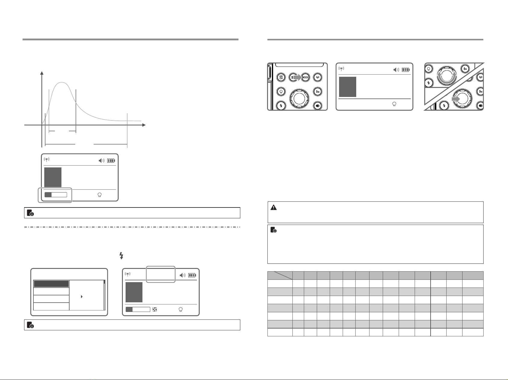
Multi:
/
M:
t=0.5
,t=0.1t=0.5t=0.1
M
±75KMENU C.Fn-COLOR,ON
M
M
CH 1 M
A
10%
1/128
t.1 1/8690
CH 1 MCOLOR
A
10%
1/256
t.1 1/6410
C.Fn
SLAVE
MODEL
STANDBY
OFF
ON
Ver0.6
COLOR
CH 1 Multi
A
OFF
1/256
5 - 5 Hz
A
t
50%
10%
t=0.5
t=0.1
- 15 - - 16 -