GOETTL Evaporative Coolers Manual

®
Installation & Operating Instructions
For
Goettl Evaporative Coolers
Manufactured By
GOETTL AIR CONDITIONING, INC.
P.O. Box 52029, Phoenix, Arizona 85072-2029

INSTALLATION
1. Before you start, read all of the instructions.
.
3.
Installationsmay require that you adapt these instructionsto special requirements.
On receiving your cooler, check for concealed shipping damage, and note any damage on the
freight bill. Such damage is the responsibilityof the freight carder, and any claims must be
filed with them. Unpack the unit carefully, being sure that accessories and instructionsare not
discarded with the packing material.
ROOF MOUNTED UNITS
Step 1:
Select location of cooler and roof opening as determined by requirements of ductwork, roof
construction and cooler appearance.
Cut the roof opening. Do not cut any structural members without approval of your architect,
builder, or authorized persons having jurisdiction. Follow their instructions. If approval is
received to cut joists or roof rafters, it is suggested they be'headed as shownin figure la.
Where the rafter or joist must be left in place it shouldbe capped both top and bottomto de-
flect air flow, as shown in figure 1b. Note that leaving such framing in the ductcan cut down
cooler air delivery as much as 10%.
Fig. la. Cut and framed roof
opening for cooler installation. Figure lb. Capped rafter orjoist.
-2-

Step 2:
Construct an angle iron or wood platformto provide a level mounting surface for the cooler.
Typical roof platforms are shown in Figure 2 for down discharge coolers and Figure 3 for
horizontal discharge coolers.
Measure cooler, or find size from catalog to determine size of platform. Platform must be
located.so cooler discharge opening will line up with duct work. On a pitched roofthe open
sides of the platform frame may be covered with galvanized sheet steel or other weatherproof
material. An opening or removable panel must be left in one side, large enough for access for
the drain fitting in the cooler bottom. For down discharge coolers the duct shouldbe fastened
to the platform collar before setting cooler in place. The duct should have astandingflange
over which the cooler discharge opening willfit.
Flash and seal around the duct. Figures 2 and 3 show flashing and rain shield to provide
weather tightness with flexibility.
WALL MOUNTED HORIZONTAL DISCHARGE UNITS
Step 1.
Determine location of cooler, and of opening in the building wall, depending on duct work and
building arrangement.
Check with your architect or builder before cutting any structural member.
Approval received, cut the wall opening frame, as shown in Figure 4. Any stud which must be
cut should be headed and the opening framed as shown.
Figure2. Construction of roof platform
for down discharge coolers, t _""_
jl .
horizontal discharge coolers, ing for wall mounted, horizontal
tdischarge cooler installation.
-3-

step 2.
Construct a platform, either from the ground or fastened to the buildingwall, to provide a level
mountingsurface for the cooler. A typical mounting platform is shown in Figure 5. Measure
cooler orflnd size from catalog to determine size of platform and position of duct opening in
wall.
It is usually easiest to install main duct inthe attic space before liftingthe cooler intoplace.
Flash and seal around the duct so the entire entry is weathertight.
ALL UNITS
Step 3.
Mount the cooler on the platform. For large coolers, sign and riggingcompanies are often
available to liftthe unit into place. Large coolers are of bolted construction and can be disas-
sembled and taken up in pieces if necessary.
The unit should be sealed and isolated from the platform and from the duct flange with sponge
rubberor plastic seal strips. Figures 6 and 7 show typical completed installations. Anchor
linesfrom top of cooler to roof may be necessary in areas withvery highwinds.
/
Figure 5. Typical waft-type platform
for evaporative cooler. Figure6. Typicalinstallation of roof-
mounted down discharge unit.
Figure 7. Typical completed installationof
waftmounted horizontal discharge unit. -4-

Step 4,
Connect 1/4" O.D. water tubing to cold water supply, Either an adapter faucet or a saddle
valve can be used for connection to the water supply line.
Connect electrical conduit to junction box assembly located in corner of cooler top.
EleIctrical knock outs are provided on the corner post for electrical connection convenience.
Refer to wiring diagrams (located within the manual) for proper connections. All wiring
must be done in accordance with all local codes. All units must be grounded in accordance
to all code requirements.
Step 5.
Each unit contains a heavy duty constructed motor cradle. Each cradle is secured to the
motor mounting bracket. Mount motor in motor cradle and secure with motor clamps
provided in the bag assembly. Attach motor sheave and align belt.
Adjust belt tension by sliding motor cradle. Belt tension should be set until belt can easily
be deflected 1/2 to 3/4 of an inch. Secure motor cradle into position by tightening four bolts.
Step 6.
Connect duct work as required and install room grilles or discharge vents. For simple
installations a duct equal in size to the cooler discharge opening will be satisfactory. Grilles
should have four-way adjustable vanes for air flow direction.
Step 7.
Make the final adjustment on cooler according to the following check list:
1. Be sure duct work is complete, all dampers are open and all grilles are wide open.
Check electrical input to unit for correct voltage.
2. Turn on electrical power supply. Check blower and pump motors to be sure both are
operating freely. ._
/") -.
Figure 8. Combination duct and direct
type cooling is often used in multi-unit
commercial installations.
-5-

3. Check current draw of blower motor. A tong type ammeter is usually the most
convenient method of m_asuring. Be sure motor current is not greater than name plate
full load rating at the supply voltage used. If motor current is too high, the motor pulley
can be adjusted to slow the blower wheel. Turning the free half counter-clockwise
(decreasing pitch diameter) will decrease blower speed and air delivery, and decrease
motor amperes. Turning clockwise will increase blower speed and increase motor
amperes. The pulley must not be opened so far as to allow the belt to ride on the hub,
since this will cause rapid wear. The locking set screw should only be tightened down
on the flat provided. Tightening down on the threads will make the pulley difficult to
adjust at any later time.
Motor adjusting bolts must be moved to compensate for tighter or looser belt,
depending on which way the pulley was adjusted. Set belt tension so that moderate
hand pressure will depress belt at center point between pulleys approximately 1 inch.
Remember that too-loose belts cause belt slippage, wear and noise, while too-tight belts
cause excessive bearing wear.
Refer to Figure 1.
Step 8.
Turn on water. Check float valve operation, and adjust to provide correct water depth in
cooler bottom. Water should be 2 1/2 inches deep. "
Step 9.
Check for equal water flow from all distributor tubes. If water flow is too great, reduce by
closing pinch fitting on pump discharge tube. Then check water flow from water trough in
louver troughs.
Step 10.
After entire s
rooms as re_ uired for comfort.
i 2
"
i i
=i
tstem is operating, adjust dampers and grille louvers to provide air in various
1. Motor clamps
2. Motor
3. Motor pulley
4. Motor cradle
5. Adjustment bolts
6. Motor mount
4
-6-
6
.:\ (Fig. 1)

SERVICE
UNIT MAINTENANCE
WATER CONTROL: Coolers are controlledmanually by linevalve. Turn valve on untilwater
flows freely from all water distributortubes and in sufficientquantity to thoroughlysoak pads.
Before turning on motor, let water run a few minutes to remove dust from pads and prevent
delivery of untreated air.
ADJUSTABLE MOTOR PULLEY: Adjustable motor pulleys are set at the factory for maxi-
mum motor load and maximum air delivery of cooler not connected to a duct and register
system. When cooler is connected to a duct system, the cooler air capacity and motor amper-
age decreases due to static pressure duct resistance. The adjustable motor pulley is used
ONLY to compensate for duct system resistance by returning cooler and motor to maximum
load capacity and should not be adjusted except for this purpose.
CAUTION: When it is necessary to adjust pulley, AMPERAGE OF MOTOR MUST BE
CHECKED TO MAKE CERTAIN IT DOES NOT EXCEED THE MAXIMUM ALLOWED AS
STAMPED ON MOTOR SPECIFICATION PLATE. Only person with properelectrical equip-
ment and thorough knowledge of adjustable pulleys'should attempt adjustment of motor pulley
on your cooler.
IMPROPER PULLEY ADJUSTMENT COULD OVERLOAD AND BURN OUT MOTOR.
BELT ADJUSTMENT: Correct belt tension and alignment is important as it cuts power con-
sumption and prolongs life of belt and motor. When installing or adjusting belt, loosen the
four motor mount bolts and adjust until belt can be easily deflected 1/2 to 3/4 of an inch.
DO NOT TIGHTEN BELT BY ADJUSTING MOTOR PULLEY. Align belt vertically by
centering motor pulley in-line with blower pulley. Re-tighten the four motor mount bolts.
-,_r
m\
t_
AIR EXHAUSTING: Windows or doors at a point most distant from cooler air inlet shouldbe
left open to permit free movement of air out of area being cooled, and avoid building up static
pressure. Proper location of exhaust openings is important as they guide flow of air through
areas where cooling is desired. -7-

UNIT MAINTENANCE (CONT.)
!
WATER CONTROL: The overflow standpipe screwed into drain bushing forms a water reser-
voir of the cooler bottom. The floating valve regulates water supply intocooler reservoir. The
depth of water is regulated by loosening the float adjustment screw and raisingor lowering
float untilwater level remains approximately 2 1/2 deep. If manual valve is present in water
supply line, open valve and allow to remain open during the cooling season. Water flow
to cooler pads isfurnished bythe recirculating pump, and the desired amount of water is regu-
lated bythe water check clamp located on pump hose between pump and water distributor.
BLEED OFF A'I-rACHMENT KIT: A small, pinpoint amount of =used"water is bled off ordis-
carded whenever the pump is in use. This keeps the water fresh and free from mineral con-
centrations.
CLEANING: The cooler cabinet and recirculating pump should be periodically inspected,
cleaned and all scratches or bare metal should be covered with suitable protective paint. To
prevent excessive deposits of water minerals and sediment, the reservoir pan should be
cleaned at least every sixty days of operation. When a recirculating pump is used, remove
overflow standpipe from drain fitting and allow water to drain, thoroughly clean pump and
components making sure that impeller is free before cooler operation. Replace standpipe and
fill reservoir. Operate cooler 15 minutes, then allow all water to drain through, thus cleaning
entire system, always drain water reservoir completely when cooler is not in use over pro-
longed periods and particularly at end of cooling season.
OILING: All motors and blower shaft bearings are oiled at the factory, butshould be checked
before operating cooler. If need for oiling is indicated, use any good grade S.A.E. No. 20 or 30
oil. Apply 2 or 3 drops of oil to each oil cup on cooler motor and pump motor. The oil cups on
blower shaft bearings should be filled. Under normal use, oiling is required every three months
of operation.
THE SLIDING DAMPER: (Optional) On the blower, housing should be closed in the fall to
keep cold air from entering the building. For pre-season cleaning, with the damper still
closed, the blades of the blower are accessible for cleaning through the opening in the
blower housing, this makes it possible to keep debris from entering the home.
IMPORTANT: Before operating cooler at the beginning of each cooling season, turn blower
wheel, cooler motor and pump motor shafts by hand to make sure they turn freely. Failure to
do this may result in burning out motor.
FILTER PADS: Filter pads should be replaced with fresh aspen fiber excelsior and DUSTRAP
filterat least once a year, at the beginning of each cooling season. The need for changing
pads mor_ ff_quently varies with localityand rapidity with which dirt, alkali, and o.th0rforeign
matter accumulates in pads. If cooling efficiency is impaired, it may be desirable to change
pads several times during cooling season.
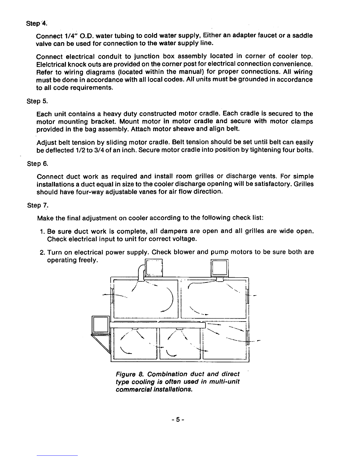
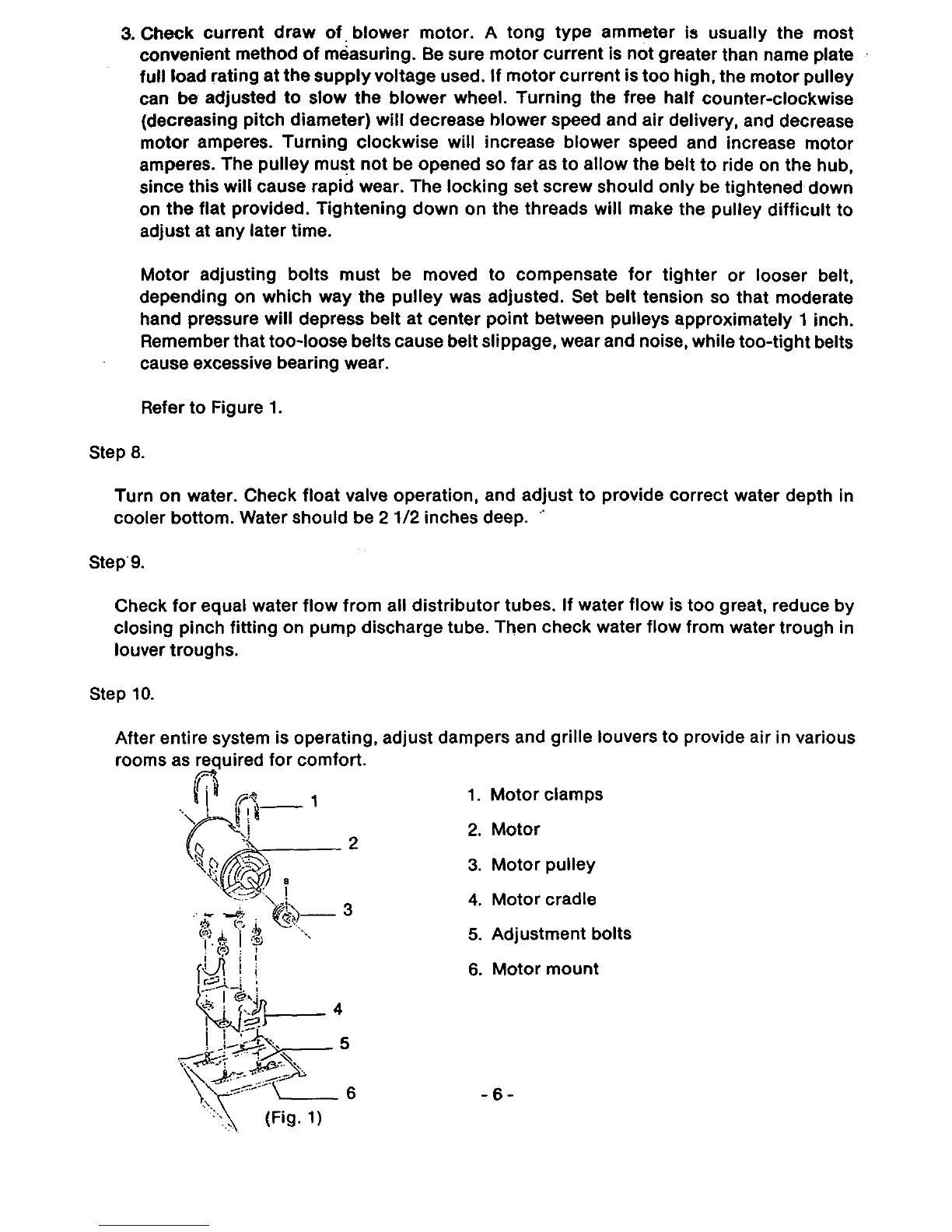
-8-

PAD REPLACEMENT:
1. With Iouvered panel lying on flat surface, wire retainer face up, grasp retainer in center
and pull upward, thus bowing retainer, at the same time pulling out ends of wire from
underneath flange of Iouvered panel.
2. Clean Iouvered panels, if necessary.
3. Replace pad with new material, being sure pad is of uniform thickness, without voids,
which permit untreated air to enter the cooling system.
4. Replace wire pad retainer and reverse steps to complete pad replacement in same
manner as removal.
MOTOR REPLACEMENT:
The motor can easily be replaced by removing plug from junction box and removing motor
clamps.
CAUTION:
DISCONNECT ALL ELECTRICAL POWER SOURCE PRIOR TO PERFORMING ANY
MAINTENANCE ON UNIT.
Remove louver panels using lower handles. Do not remove panels by inserting hands into
open louver sections.
Replace motor and motor cord, and secure motor with clamps. Secure motor sheave and
connect motor plug to junction box receptacle. Turn on power and check amp draw on
motor. Adjust motor sheave as necessary (Ref. Page 7). Turn off power and secure louver
panels. Turn on power.
-9-

TROUBLESHOOTING
Here is a listingof some common service problems, with probable causes and suggested
remedies:
PROBLEM
Inadequate
Cooling:
PROBABLECAUSE SUGGESTED REMEDIES
Cooler undersized Replace with larger cooler
Clogged or dirtyfilters Replace with pads
Dry pads or lack of water Check water distributing
while cooler isoperating system for possible obstruction
in tubing. Check pump.
Insufficientair discharge
openings or inadequate
exhaust from area being
cooled, causing humidity
building up and discomfort.
Make sure there is adequate
provisionfor exhausting air from
area being cooled.
Excessive humidity.
(See also item above
re: inadequate exhaust)
In some areas, there may be a few
days during the summer when the
relative humidity is high, resulting in
complaints about poor cooling. The
limitations of an evaporative cooler
under conditions of high wet bulb
temperature should be explained to
the customer.
Blower turningbackwards Reconnect motorfor correct direction
Blower installedbackward Remove and reinstallblower wheel
to turn in correct direction
Blower runningtoo slow Check motor amps. If below name
plate amperage, readjust variable
pitch motor pulley to increase blower
speed,
Belt slipping or ... -._
wearing excessively: Belt loose.
Moisture getting on belt.
Adjust belt
Check for loose water connections
Pulleys outof line Align pulleys
-10-

PROBLEU PROBABLECAUSE
Belt slippingor
wearing excessively
(cont.):
Blower fails
to start:
:SUGGESTED REMEDY
Worn belts Replace belts
Worn or imperfect pulleys Replace pulleys
No fuse or fuse blown Replace fuse
Loose electrical Check all electrical connections
Connections
Defective switch Replace switch
Motor burned out Replace motor
Belt or pulley loose Check belts or pulleys
Belt broken or missing Install new belt
Belt too tight Check belt tension
Improper adjustment of
variable pitch motor pulley
causing motoroverload
Motor overheats
or burns out:
Pump fails
to operate:
Check variable pitch motorpulley
for proper adjustment. A variable
pitch motor pulley can be adjusted to
accommodate the speed of the
blower to the ductwork used. Adjust
pulley so motor amperes do not
exceed fullload amperes shown on
motor name plate,
Low voltage Check voltage and consultwith
power company if voltage is low
Incorrect power supply Check power supply against motor
name plate specifications
Incorrectmotor, motor has Be sure motor iscorrect size for
been changed cooler
Pump motorfailure Replace complete pump
Improper wiring of pump Recheck pump leads connected
leads to motor and switch to power and switch.
Loose electrical Check electrical connections
connections
Pump switchfaulty Replace pump switch
-11 -

PROBLEM
Pump runs but
does notcirculate
water, pump runs
but pads lack water:
Cooler noisy:
Continuous over-
flow ofwater:
Water being thrown
into room:
PROBABLE CAUSE
Insufficientwater in
bottom of cooler pan
SUGGESTED REMEDY
Check float adjustment, water should
be maintained at approximately
2 1/2" depth.
Pump screen plugged Clean screen
Clogged tubing Clean the tubing
Foreign matter lodged in Remove pump hose from the tee
the water distributingtee and clean out foreign matter
Wheel rubbing on housing Re-position wheel
Wheel out of balance due Check wheel and clean
to dirt, etc:
Cooler delivering more air Adjust motor pulley to slow down
than needed blower
Improper alignment of Loosen blower bearings and realign
blower bearings
Improper adjustment of Adjustblower shaft, set collars snug
blower shaft set collars but not too tight
Belt "squealing" Tighten bell by adjusting motor.
Apply bell dressing to belt. In some
cases it may be necessary to replace
bell
Float valve adjustment
incorrect
Valve stuck open because
of lime deposits
Loose Dist. tubing or pump
hose connections
Adjust float valve
Clean valve and adjust
Check and tighten all tubing and
hose connections
Break in copper tubing or Replace any cracked or I_rol_en
pump hose tubing or hose
Cover not installed on float Install cover on float valve to prevent
valve to prevent spray spray
Pads not properly installed
in holders and have
sagged -12-
Make sure filtersareproperly
installed in holders, which prevent
sagging filters.

PROBLEM
Water being
thrown into
room, (cont):
Foam or suds
Rapid formation
of white deposits
on pads and
louvers:
Dust and alkali
pullingoff pads:
PROBABLECAUSE SUGGESTED REMEDIES
Discharge ends of water
distributiontube do notfit
intothe water distributing
troughs in top of pad
frames
Make sure water distribution tubing
discharges water into water
distribution troughs in top of pad
frames
Old pads that have Replace with new pads
developed thin spots
Pump delivering excessive
water to filters Install hose clamps on hose to
restrict supply of water.
When filter pads are
installed where the water
is relatively soft, if the wood
has a higher than normal
amount of saponin, the
pump may churn up suds
f
Algae in sump water
Drain and refill cooler sump with
fresh water. May need to be
repeated for severe cases
Drain cooler bottomand clean
thoroughly, fillwithfresh water.
Install new pads
Filters remain wet after
shut down Allow blower to run for about 10
minutes after pump is shut off to dry
off pads
Water level too high.
Keeps lower edge of filter
always wet
Re-adjust water level so filters are
above water in cooler bottom
High mineral content of
supply water
Install drain connections from cooler
with a shut-off valve in a convenient
location. Instruct user to open valve
about once a week to flush out all
the water in the cooler. Frequency of
flushing will vary depending on hard-
ness of water supply and amount of
usage of the cooler. Adjust bleed off.
m
Pads dry when cooler Turn pump on about 10 minutes
started up before blower isturned on
-13-

BASIC WIRING DIAGRAMS
MOTOR
BLACK
IiRED
_1_ WHITE
REC. PUMP Q
JUNCTION SWITCH ] 115 VOLT
i__ 115 V. LINE
TSW_TCH POWER LINE
JUNCTION
REC. PUMP O
BLACK
I','_ _, _ RED E_
MOTOR _WHITE
ii
SWITCH I115 VOLT
115 V. LINE
POWER LINE
\ GREEN GROUND
JUNCTION AUTO SWITCH
RELAY BOX
_'_ YELLOW _ BLK. V. LINE
MOTOR |LOO |RED iO c
___ WHITE LOO
/.j_.%_ WHITE
REC. I [°'i
PUMPI k_" GREEN
ol 11__5
I
PWR. LINE
GROUND
i
CAUTION: Always make sure unit is properly grounded in accordance with National Bectric Code.
Do not connect pump wire to Hi and Low terminals.
Important -- Improper wiring will void warranty.
-14-
Table of contents
Other GOETTL Air Conditioner manuals
Popular Air Conditioner manuals by other brands

EINHELL
EINHELL MKA 2001M operating instructions

Rinnai
Rinnai CJ Series Wi-Fi Operation Manual

LG
LG JW-Q24WUXA owner's manual

Bryant
Bryant SINGLEPACKAGED AIR CONDITIONER 564A User's information manual

Olimpia splendid
Olimpia splendid UNICO EASY S1 Instructions for use and maintenance

Haier
Haier HSU-09LH13 installation manual