USER’S MANUAL
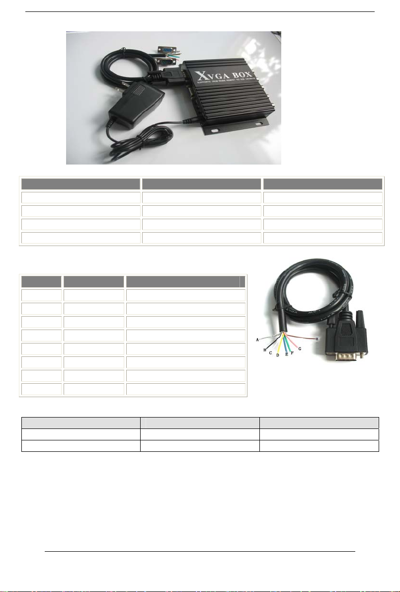
BNC Input Signal Connection image
Pb、Y、Pr YPbPr input signal (right image)
Interface: three BNC slot, connected
to the corresponding Pb, Y, Pr
interface, then Y monochrome port.
Figure 4.2 Analog 3BNC (YPBPR) Input.
R、G、B RGB Sog input signal (right image)
Interface: three BNC slot, connected
to the corresponding R, G, B slot,
then G monochrome port.
Figure 4.3 Analog 3BNC (RGB Sog) Input.
R、G、B、S RGBS CS Composite Sync (right
image)
Interfaces: 4 BNC slot, connected to
the corresponding R, G, B, S I,
monochrome then G, S I
Figure 4.4 Analog 4BNC (RGBS CS) Input.
R、G、B、H、V RGBHV separate sync (right image)
Interface: 5 BNC slot, connected to
the corresponding R, G, B, H, V I,
monochrome then G, H, V I
Figure 4.4 Analog 4BNC (RGBS CS) Input
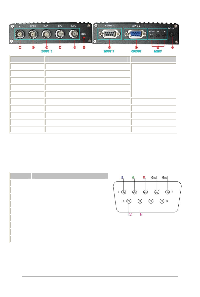
5. Operation Menu
Figure 5.1 MENU
Item Spec.
①MENU -press it to enter into OSD menu
-click it once to select and click
again to exit the current line
②“+”-click it to move the cursor up
-click it to add the value for
certain item
③“-“-click it to move the cursor down
-click it to deduct the value for
certain item
User’sManual -4-