Gonnheimer Elektronic F870S User manual

User's manua
l
Pressurized
enclosure system
F870S
Manual_F870S_v1.0.2_2016.doc

F870S Inhalt Page 2
Gönnheimer Elektronic GmbH Tel.: +49 (6321) 49919-0 Fax: +49 (6321) 49919-41
Content
1Operation instruction for Explosion protected device............................................................................ 4
2Introduction: Pressurized enclosure system F870S.............................................................................. 5
2.1 Explosion protection: pressurized enclosure ................................................................................. 5
2.2 Pressurized enclosure according to EN 60079.............................................................................. 5
2.3 Pressurized enclosure system F870S ........................................................................................... 6
2.3.1 Simultaneous PID- control of cabinet pressure and flow rate ................................................ 6
2.3.2 Enlarged, free programmable range of operation................................................................... 7
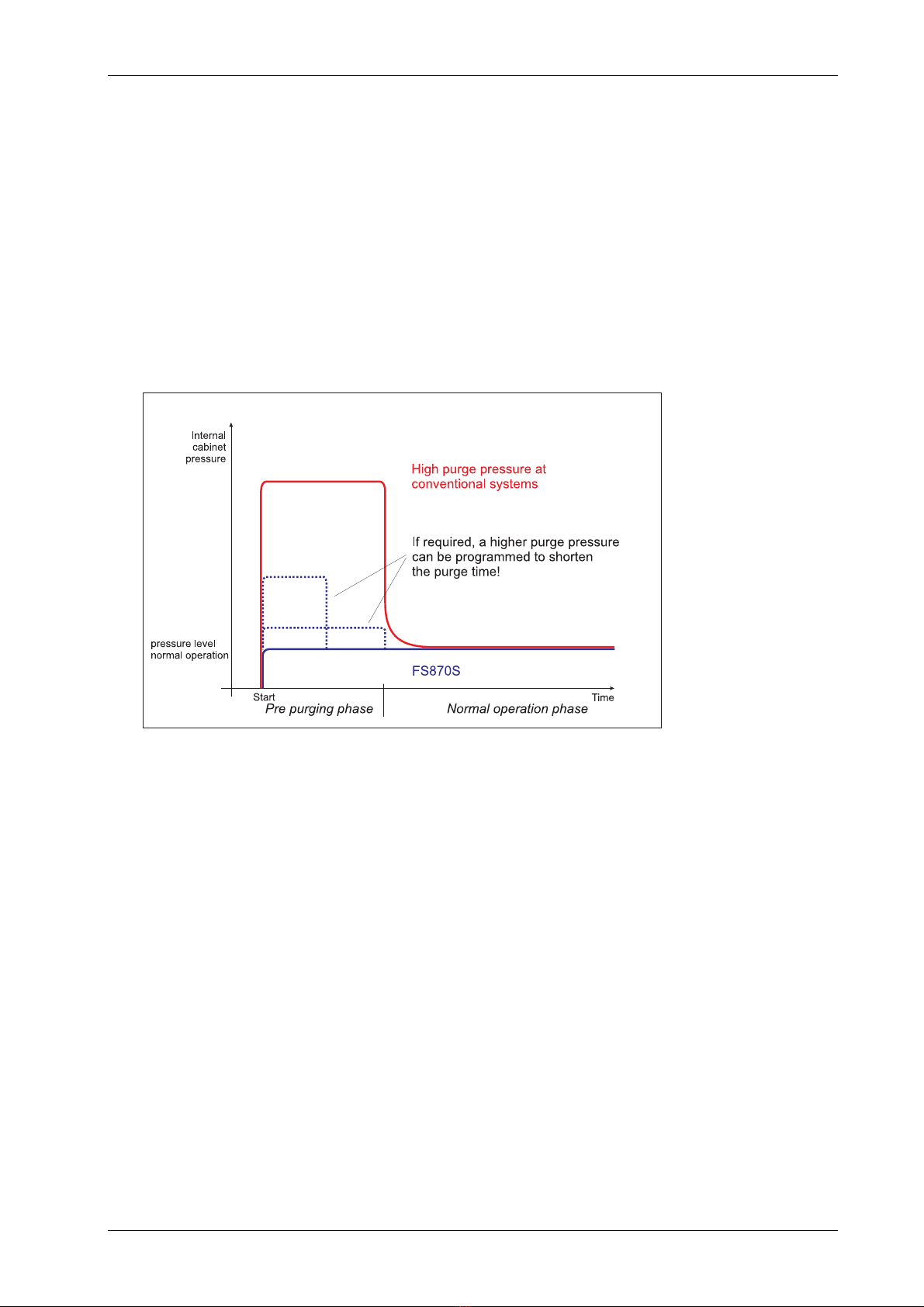
2.3.3 Lowered cabinet stressing due to smaller pressure and pressure gradients ......................... 8
2.4 Components of pressurized enclosure system F870S .................................................................. 8
2.4.4 Leakage compensation........................................................................................................... 9
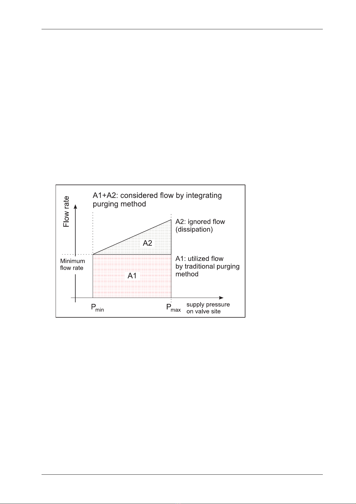
2.4.5 Continuous flow .................................................................................................................... 10
2.4.6 F870S - Application using „Containment Systems “............................................................. 10
2.5 Peripherals ................................................................................................................................... 11
2.5.1 Ex i- external sensory: ES872 .............................................................................................. 11
2.5.2 Configuration module: CM873.............................................................................................. 11
2.5.3 Operating panels .................................................................................................................. 11
2.5.4 Common operating panels: BT 854.1 and BT 855.1 ............................................................ 11
2.5.5 Intelligent operating panel type BT871 ................................................................................. 11
2.5.6 Disconnector unit SR852 and power relay SR853 ............................................................... 11
2.6 Features in operation zone 21 (Dust) .......................................................................................... 12
2.6.1 Purging period -> cleaning period: cleaning the housing inside........................................... 12
2.6.2 Additional marking ................................................................................................................ 12
2.7 Additional information: EC- type certificate F850-SYST.............................................................. 12
2.8 Conformity with standards ........................................................................................................... 12
3Installation and Connection................................................................................................................. 13
3.1 Mounting ...................................................................................................................................... 13
3.1.3 Control unit FS870S ............................................................................................................. 13
3.1.4 Particle barrier....................................................................................................................... 13
3.1.5 Proportional solenoid valve................................................................................................... 13
3.1.6 Operator panels BT8xx.x ...................................................................................................... 13
3.1.7 Disconnector unit SR852 and power relay SR853 ............................................................... 14
3.2 Connecting and Commissioning .................................................................................................. 14
3.2.1 Connection hints ................................................................................................................... 15
3.2.2 Switching power off ability .................................................................................................... 15
3.2.3 Intrinsically safe (Ex i-) connection of FS870S..................................................................... 16
3.2.4 Connections FS870S of protection class (Ex e) ................................................................... 16
3.2.5 Default parameter ................................................................................................................. 17
3.2.6 Ex works parameter – Reset ................................................................................................ 18
3.3 Maintenance................................................................................................................................. 18
3.4 Repairs......................................................................................................................................... 18
4Operation............................................................................................................................................. 19
4.1 Human interface........................................................................................................................... 19
4.1.1 Display .................................................................................................................................. 19
4.1.2 Joystick ................................................................................................................................. 19
4.1.3 Log file (show Log) ............................................................................................................... 19
4.1.4 How to enter and leave the bypass mode ............................................................................ 20
4.2 Parameter input and parameter query......................................................................................... 21
4.2.1 Operation menu .................................................................................................................... 21
4.2.2 Parameter input menu .......................................................................................................... 21
4.2.3 Menu exposition.................................................................................................................... 22
4.3 Alarm and malfunction indications ............................................................................................... 23
4.3.4 Alert....................................................................................................................................... 23
4.3.5 Error messages..................................................................................................................... 23
5Annex .................................................................................................................................................. 24
5.1 Technical Details.......................................................................................................................... 24
5.1.6 Pneumatic data..................................................................................................................... 24
5.2 Type codes................................................................................................................................... 25
5.3 Marking ........................................................................................................................................ 26

F870S Inhalt Page 3
Gönnheimer Elektronic GmbH Tel.: +49 (6321) 49919-0 Fax: +49 (6321) 49919-41
5.4 Dimensions .................................................................................................................................. 27
5.5 Mounting examples...................................................................................................................... 29
5.6 Flow diagram................................................................................................................................ 29
5.7 Block diagram .............................................................................................................................. 30
5.8 Transport, Storing, Disposal and Repairs.................................................................................... 31
5.9 Sequence of operation diagram................................................................................................... 32
5.10 List of Parameters .................................................................................................................... 33
The symbols WARNING, CAUTION, NOTE
This symbol warns of a serious hazard. Failure to observe this warning may
result in death or the destruction of property.
This symbol warns of a possible failure. Failure to observe this caution may
result in the total failure of the device or the system or plant to which it is
connected.
This symbol highlights important information.
Safety Measures: to read and to comply
Warning! Extreme caution is advised when handling this device. High
electrical discharge is possible and can be fatal.
Work on electrical installations and apparatus in operation is generally forbidden in
hazardous locations, with the exception of intrinsically safe circuits. In special cases
work can be done on non-intrinsically safe circuits, on the condition that during the
duration of such work no explosive atmosphere exists.
Only explosion protected certified measuring instruments may be used to ensure
that the apparatus is voltage-free. Grounding and short-circuiting may only be car-
ried out, if there is no explosion hazard at the grounding or short circuit connection.
Danger of static charge!
Clean only with humid cloth!
Do not open when an explosive dust atmosphere is present!

F870S 1 Operation instruction for explosion protected device Page 4
Gönnheimer Elektronic GmbH Tel.: +49 (6321) 49919-0 Fax: +49 (6321) 49919-41
1 Operation instruction for Explosion protected device
Application and Standards
This instruction manual applies to explosion-protected devices of types below. This apparatus is
only to be used as defined and meets requirements of EN 60 079 particularly EN60 079-14
"electrical apparatus for potentiality explosive atmospheres".
Use this manual in hazardous locations, which are hazardous due to gases and vapors accord-
ing to the explosion group and temperature class as stipulated on the type label. When installing
and operating the explosion protected distribution and control panels you should observe the
respective nationally valid regulations and requirements.
General Instructions
Work on electrical installations and apparatus in operation is generally forbidden in hazardous
locations, with the exception of intrinsically safe circuits. In special cases work can be done on
non-intrinsically safe circuits, on the condition that during the duration of such work no explosive
atmosphere exists.
Only explosion protected certified measuring instruments may be used to ensure that the appa-
ratus is voltage-free. Grounding and short-circuiting may only be carried out, if there is no ex-
plosion hazard at the grounding or short circuit connection.
To achieve an impeccable and safety device operation, please take care for adept transporta-
tion, storage and mounting, as well as accurate service and maintenance. Operation of this de-
vice should only be implemented by authorized persons and in strict accordance with local safe-
ty standards.
The electrical data on the type label and if applicable, the "special conditions" of the test certifi-
cate BVS 10 ATEX E 112are to be observed.
For outdoor installation it is recommended to protect the explosion protected distribution and
control panel against direct climatic influence, e.g. with a protective roof. The maximum ambient
temperature is 40°C, if not stipulated otherwise.
Terminal compartment in Increased Safety
When closing, it is to be ensured that the gaskets of the terminal compartment remain effective,
thus maintaining degree of protection IP 54 according to EN 60529. Close unused entries by
impact-proof stopping plugs, which are secured against self-loosening and turning.
Do not open the device in Ex area, as long the device is energized.
Inside area with explosive dust do clean the inner of the housing of the dust before closing the
housing.
Maintenance Work
The gaskets of Ex e enclosures are to be checked for damages and replaced, if required. Ter-
minals, especially in the Ex e chamber are to be tightened. Possible changes in color point to
increased temperature. Cable glands, stopping plugs and flanges are to be tested for tightness
and secure fitting.
Intrinsically Safe Circuits
Erection instructions in the testing certificates of intrinsically safe apparatus are to be observed.
The electrical safety values stipulated on the type label must not be exceeded in the intrinsically
safe circuit. When interconnecting intrinsically safe circuits it is to be tested, whether a voltage
and/or current addition occurs. The intrinsic safety of interconnected circuits is to be ensured.
(EN 60079-14, section 12)

F870S 2 Pressurized enclosure system F870S Page 5
Gönnheimer Elektronic GmbH Tel.: +49 (6321) 49919-0 Fax: +49 (6321) 49919-41
2 Introduction: Pressurized enclosure system F870S
2.1 Explosion protection: pressurized enclosure
The use of pressurized enclosures allows the operation of ‘non explosion protected’ devices
in hazardous areas inside zone 1 and zone 2. The protection type ‘pressurization’ is based
on the principle of maintaining a constant pressure using air or a protective gas to prevent
an explosive mixture forming near the device inside the pressurized enclosure.
Before start-up, the pressurized enclosure must be purged with air or protective gas to re-
move any explosive mixture that may be inside the enclosure.
2.2 Pressurized enclosure according to EN 60079
Since the second issue of the standard EN 50016 (May, 1996) control devices for the pro-
tection type "pressurized enclosure" are classified as security related devices.
At that time, the notified bodies, (PTB, EXAM, TUEV NORD, etc.) declared that an ex p-
control device must fulfill the category 3 of EN 954-1. This concept was taken over also in
the standards EN 60079 ff.
After the replacement of EN 954-1 by the standards IEC / EN 61508-1 and -2, respectively
EN ISO DIN 13849-1 and -2 and DIN EN 50495 a security level of at least SIL 2 is required
for a pressurized enclosure control unit according to EN 60079-2. This is a valid arrange-
ment between the German notified bodies.
Figure 1: Performance levels
The pressurized enclosure system F870S reaches performance level „d“ according to
EN 13849 and therefore it reaches SIL Level 2 according to IEC / EN 61508.

F870S 2 Pressurized enclosure system F870S Page 6
Gönnheimer Elektronic GmbH Tel.: +49 (6321) 49919-0 Fax: +49 (6321) 49919-41
2.3 Pressurized enclosure system F870S
2.3.1 Simultaneous PID- control of cabinet pressure and flow rate
Based on the first introduction of proportional valve technology within pressurized enclosure
systems (patented system Gönnheimer F850) an additional active proportional valve was
integrated to the F870S in the outlet.
Figure 2: block diagram simultaneous pressure and flow control
This concept permits simultaneous PID-regulation of cabinet pressure and flow rate and
generates new solutions and possibilities for pressurized enclosure systems and attach-
ments.

F870S 2 Pressurized enclosure system F870S Page 7
Gönnheimer Elektronic GmbH Tel.: +49 (6321) 49919-0 Fax: +49 (6321) 49919-41
2.3.2 Enlarged, free programmable range of operation
In comparison to common Ex p control systems, the FS870S offers an increased and free
programmable range of operation (characteristic pressure / flow curve).
The conventional systems are characterized by a fixed pressure / flow curve (see e.g.
FS850S) with an offset, caused by the opening pressure of the passive mechanical outlet
valve. This typical opening pressure (2... 4 mbar at standard systems) is required to mini-
mize the system leakage rate during normal operation.
Fixed curves by control
devices with flow meas-
urement with plate orifice
Figure 3: Range of operation
The input and output sided PID-control loops allow the FS870S to perform in the whole
range of operation (see figure 2).

F870S 2 Pressurized enclosure system F870S Page 8
Gönnheimer Elektronic GmbH Tel.: +49 (6321) 49919-0 Fax: +49 (6321) 49919-41
2.3.3 Lowered cabinet stressing due to smaller pressure and pressure gradients
During the purging phase a high flow rate should be achieved to shorten the purge time.
Based on their construction, conventional Ex p- systems show only a smooth rising of the
flow rate while increasing the cabinet pressure.
In this aspect, the FS870S with its reduced flow restriction and back pressure is superior to
any conventional Ex p system.
Within midrange flow rates, the load to the Ex p- cabinet walls is up to four times lower in
comparison to conventional systems!
2.4 Components of pressurized enclosure system F870S
The pressurized enclosure system F870S contains at least the control unit FS870S and a
solenoid valve. Each can be mounted in- or outside the enclosure. Furthermore several re-
mote controls (operation panels) are available to improve ease of operation. It is also pos-
sible to connect intrinsically safe sensors to the control unit FS870S.
The pressurized enclosure system F870S has two basic operation modes:
•Pressurization using leakage compensation
•Pressurization using continuous flow of protective gas.

F870S 2 Pressurized enclosure system F870S Page 9
Gönnheimer Elektronic GmbH Tel.: +49 (6321) 49919-0 Fax: +49 (6321) 49919-41
2.4.4 Leakage compensation
Within this operation mode the unit generate and hold a pressure level of at lest 0.8 mbar
(80 Pa) inside the Ex p- cabinet.
The use of a proportional solenoid valve prevents wasting of the purge medium while the
pre purging procedure as well later in basic operation mode.
In tradition to the control unit GÖNNHEIMER FS850S, the first Ex p- control unit using pro-
portionally working pressure and flow control, the FS870S works as well as an input-sided
pressure regulator:
The proportional solenoid valve is the actuator of a PID- control and regulates the incoming
purge medium accordingly to the leakage of the cabinet. The benefits of pressure feedback
control are:
1. Considerable less consumption of protective gas - additional costs for proportional valve will
be amortized soon
2. Increased service reliability achieved by constant pressure inside enclosure - increasing leak-
age caused by e.g. ageing of the enclosure will be balanced and sudden failure is pre vented
3. Almost no flow noise and only a small protective gas consumption using a solid enclosure
Figure 4: Consumption of protective gas
Another advantage using a proportional solenoid valve is; that pressure control is also used
during purging. A set-point pressure will be achieved in the enclosure, while the flow vol-
ume, that leaves the enclosure, will be recorded and integrated over time, until the required
purge volume is achieved. The advantages are:
1. A defined pressure while purging - pressure sensitive parts of the enclosure, like mem-
brane switch panels or windows, will not be overloaded.
2. Purge volume accuracy is achieved by integration of the purge medium flow volume at
the outlet. Wasting purge medium is no more a topic of today.
The use of the F870S system leads to a considerable stress relief of the Ex p cabinet and
sensitive parts like foil keyboards, windows etc.. In comparison to conventional Ex p- sys-
tems, the FS870S requires a much lower cabinet pressure to achieve a comparable flow
rate. (Example: A reduction of the cabinet pressure by 5 mbar leads to 50 kg / m² de-
creased load at the cabinet walls).

F870S 2 Pressurized enclosure system F870S Page 10
Gönnheimer Elektronic GmbH Tel.: +49 (6321) 49919-0 Fax: +49 (6321) 49919-41
2.4.5 Continuous flow
The control unit FS 850S incorporates the operation mode „continuous flow“. This operation
mode is necessary, for example if an analyzer produces an explosive atmosphere inside
the enclosure (containment system). The operation mode continuous flow flushes the en-
closure permanently. After the (pre-) purging procedure (purging process) a set-point flow
rate is adjusted during normal operation. A flow rate minimum will be monitored also.
This system design allows a simultaneous PID- control of cabinet pressure and flow rate
and opens new possibilities within the construction of pressurized enclosure systems and
applications.
In operation mode "continuous flow" the FS870S is capable to lower the flow rate from a
high value during purging to a low value during normal operation at a constant, low cabinet
pressure level. (Example: 3 liters/sec. to 0.3 liters/sec. decrease without pressure variation)
Figure 5: time diagram
2.4.6 F870S - Application using „Containment Systems “
„Containment Systems“ are defined as parts of a device within a pressurized enclosure,
which could emit combustible gas (or occasionally an explosive environment: zone 1, ex-
plosive mixture) from within the enclosure.
In order to receive an Ex p-System including a „Containment System“, which is failsafe ac-
cording EN 60079-2, with the attribute 'no emission', the following conditions must be met:
1. The flammable substance inside the containment system is in the gas or vapor phase
when operating between the specified temperature limits
2. The minimum pressure specified for pressurized enclosure is at least 50 Pa higher than
the maximum pressure specified for the containment system
3. An automatic safety device initiates, if the pressure difference falls below 50 Pa.
This automatic safety device can be activated by a difference pressure switch, looped into
the external alarm loop (terminal 5/6 on FS870S). If an alarm occurs on this loop, the con-
trol device FS870S will turn off the ignition-capable device immediately. After alarm cancel-
ing the control device FS870S starts operation automatically with the purging procedure.
The external alarm loop is made by a normaly closed connection method.

F870S 2 Pressurized enclosure system F870S Page 11
Gönnheimer Elektronic GmbH Tel.: +49 (6321) 49919-0 Fax: +49 (6321) 49919-41
2.5 Peripherals
2.5.1 Ex i- external sensory: ES872
The intrinsically safe bus interface is used to transmit measurement values from the exter-
nal proportional sensor module ES872 to the control unit. This allows the integration of ad-
ditional safety control features into the purge control system.
This interface is also suitable for e.g. temperature or other sensors.
2.5.2 Configuration module: CM873
Using the same Ex i- bus, the customer can connect the optional configuration module
CM873 to load application specific configuration data and parameters into the control unit
without further manual programming.
The handling is quite simple: plug this CM873 into the intended port and restart the control
device.
2.5.3 Operating panels
For the control unit FS870S several operating and visualizing panels are available. These
panels consist of the explosion protection class 'intrinsically safe' and are considerably ad-
vantageous, particularly when the control unit is mounted inside the enclosure.
2.5.4 Common operating panels: BT 854.1 and BT 855.1
•On/Off-Switch
•Key-operated switch for bypass
•LED-indicator for READY and ON
The connection to the control unit consists of 6 wires.
2.5.5 Intelligent operating panel type BT871
This operation panel indicates operation and malfunction reports as plain text. The 5 mem-
brane switches offer total command of the control unit. Status, actual pressure, flow rate as
well as remaining purge time are always available.
The connection to the control unit consists of only 4 wires.
Signal lamps on BT871
The BT871 has three colored signal lights (LED). These report system states and warnings.
2.5.6 Disconnector unit SR852 and power relay SR853
According to EN 60079-2 all non- intrinsically safe connections of the ignition capable appa-
ratus must be disconnect, if the protection gas pressure falls below the safety limit. In many
applications more than the two connector terminals on the control unit FS870S are needed.
In these cases the disconnector unit SR852, with 8 respectively 16 galvanically separated
connectors, is considerable helpful.
The power relay S853 provides 4 lines with switching power of 250V, 16 A.

F870S 2 Pressurized enclosure system F870S Page 12
Gönnheimer Elektronic GmbH Tel.: +49 (6321) 49919-0 Fax: +49 (6321) 49919-41
2.6 Features in operation zone 21 (Dust)
2.6.1 Purging period -> cleaning period: cleaning the housing inside
In zone 21 the housing must not be purged in comparison to the operation in gas zone 1.
The operator has to insert the purging volume zero “0 [l]” into the parameter menu.
Purging in the presence of combustible dust would generate a dangerous explosive atmos-
phere inside the cabinet.
In the zone 21 the purging period is replaced by a cleaning period, viz. the operator has to
remove thoroughly the combustible dust inside before he is energizing the electrical parts
inside the cabinet.
After cleaning the pressure inside of the cabinet prevent an infiltration of dust.
2.6.2 Additional marking
The cabinet must contain a well viewable sign with the following content:
„WARNING: REMOVE ALL DUST FROM THE INSIDE OF THE ENCLOSURE BEFORE
CONNECTING OR RESTORING THE ELECTRICAL SUPPLY“
On Ex p cabinets suitable for zone 21, which can be opened without tools, has to be placed
the following mark:
„WARNING: DO NOT OPEN WHILE ENERGIZED UNLESS IT IS OBVIOUS THAT NO
COMBUSTIBLE DUST IS PRESENT“
2.7 Additional information: EC- type certificate F850-SYST
Gönnheimer features as manufacturer of Ex p- Systems a comprehensive ATEX Ex p-
SYSTEM Certification of a notified body.
Provides a economical solution for small quantities
•certified for Ex- Zone 1
•enhanced for Dust- Ex, Zone 21 (category 2D)
•the first ATEX certification of this type in Europe
•matches > 80% of all individual customer systems
•enhanced pressure ranges: 27mbar, 350mbar and 1 bar.
Costumer advantages:
+ usual delivery time, + usual quality,+ usual costs,+ no additional efforts
2.8 Conformity with standards
The explosion proof control unit FS870S meets requirements of listed standards in the at-
tachment (Declaration of conformity). They were developed, manufactured and tested in
accordance with state-of-the-art engineering practice and ISO9001:2008.

F870S 3 Mounting and connection Page 13
Gönnheimer Elektronic GmbH Tel.: +49 (6321) 49919-0 Fax: +49 (6321) 49919-41
3 Installation and Connection
3.1 Mounting
3.1.3 Control unit FS870S
The control unit can be placed inside a hazardous area. The location (inside or outside the
enclosure) as well as the position is almost arbitrary.
The control unit has 4 holes on the rear plate for mounting, although fixing only with the
screw connection of intake or outlet is sufficient.
While mounting observe local safety guidelines and
the regulative DIN EN 60079-14.
The reference input of the device (M5 thread on the
left side) should be in the ex area.
If the device is mounted inside the Ex p- housing, the reference input
must be connect to the ambient by a pipe connection.
The solenoid valve(s) and the control unit (respec-
tively pressure monitor) should be mounted on the
enclosure as far away from each other as possible
(E.g. space diagonal arrangement), to achieve a total
purging.
3.1.4 Particle barrier
The control device contains a particle barrier according to EN 60079-2. Therefore it is al-
lowed to exhaust the purge medium direct onto the ex area.
3.1.5 Proportional solenoid valve
The proportional working solenoid valve (SVP…) should be mounted outside of the Ex p
cabinet. The mounting direction is arbitrary.
3.1.6 Operator panels BT8xx.x
°Operator panel BT871.0
The operating tableau BT871.0 (without rear) becomes directly mounted outside on the Ex
p- cabinet. Therefore 5 drillings must be made into the cabinet. Please refer the drilling
scheme in the appendix.
°Operator panel BT871.5
The operator panel BT871.5 contents a complete housing in protection class IP65. It could
be mounted arbitrary in hazardous area Zone 1. Please refer the dimension scheme in the
appendix for the position and diameter of drillings.
°Operator panel BT854.x
The BT854.0 consists of 2 signal lamps and an On/Off switch which are directly attached to
the Ex p- cabinet. For the BT 854.1 a key switch to active bypass mode is added. Please
refer the dimension scheme in the appendix for the position and diameter of drillings.
°Operator panel BT855.x

F870S 3 Mounting and connection Page 14
Gönnheimer Elektronic GmbH Tel.: +49 (6321) 49919-0 Fax: +49 (6321) 49919-41
The operating tableau BT855.x has got a complete housing (protection class IP65). It can
be mounted in the ex-area of Zone 1 at any place. Please refer the dimension scheme in
the appendix for the position and diameter of drillings.
3.1.7 Disconnector unit SR852 and power relay SR853
The disconnector unit SR852 and power relay SR853 could be placed in hazardous area
Zone 1. These are certified on its own in protection type Ex e.
3.2 Connecting and Commissioning
22212019
NL
36
37
34
35
24 2623 25 27 28 29 30 31 32 33
Relay1 Relay2 Alarm
-
+
38
PE
PE
Ventilsicherung/
F solenoid valve)use (
Magnetventil/
Solenoidvalve
40
41
39
42 Ethernet
24135796810
--+++++---
ext.
Alarm
Bypass ON OK
LED ON
LED
Ex i
12 1614 1811 1 513 17
ext. Druck/
pressure
BT871
BT871Ext. Sen.
Netz/
Mains
Kontakte für Spannungsfreischaltung
Cu t-o ff - co nta cts
FS870S
43
44
-+
TX+
RX-
TX-
RX+
nb.
nb.
Figure 6: electrical block diagram

F870S 3 Mounting and connection Page 15
Gönnheimer Elektronic GmbH Tel.: +49 (6321) 49919-0 Fax: +49 (6321) 49919-41
3.2.1 Connection hints
Conditions for the Ex e clamps
Min. and max. clamping torque min. 0,3 Nm
max. 0,4 Nm
Min. und Max. wire cross- section steep: 0,2 – 2,5 mm²
flexible: 0,2 – 2,5 mm²
Consider the following items while connecting und starting
LINE VOLTAGE!
Extreme caution is advised when handling this de-
vice. High electrical discharge is possible and can
be fatal.
Please note the following Standard of Compliance:
BVS 10 ATEX E 112, IECEx BVS 10.0095 and the
regulative DIN EN 60079-14.
Do not exceed terminal safety limits of each termi-
nal.
See limits in technical details or declarations of conformity.
The breaking current of the built-in valve fuse must
correspond to the used solenoid valve
3.2.2 Switching power off ability
The maximum current limits (5 A) on the clamps 28,
29 and 30, 31 should not be exceeded at any time!
E.G. By an application of switched power supply a multiple higher cur-
rent as the nominal max. current may occur. In this case a switching on
current limitation (e.g., NTC) must be added to avoid the off-limits high
current.
If this is missed the risk of welded relay contacts and within the loss of
the explosion protection exists!!

F870S 3 Mounting and connection Page 16
Gönnheimer Elektronic GmbH Tel.: +49 (6321) 49919-0 Fax: +49 (6321) 49919-41
3.2.3 Intrinsically safe (Ex i-) connection of FS870S
Clamps Description Limits
1,2 Digital input: Bypass U0 I0 P0 C0 L0
5,4V 6,2mA 8,3mW 100nF 0,5mH
3,4 Digital input: On / Off U0 I0 P0 C0 L0
5,4V 6,2mA 8,3mW 100nF 0,5mH
5,6 Digital input:: External alarm U0 I0 P0 C0 L0
5,4V 6,2mA 8,3mW 100nF 0,5mH
7 (+)
8 (-)
LED- output: “System On” U0 I0 P0 C0 L0
5,4V 9,7mA 13mW 100nF 0,5mH
9 (+)
10 (-)
LED- output: “System Ready” U0 I0 P0 C0 L0
5,4V 9,7mA 13mW 100nF 0,5mH
Clamps Description correspondences
11-14 External
Pressure/temperature sensor: ES872
Ext. configuration module: CM873
11 (FS870S) – 1 (ext. device)
12 - 2
13 - 3
14 - 4
15-18 Port BT871
15 (FS870S) – 1 (BT871)
16 - 2
17 - 3
18 - 4
3.2.4 Connections FS870S of protection class (Ex e)
Clamps Description
19, 20 (N -) Line voltage, either neutral conductor at AC or minus pole at DC
21, 22 (L +) Line voltage, either outer conductor at AC or plus pole at DC
23 up to 27 Potential earth, PE
28, 29 Working current circuit 1 (Relays 1),
Um = 253V, Im = 5A, cos (ϕ) = 0,7
30, 31 Working current circuit 2 (Relays 2),
Um = 253V, Im = 5A, cos (ϕ) = 0,7
32, 33 signal pressure alarm (Alarm), Um = 253V, Im = 5A
34, 35 Terminals for solenoid valve fuse inside device
36 (-),
37 (+)
38 (PE)
Output solenoid valve: 24V DC, connect the valve here
39 (TX-)
40 (TX+)
41 (RX-)
42 (RX+)
43 (nb.)
44 (nb.)
ETHERNET 10/100Mbit Um = 63V AC/DC
The claps 43-44 serve for the connection the not used ETHERNET wires

F870S 3 Mounting and connection Page 17
Gönnheimer Elektronic GmbH Tel.: +49 (6321) 49919-0 Fax: +49 (6321) 49919-41
3.2.5 Default parameter
Parameter defaults ex works.
Description Display Settings Unit
Structure Language setting of FS870S Language English
Do you use a proportional (SVP..) or
digital (SVD…) working valve Valve SVP3
Operation mode:
- Leakage compensation
- Continuous flow Operation mode Leakage compen-
sation
Function of the free programmable alarm
contact Output function Bypass is active
Contact order
Normally closed (NC)
Normally open (NO) NC/NO NO
The external alarm loop is programmable
to work in special situation only Ext-Alert mode Inactive
External sensor ES872 is connected to
the system or not ES872 connected No
Parameter Purge volume Purge volume 500 Ltr.
Set point of pressure controller while pre
purging phase Setpoint Pres.Purge 2.0 mbar
Monitored minimum flow while pre
purging phase Min.Flow Purge 0,5 Ltr./s
Set point of flow controller while pre
purging phase Setpoint-Flow Purge 2,0 Ltr./s
Set point of pressure controller while
normal operation (after pre purging
phase) Setpoint - Pres.Oper 2,0 mbar
Monitored minimum pressure inside Ex p
housing - at all times Min. Pressure 0,8 mbar
Monitored maximum pressure inside Ex
p housing - at all times Max. Pressure 15,0 mbar
Pressure limit of alarm pressure Alarm Pressure
Codes Code word main menu Menu code 0001
Code word to activate bypass function Bypass code 0002
Code word to switch on or off the ignition
capable apparatus inside the Ex p
cabinet On/Off code 0001
Network IP-
A
ddress IP-Address 192.168.0.48
Subnet mas
k
Subnet Mask 255.255.255.0
Gateway Gateway 192.168.0.1

F870S 3 Mounting and connection Page 18
Gönnheimer Elektronic GmbH Tel.: +49 (6321) 49919-0 Fax: +49 (6321) 49919-41
3.2.6 Ex works parameter – Reset
Do RESET :
1. Press the joystick* while powering up the device until
“RESET appears on the display.
2. Enter RESET-Code: “1111”
3. Press the joystick
The ex works parameter are now active.
*: only on the control unit, not on the BT871
3.3 Maintenance
Depending upon purity of the assigned purging air the inlet and outlet opening of the
FS870S must regularly be examined on impurities (e.g. oil, dust, etc) or corrosion. In case
of serious impurities the operator should weigh the possibility of a punctual appropriate
cleaning by Gönnheimer Elektronic GmbH in relation to a spontaneous loss of the control-
ler.
3.4 Repairs
Repairs of the controller as well as the accessories may be made only by the Gönnheimer
Elektronic GmbH.

F870S 4 Operation Page 19
Gönnheimer Elektronic GmbH Tel.: +49 (6321) 49919-0 Fax: +49 (6321) 49919-41
4 Operation
The user has total control of the purging system F870S by the use the joystick on the con-
trol unit FS870S respectively by using the external operating panel BT871. Operation on
control unit FS870S panel BT871 is equal. Using the other operating panels only a restrict-
ed operation is possible.
4.1 Human interface
4.1.1 Display
The built-in graphical display indicates operation modes, actual data of pressure or flow
rate, as well as malfunctions.
Beside the status side the user can switch to the info side using the joysticks right move.
Status side Info side
Purging
P = 0,8 mbar, Fl = 4 l/s
Description to Info- side:
Row Description
P = 2,0 mbar Actual pressure inside Ex p cabinet
Q = 3,5 l/s T = 20°C Flow rate through FS870S, air temperature
Valve: 34% aperture rate of the input valve
U = 65V I = 162 mA Voltage and current at input valve (SVP)
Throttle: 0,00 Opening rate of the output valve
Positive values : Throttle opens
Negative values: Throttle gets tighter
4.1.2 Joystick
See process information to your Ex p system using the joystick inside of the FS870S. Con-
firm settings by pressing this joystick.
4.1.3 Log file (show Log)
The FS870S logs every important information of the Ex p system into an internal log file.
The logs get a time stamp. With this information the user gets useful information if some-
thing works unexpected.
The log file is located in the operation menu.
P = 2,0 mbar
Q = 3,5 l/s T = 20°C
Valve: 34%
U = 65V I = 162 mA
Throttle: 0,00

F870S 4 Operation Page 20
Gönnheimer Elektronic GmbH Tel.: +49 (6321) 49919-0 Fax: +49 (6321) 49919-41
4.1.4 How to enter and leave the bypass mode
Utilize bypass only, if it is sure that no explosive atmosphere is
inside the cabinet!
Fire certificate required!
The bypass mode is denied, if it is possible that an explosive at-
mosphere can arise inside the Ex p- housing!
The bypass can be activated with the joystick and the menu in the display as follows:
1. Press joystick 2 x times
2. Move joystick down one time: Select “Bypass”
3. Enter bypass code with the joystick “0002”
4. Change Bypass mode to active “Bypass ON”
5. Confirm the setting by pressing by pressing the joystick
The bypass is active immediately
Leave the bypass mode in the same way as enter.
Table of contents