SAFETY INSTRUCTIONS
7
Cleaning
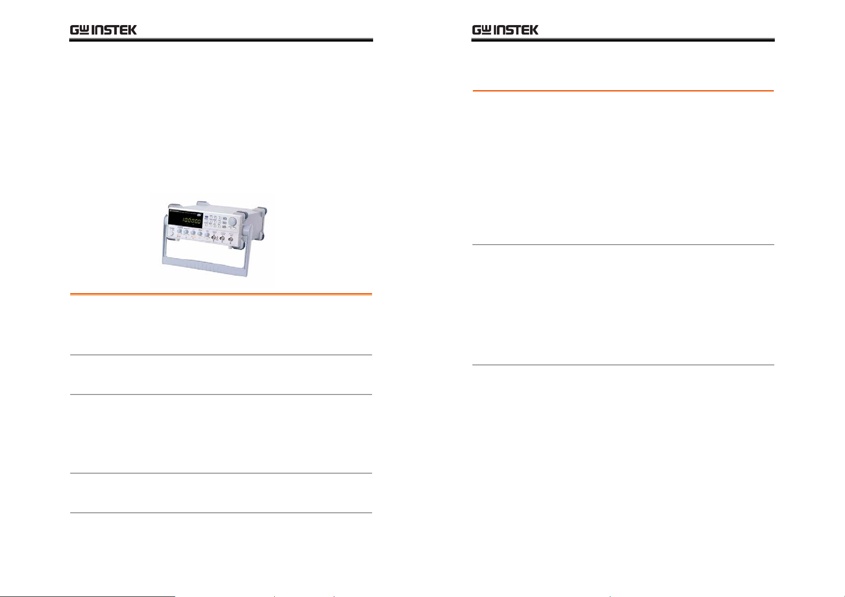
SFG-2000 series
•Disconnect the power cord before cleaning.
•Use a soft cloth dampened in a solution of mild
detergent and water. Do not spray any liquid into
SFG-2000 series.
•Do not use chemicals or cleaners containing harsh
materials such as benzene, toluene, xylene, and
acetone.
•Location: Indoor, no direct sunlight, dust free, almost
non-conductive pollution (Note below)
•Relative Humidity: < 80%
•Altitude: < 2000m
•Temperature: 0°C to 40°C
Operation
Environment
(Note) EN 61010-1:2001 specifies the pollution degrees and their
requirements as follows. SFG-2000 series falls under degree 2.
Pollution refers to “addition of foreign matter, solid, liquid, or
gaseous (ionized gases), that may produce a reduction of dielectric
strength or surface resistivity”.
•Pollution degree 1: No pollution or only dry, non-conductive
pollution occurs. The pollution has no influence.
•Pollution degree 2: Normally only non-conductive pollution
occurs. Occasionally, however, a temporary conductivity caused
by condensation must be expected.
•Pollution degree 3: Conductive pollution occurs, or dry,
non-conductive pollution occurs which becomes conductive due
to condensation which is expected. In such conditions,
equipment is normally protected against exposure to direct
sunlight, precipitation, and full wind pressure, but neither
temperature nor humidity is controlled.
Storage
Environment
•Location: Indoor
•Relative Humidity: < 80%
•Temperature: −10°C to 70°C
SFG-2000 Series User Manual
8
Power cord for the United Kingdom
When using SFG-2000 series in the United Kingdom, make sure the power
cord meets the following safety instructions.
NOTE: This lead / appliance must only be wired by competent persons
WARNING: THIS APPLIANCE MUST BE EARTHED
IMPORTANT: The wires in this lead are coloured in accordance with the following code:
Green/ Yellow: Earth
Blue: Neutral
Brown: Live (Phase)
As the colours of the wires in main leads may not correspond with the colours marking
identified in your plug/appliance, proceed as follows:
The wire which is coloured Green & Yellow must be connected to the Earth terminal
marked with the letter E or by the earth symbol or coloured Green or Green & Yellow.
The wire which is coloured Blue must be connected to the terminal which is marked with
the letter N or coloured Blue or Black.
The wire which is coloured Brown must be connected to the terminal marked with the
letter L or P or coloured Brown or Red.
If in doubt, consult the instructions provided with the equipment or contact the supplier.
This cable/appliance should be protected by a suitably rated and approved HBC mains
fuse: refer to the rating information on the equipment and/or user instructions for details.
As a guide, cable of 0.75mm2 should be protected by a 3A or 5A fuse. Larger conductors
would normally require 13A types, depending on the connection method used.
Any moulded mains connector that requires removal /replacement must be destroyed by
removal of any fuse & fuse carrier and disposed of immediately, as a plug with bared wires
is hazardous if a engaged in live socket. Any re-wiring must be carried out in accordance
with the information detailed on this label.