4
PRODUCT DESIGN NFPA 54/ANSI Z223.1 - latest edition. In Canada, the fur-
nacesmustbeventedinaccordance with theNationalStan-
dard of Canada, CAN/CSA B149.1 and CAN/CSA B149.2
-latesteditionsand amendments.
NOTE: Theverticalheightof the Category I ventingsystem
must be at least as great as the horizontal length of the
ventingsystem.
Accessibility Clearances (Minimum)
Unobstructed front clearance of 24" for servicing is rec-
ommended.
SW B
1036 11
* 24" clearance for serviceability recommended.
MINIMUM CLEARANCE TO COMBUSTIBLE MATERIALS - INCHES
** Single Wall Vent (SW) to be used only as a connector.
Refer to the venting tables outlined in the Installation Manual for
additional venting requirements.
Vent
Sides TopRear Front*
Note: Inall cases accessibility clearanceshall take prece-
dence over clearances from the enclosure where accessi-
bility clearances are greater. All dimensions are given in
inches.
HighAltitudeDerate
IMPORTANT NOTE: The furnace as shipped requires no
change to run between 0 - 4500 feet. Do not attempt to
increase the firing rate by changing orifices or increasing
themanifoldpressurebelow4500feet.Thiscancausepoor
combustionandequipment failure.
Highaltitudeinstallationsabove4500feetmayrequireboth
a pressure switch and an orifice change. These changes
are necessary to compensate for the natural reduction in
the density of both the gas fuel and the combustion air at
higheraltitude.
For installations above 4500 feet, please refer to your dis-
tributorforrequired kit(s). Contact thedistributorfor a tabu-
lar listing of appropriate manufacturer’s kits for propane
gasand/orhighaltitudeinstallations. The indicatedkitsmust
be used to insure safe and proper furnace operation. All
conversions must be performed by a qualified installer, or
service agency.
GeneralOperation
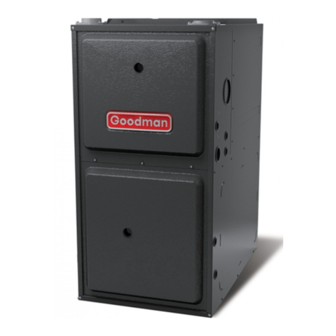
TheGDH8furnacesareequippedwithanelectronicignition
deviceusedtolighttheburnersandaninduceddraftblower
to exhaust combustion products.
An interlock switch prevents furnace operation if the inner
blowerdoor is not inplace. Keep the blower access door in
placeexceptfor inspection and maintenance.(Seeillustra-
tionon page 5.)
This furnace is also equipped with a self-diagnosing elec-
tronic control module. In the event a furnace component is
notoperatingproperly,thecontrolmoduleLED will flashon
and off in a factory-programmed sequence, depending on
theproblemencountered. This light canbeviewed through
theobservationwindowin the blower access door.Referto
theTroubleshootingChartforfurtherexplanationoftheLED
codesandAbnormalOperation-IntegratedIgnitionControl
section in the Service Instructions for an explanation of the
possibleproblem.
Theratedheatingcapacityof the furnace should be greater
thanor equal to thetotal heat lossof the area tobe heated.
The total heat loss should be calculated by an approved
methodorinaccordance with “ASHRAE Guide” or “Manual
J-LoadCalculations”publishedbytheAirConditioning Con-
tractors of America.
*Obtain from: American National Standards Institute 1430
BroadwayNewYork,NY10018
LocationConsiderations
• The furnace should be as centralized as is practical
with respect to the air distribution system.
• Donotinstallthefurnacedirectly on carpeting, tile, or
combustiblematerialotherthanwood flooring.
• When installed in a residential garage, the furnace
mustbepositionedsotheburnersandignition source
are located not less than 18 inches (457 mm) above
the floor and protected from physical damage by ve-
hicles.
Notes:
WARNING
TO PREVENT POSSIBLE PERSONAL INJURY OR DEATH DUE TO ASPHYXIATION,
THIS FURNACE MUST BE CATEGORY IVENTED. DO NOT VENT USING
CATEGORY III VENTING.
CategoryI Venting is ventingat a non-positive pressure. A
furnace vented as Category I is considered a fan-assisted
appliance and the vent system does not have to be “gas
tight.” NOTE: Singlestagegasfurnaceswithinduced draft
blowers draw products of combustion through a heat ex-
changerallowing,in some instances, common venting with
naturaldraftappliances(i.e.waterheaters).All installations
mustbeventedinaccordancewithNationalFuelGasCode
