manuals.online logo
Brands
  1. Home
  2. •
  3. Brands
  4. •
  5. Goodmans
  6. •
  7. Car Receiver
  8. •
  9. Goodmans GCE2814IP User manual

Goodmans GCE2814IP User manual

In Car Radio Compact Disc Player
Model GCE2814IP
MODEMODE
LO/DXLO /DX
MUTEMUTE SEAR CHSEARC H
PT YPT Y
AS/PSAS/PS PAUPAU 1122
INTINT 33
RPTRPT 44RDMRDM BANDBA ND
66
55
TATA
2 ZON E2 ZONE
AFAF
SUB-WSUB-W
DISPDISP
MENUMENU
SELSEL
ENTERENTER
INSTRUCTION
MANUAL
e
13
022706
P. 1
CONTENTS
P. 2
ACCESSORIES...........................................................Page 3
INSTALLATION...........................................................Page 4 - 5
DETACHABLE FRONT PANEL......................................Page 6
WIRING IDENTIFICATION............................................Page 7
PANEL OPEN/ CLOSE OPERATION..............................Page 8
IDENTIFICATION OF CONTROLS AND FUNCTIONS......Page 9
BASIC OPERATIONS...................................................Page 10
MENU OPERATION. .Page 11
DUAL ZONE OPERATION .Page 12
AUDIO OPERATION............................ .......... ..Page 13 - 14
TUNER OPERATION.................................. ......Page 15
RDS OPERATION................................ .............Page 16
CD/MP3/WMA OPERATION............... ...............Page 17 - 20
iPod OPERATION......................... ...................Page 21 - 22
NOTE ON DISCS............................ ...................Page 23
SPECIFICATIONS.......................... .................Page 24
TROUBLE SHOOTING......................... .............Page 25
....................................................
............................................
............ .
............
...........
............
............
...........
.............
............
NOTE
Only Apple I-pod family of products can be connected to this unit.
Playback of MP3/WMA is by CD only.
IMPORTANT
Do not forget to remove the Transit Screws on top of the unit before
installing into your vehicle.
Failure to do so will result in the CD not playing.
CDE VERSION
P. 3
ACCESSORIES
When first unpacking your new in Car Radio CD Player, please check first that the package
contains all of the items below. If something is missing, contact the store where you purchased
the player.
2 x Release key
Owner’s
anual
m
Owner’s Manual
Spare Fuse
For use when ISO plugs are not used on your vehicle
Main Unit
ISO Socket
1 X 5mm nut
1 X spring washer
1 12mm self-tapping screw
1 X 5mm screw
1 X support strap
1 X plain washer
P. 4
INSTALLATION
Before finally installing the unit, carry out a sound check. If high distortion or intermittent sound
is experienced, it is possible that the wiring to the car's electric is poor, or that the battery needs
recharging.
Use only the parts included with the unit to ensure a safe and secure installation.
Consult with your nearest dealer if installation requires the drilling of holes or other
modifications to the vehicle.
Choose a mounting location carefully so that the unit will not interfere with the normal driving
functions of the vehicle.
If installation angle exceeds 30° from horizontal, the unit might not give its optimum
performance.
Avoid installing the unit where it would be subject to high temperature, such as from direct
sunlight, or from hot air, from heater, or where it would be subject to dust dirt or excessive
vibration.
Be sure to remove the front panel before installing the unit.
DIN FRONT/REAR-MOUNT
This unit can be installed either from “Front” (conventional DIN Front-mount) or “Rear”(DIN
Rear-mount installation, utilizing threaded screw holes at the sides of the unit chassis). For details,
refer to the following illustrated installation methods A and B.
- DIN FRONT-MOUNT (Method A)
1. Dashboard
2. Mounting sleeve
After inserting the half sleeve into the
dashboard, select the appropriate tab
according to the thickness of the
dashboard material and bend them
inwards to secure the sleeve in place.
3. Screw
30°
1
7
4
23
5
61. Dashboard
2. Nut (5mm)
3. Spring washer
4. Screw (4x12mm)
5. Screw
6. Support Strap
Be sure to use the support strap to
secure the back of the unit in place. The
strap can be bent by hand to the desired
angle.
7. Plain washer
182
53
12
3
P. 5
O
OT
BTM
OO
BTT M
- DIN REAR-MOUNT (METHOD B)
Installation using the screw holes on the sides of the unit.
Fastening the unit to the factory radio mounting bracket.
1. Select a position where the screw
holes of the bracket and the screw
holes of the main unit become
aligned (are fitted) and tighten the
screws at 2 places on each side.
2. Screw
3. Factory radio mounting bracket.
4. Dashboard or Console
5. Hook (Remove this part)
Note: the mounting box, outer trim ring,
and half-sleeve are not used for method
B installation.
5
2
4
3
2
5
a. Frame
b. Insert fingers into the groove in the
front of frame and pull out to remove
the frame. (When re-attaching the
frame, point the side with a groove
down wards and attach it.)
c. Insert the levers supplied with the
unit into the grooves at both sides of
the unit as shown in figure until they
click. Pulling the levers makes it
possible to remove the unit from the
dashboard.
- Trim Ring Installation:
Removing the unit
a
b
c
Before attaching the trim ring, the side with a "Bottom" Label should be
seen on the lower edge of the ring (as shown on diagram).
Push the trim plate against the main panel until it clicks into place.
1. Turn the power off
2. Press the front panel release button
3. Remove the front panel
PANEL RELEASE
BUTTON
B
A
2
Attaching the front panel
1. Insert the right side of the front panel into
the main unit. .
2. Press the left hand side of the front panel until
a "click" sound is heard
Socket
TR SE
E
RESETTING THE UNIT:
After releasing the front panel, use a pencil or any non-metalic object to press & hold the
reset button for five seconds to reset the unit.
P. 6
USING THE DETACHABLE FRONT PANEL
Removing The Detachable Front Panel
Precautions when handling the Detachable Front Panel
Always insert the front panel in the manner described above. Failure to do so may damage
both the panel and the main unit.
Do not drop the front panel. Always place it the the protective case provided when not in
use.
Do not touch the contacts on the front panel or the main unit. It may result in a poor
electrical connection.
Note:
If the front panel is dirty, wipe off the dirt with
soft, dry cloth only. To clean the contacts on
the front panel, use a cotton swab soaked in
isopropyl alcohol.
R-CH
L-CH
AMP
WIRING IDENTIFICATION
FUSE
20-PIN
AUDIO/POWER
HARNESS
(See Figure 1)
2
4
6
8
1
3
5
78
65
7
43
21
ISO CONNECTOR WIRING CHART
POWER ANTENNA
FUNCTION/LABEL
BATTERY(+)
GROUND
IGNITION(ACC)
RIGHT REAR SPEAKER (+)
RIGHT FRONT SPEAKER (+)
LEFT FRONT SPEAKER (+)
LEFT REAR SPEAKER (+)
LEFT FRONT SPEAKER (-)
RIGHT FRONT SPEAKER (-)
LEFT REAR SPEAKER (-)
RIGHT REAR SPEAKER (-)
B2
B8
B7
B6
B5
B4
B3
A5
A4
PIN
B1
A8
A7
VIOLET/BLACK
WHITE
GREY
GREEN
GREEN/BLACK
WHITE/BLACK
GREY/BLACK
YELLOW
WIRE COLOR
BLACK
VIOLET
RED
BLUE
ISO CONNECTOR 4PIN+8PIN
FEMALE WITH MALE TERMINAL
CONNECTOR A
CONNECTOR B
Figure 1
(See Figure 1)
ISO
CONNECTOR
P. 7
Ignition wire
(RED)
Battery wire
(YELLOW)
Battery wire
(YELLOW)
Ignition wire
(RED)
Battery wire
(YELLOW)
Unit
Unit
Ignition wire
(RED)
Unit
A7 PIN (RED)
Vehicle
A4 PIN(YELLOW)
A4 PIN(YELLOW)
A7 PIN (RED)
Vehicle
A4 PIN(YELLOW)
Vehicle
A7 PIN (RED)
WARNING Connecting the ISO Connector
The pin arrangement for the ISO connectors depends on the type of vehicle you
drive.Make sure to make the proper connections to prevent damage to the unit.
The default connection for the wiring harness is described in below. If the ISO
connector pins are set as described in or .make the connection as illustrated.
23
1
The A7 pin (red) of the vehicle's ISO connector is connected to the constant power
supply, and the A4 pin (yellow) is linked to the ignition.
2
The A4 pin (yellow) of the vehicle's ISO connector is not connected to anything,
while the A7 pin (red) is connected to the constant power supply (or both the A7(red)
and A4 (yellow)pins are connected to the constant power supply).
3
(Default setting) The A7 pin (red) of the vehicle's ISO connector is linked with
the ignition,and the A4 pin (yellow) is connected to the constant power supply.
1
When the connection is made as in above,the unit's power will not be linked to the
ignition key. For that reason,always make sure to turn off the unit's power when the
ignition is turned off.
To link the unit's power to the ignition,connect the ignition cable (ACC...red) to a
power source that can be turned on and off with the ignition key.
3
RCA-TO-RCA CABLES
(not supplied)
WHITE
BLUE
SUB WOOFER SUB
WOOFER
RCA-TO-RCA CABLES
(not supplied)
GREY
REAR LINE OUT
WHITE
RED
ANTENNA
SOCKET
ANTENNA
CABLE
(YELLOW)
BATTERY WIRE
(RED)
IGNITION WIRE
YELLOW
RED
iPod
iPod ready cable
WHITE
PANEL OPEN/CLOSE OPERATION
OPEN / CLOSE THE PANEL:
Press the Open / Close button and the front panel will automatically slide down to allow access
to the CD slot. Press again to return the panel to the closed position.
LOADING A CD
When the panel is in the slide down position, the disc slot becomes accessible.
Insert a CD through the disc slot, the CD will be automatically loaded and the panel will also
close automatically & playback will begin.
If no CD is loaded, press the Open/Close button to return the panel to the closed position.
EJECTING A CD
Press Open / Close button to slide down the panel, if a CD is loaded, it will be ejected
automatically. No further key press is needed.
The CD can now be removed from the CD slot. If the CD is left in this position for more than
10 seconds, it will retract back into the CD mechanism and the front panel will return to the
closed position.
CAUTION:
A) Never try to manually slide up/down the fascia panel, as this will damage the mechanism.
Always use the Open/Close button.
B) Please do not try to detach / remove the front panel ( by pressing the detach button ) or
attach the front panel when the panel is in the slide down position. This may cause serious
& permanent damage to the unit & panel. Only attach or detach the front panel when the
panel is in the closed position.
P. 8
IDENTIFICATION OF CONTROLS AND FUNCTIONS
OPERATIONS:
P. 9
KEY
SYSTEM TUNER
1
2
Pane l Ope n & Clos e
SELECT
Mod e
PS
Preset 1
4
5
6
7
8
9
10
11
12
13
14
15
16
17
18
19
20
Display
Seek
Up
21
3
Panel Release button
Vol ume Up / Down
AS
Menu
Tune
Up
Seek
Down
Mut e
Pow er
ix-Ba ss
Sub-W
2 ZONE
Band
CD/MP3/WMA
ID3
Enter
Fold er In tro
Folder Repeat
Folder Random
Eject
Pause/Play
Intr o
Repea t
Rando m
iPod
Pause/Play
Album Repeat
Shuffl e
Album Shuffle
iPod
inform ation
Brief
Press
Press
& hold
Repeat
Fast
Forward
Tune
Down
Fast
Backw ard
Track /File
Up
Store Memory 1
Store Memory 2
Store Memory 3
Store Memory 4
Store Memory 5
Store Memory 6
Folder
Down
Folder
UP
File/
Fol de r
Search
iPod
Search
Enter
Fast
Forward
File
Down
Fast
Backw ard
File Up
Track /File
Down
AF
TA
PTY
22
LO/DX
MODEMODE
LO/DXLO /DX
MUTEMUTE SEARCHSEARCH
PT YPT Y
AS/PSAS/PS PAUPAU 1122
INTINT 33
RPTRPT 44RDMRDM BANDBAND
66
55
TATA
2 ZON E2 ZO NE
AFAF
SUB -WS UB-W
DISPDISP
MENUMENU
SELSEL
ENTERENTER
622
5
11
21
19
17
1
16
38
10
12 13 14 15
18
9
4
7
220
Brief
Press
Press
& hold
Brief
Press
Press
& hold
Press
& hold
Brief
Press
Preset 2
Preset 3
Preset 4
Preset 5
Preset 6
5) MODE BUTTON (MODE)
Press this button to remove the front panel.
BASIC OPERATIONS
3) PANEL RELEASE BUTTON (REL)
6) VOLUME UP/ DOWN BUTTON
Use these buttons to adjust the volume up or down. When volume is adjusted, the volume
level will be shown on the display panel as a number ranging from 0 (lowest) to 46
(highest).
1) POWER ON/OFF BUTTON ( )
Press POWER button or any other button on the front of the radio (except Open/Eject)
to turn the unit on. Press POWER button again to turn the unit off.
7) MUTE BUTTON (MUTE)
Press the mute button momentarily to mute the audio volume. "Mute" will flash in the
display. Press the mute button again to restore volume to the previous setting.
P. 10
Press MODE button to select a different mode of operation as indicated on the display
panel. Available modes include are: Tuner, CD, I-Pod.
8) SUB-WOOFER (SUB-W)
Press & hold the SUB-W button to turn the Sub-woofer function On. “Sub-woofer” will
appear on the LCD display for 3 seconds. press the SUB-W button again to turn off the
Sub-woofer function.
The operation of this function is described fully on page 13.
The Subwoofer Level and Low Pass Filter control will only appear in the Audio Menu
if the Subwoofer function is currently activated 'On”.
10) iX-BASS BUTTON (iX-Bass )
Press & hold the iX-Bass button to turn on the IX-Bass function. “iX-Bass” will appear in the
LCD display for 3 seconds. Press the iX-Bass button again to turn off the IX-Bass function.
The operation of this function is described fully on page 13.
The IX-Bass Boost Level control will only appear in the Audio Menu if the iX-Bass
function is currently activated 'On”.
IGNITION OFF CLOCK RECALL
The user can recall the clock time by pressing the DISPLAY button, even when ignition is off.
Briefly Press the DISPLAY/MENU button repeatedly to select the following different
Display options:
Spectrum mode 1 > Spectrum mode 2 > Spectrum mode 3 > Default Display.
Default Display
True Spectrum Analyzer mode 1
True Spectrum Analyzer mode 2
True Spectrum Analyzer mode 3
18) DISPLAY (DISP)
Contrast
The contrast level of the display is set at "CONTRAST 05" by default. Press the volume up/down
button to adjust the contrast level from 00 to 10.
Clock Format
This option allows selection of a 12 hour or 24 hour clock format. "CLK FORMAT 12H" is the
Default setting. Press the volume up/down button to change to the 24 hour clock format.
Programmable Turn-on Volume (VOL PGM)
This option allows selection of the volume level the radio will automatically assume when
first turned on. "VOL PGM 12 " is the default setting. You can program the unit to turn on at
any desired volume level.
Local / Distance Select
This feature is used to designate the strength of the signals at which the radio will stop during
automatic tuning. "Distance" is the default, allowing the radio to stop at a broader range of signals. To
set the unit to select only strong local stations during automatic tuning, Press the volume up/down
button until "Local" appears in the display.
18) MENU FUNCTION LIST (MENU)
Press & hold DISPLAY/ MENU to access the menu. Will appear in the display
momentarily. Navigate the menu by pressing DISPLAY/ MENU button to move forward to the next
option. The menu can also be navigated by using the Tuning Up or Tuning Down Button to move
to the next or previous option. Once the desired option appears in the display, adjust that option
by presing the volume up / down button within 5 seconds. The following options are adjusted
through this menu feature.
MENU OPERATION
P. 11
AREA (TUNER FREQUENCY SPACING)
This option allows the selection of the frequency spacing appropriate for your area. It is set to
Europe area by default. We do not recommend that you change this setting, as the other
areas available in this feature use different frequency spacings. Therefore your unit may not
tune to radio stations correctly if another area is selected.
If you require any further advice on this feature, please contact our Customer helpline on 0871
230 1777.
Dimmer
The dimmer feature of the display is set to "DIMMER High" by default. Press the volume up/down
button to turn the dimmer to the Iow setting.
Time Set
The time on the clock will be set to 12:00 as the default. Program the current time by pressing the
volume up button to adjust the minutes and pressing the volume down button to adjust the hours.
Regional On/Off (Region)
This option will check whether an alternative frequency is a real alternative for the current
station. Region Off is displayed by default. This means that the the region identification
code in the PI code is ignored.
If Region On is selected (using the volume buttons) the PI codes must be identical.
For best performance, it is recommended that the region function is turned off.
The Regional function On/Off Setting can only be used when the “AF” function is “on”
To program a specific volume level for the radio to turn on at, press the volume up/down
button to select the desired volume level. Within 5 seconds.
Beep Tone
The beep tone feature allows the selection of an audible beep tone to be heard each time
a button is pressed. "BEEP TONE On" is the default display. Press the volume up/down
button to select the "BEEP TONE Off" option.
DUAL ZONE OPERATION
This unit is equipped with the advance feature “Dual Zone”. This function is useful if the
user wants to select different modes of the audio output source for Front and Rear
Speakers. The details of this operation are as follows:
On/Off operation
“Off” is the default setting.
Press & hold the “2-Zone” button on the control panel to switch between
Dual Zone On or Off. The “2-Zone” icon will appear in the LCD when Dual Zone is selected
TO Select Front / Rear Sources
When 2-Zone ON is selected, briefly Press the “SEL” button repeatedly to change
between the F-Zone (Front ) and the R-Zone (Rear) sources.
When Front Zone “F-Zone” is selected, use the volume buttons to navigate through
differe
Tuner> CDP> iPod.
When Rear Zone “R-Zone” is selected, use the volume buttons to navigate through
different modes:
Tuner> CDP> iPod are available for selection for Rear Speakers Audio Output.
If no selection is made, the unit will return to the previous mode after 5 seconds.
Function of Front / Rear Sources
P. 12
The Front Panel control buttons are defaulted to control the FRONT source's function /
operation.
When DUAL ZONE is turned “ON”, the Mode button is used to change between the Front
Source & Rear Source. Press mode button repeatedly to toggle between Front and Rear
Mode.
When Rear source is selected by the Mode button, you can make changes to the volume.
The LCD will return to displaying the front source after a short time, if no further buttons are
pressed.
The Default Setting When Dual Zone “ON”
When DUAL ZONE is turned on, the audio output will be muted for about 1 second.
The default Volume level is “12” for both Front & Rear ZONE audio output. (or the Volume Level
set as VOL PGM . See page 11 for details on how to set programmable turn on volume.)
The LCD display is defaulted to display the Front Mode.
When Dual Zone is “ON”, it is not possible to change the Audio settings other than volume.
The Default Setting When Dual Zone “OFF”
When DUAL ZONE is turned OFF, the audio source will revert to whatever the front audio
source is currently set to.
AUDIO OPERATION
Briefly Press the “SEL” button to access the Audio Menu. Use the SEL button to toggle
between the various available menu options and the Volume buttons to change the values of
each setting.
The unit will automatically return to the previous mode 5 seconds after the last button is
pressed.
Audio Menu
VOLUME (Volume Level)
Use the volume buttons to adjust the volume Up/Down. The LCD will show the current
volume level as a number between 00 (lowest) and 46 (highest).
SUBWOOFER (Sub-woofer Level)
The Subwoofer level can be adjusted from 00 to 12.
The Subwoofer level control is only effective when the unit is connected to an optional
subwoofer.
The Sub-woofer level control option will only appear in the Audio Menu if the “Sub-woofer”
function is activated by pressing and holding the “Sub-w” button on the control panel.
SUB-W LPF (Sub-woofer Low Pass Filter)
The Subwoofer Low Pass Filter can be adjusted to 80, 120 or 160 Hz.
iX-BASS (iX-Bass Level)
The iX Bass boost can be adjusted to Low, Mid or High setting.
BASS (Bass Level)
The Bass level can be adjusted from -6 to +6.
BASS -CFQ (Bass Center Frequency).
The Bass CFQ (Center Frequency can be adjusted between 60, 80, 100 and 200Hz.
The iX-Bass option will only appear in the Audio Menu if the function is activated by
pressing and holding the “iX-Bass” button on the control panel.
P. 13
BASS-Q: (Bass Quality Factor)
The Bass-Q (Bass Quality Factor) can be adjusted as shown in Fig 1.
Figure 1 shows the Bass Quality factor (Curve characteristics) of each step.
MIDDLE (Middle Level)
The mid-range setting can be adjusted from -6 to +6.
Level
(dB)
Frequency (Hz)
15.0
12.5
10.0
7.5
2.5
0.0
5.0
10.0 100.0 1.0K 10.0K
2W
1W
1N
2N
Figure 1
MID-CFQ (Middle Center Frequency)
The MID-CFQ (Middle Centre Frequency) can be adjusted between 500Hz, 1KHz, 1.5KHz
and 2.5KHz.
MIDDLE-Q (Middle Quality Factor)
The Middle-Q (Middle Quality Factor) can be adjusted as shown in Fig 2.
Figure 2 shows the middle Quality factor (Curve characteristics) of each step.
TREBLE (Treble Level)
The Treble level can be adjusted from -6 to +6.
TRE-CFQ (Treble Center Frequency)
The TRE-CFQ (Treble Centre Frequency) can be adjusted between 10KHz, 12.5KHz,
15KHz and 17.5KHz.
BALANCE
The Balance can be adjusted between the right and left channels. R12 is the maximum
bias to the right hand speakers and L12 is the maximum bias to the left hand speakers.
C00 means that the balance is centralized.
FADER
The Fader control allows the sound level to be adjusted between the front and rear
speakers.
The display will show R12 when the sound level is fully adjusted to the rear speakers and
F12 when fully adjusted to the front speakers.
C00 means that the sound level is equally divided between both front and rear speakers.
Level
(dB)
Frequency (Hz)
Figure 2
0
5
10
15
10 100
1.10
3
1.10
4
1.10
5
2W
1W
1N
2N
P. 14
Manual Tuning
Press and hold the tuning buttons to enter manual tuning mode. This allows fine tuning of
the radio, one frequency spacing at a time.
The unit will automatically return to auto tuning mode after a few seconds.
Auto Seek Tuning
Press the Up Tuning or Down Tuning button briefly to move to next station automatically.
TUNER OPERATION
Recall a Station
Select a band (if needed). Press a preset button to select the corresponding stored station.
20-21) TUNING UP/DOWN BUTTON ( )
12-17) PRESET STATIONS BUTTONS
The six numbered preset buttons store and recall stations for each band.
Store a Station
Select a band (if needed), then tune to a desired station. Press and hold the preset button
that you wish to store the station under. The preset number will appear in the display.
Automatically Store
Press and hold the AS/PS button. The unit will scan and store the first 6 strongest radio
stations in the preset memory. There are 6 preset memory positions for each band.
Preset Scan
Scan stations stored in the current band. Select a band (if needed). Press AS/PS button
briefly. The unit will pause for ten seconds at each preset station. Press AS/PS button again
to stop scanning when the desired station is reached.
STEREO
The unit will automatically pick up a stereo signal, when available. When in stereo mode,
the ST icon appears in the display. When no stereo signal is available, the unit will
automatically revert to mono operation, and no icon will be displayed.
11) AUTOMATICALLY STORE / PRESET SCAN (AS/PS)
19) BAND BUTTON (BAND/SEARCH)
P. 15
Press BAND to change between FM band and MW band.
22) LOCAL / DISTANCE SELECTOR
Briefly press LO/DX button to select between Local or Distant mode. This feature is used to
designate the strength of the signals at which the radio will stop during automatic tuning.
"Distance" is the default, allowing the radio to stop at a broader range of signals. To set the
unit to select only strong local stations during automatic tuning,press this button until the
"LOC" icon appears in the display.
RDS functions
- AF Alternative Frequencies
- CT Clock Time
- EON Enchanced other Network
- PI Program identifications
- PS Program service name
- PTY Program Type
- REG Regional Change
- TA Traffic Announcement
- TP Traffic program
Briefly press the AF button to toggle between AF ON and AF OFF mode. When AF mode is
ON, and the current radio station reception is becomming weak, the unit will automatically
switch to a different frequency on the same network with stronger signal.
Note: Factory Default setting is “AF ON”
RDS OPERATION
1. AF Function
2. TA Function
Briefly press the TA button to activate Traffic Announcement mode. TA ON will show in the
display.
When TA mode is selected, the unit will automatically switch to a station broadcasting a
traffic announcement, regardless of the current mode. When a traffic announcement starts,
“TRAFFIC INFO” will show on the LCD, The traffic announcement can be cancelled by
pressing the TA button at any stage.
In TA mode, if the TP signal is lost for more than 60 seconds, an audible "beep" will be heard
and the display will show "Lost TP,TA. The unit will then search for another station with TA.
When the TP icon is not lit up for 60 seconds, TA beep Alarm tone is heard and the LCD will
show “Lost TP, TA”. TA seek will activate and search for another TA station.
3. PTY Function
Briefly press the PTY button to enter PTY select mode. The PTY icon will show in the display.
Use the Volume Up/Down buttons to select the desired programme type.
Once the desired programme type is found, press either SEL or Tun Up/Down to search for
a station of that particular type. PTY SEEK will be shown in the display.
If no station can be found of the type selected, the display will show No match PTY and
return to the previous mode.
The unit is equipped with the following RDS function:
P. 16
6 favourite PTY stations can be stored in memory positions 1-6.
After selecting a PTY station to store, press and hold the desired preset button.
To recall a stored PTY station, enter PTY mode, then briefly press the preset button
corresponding to the stored stations.
Note: PTY preset memory is defaulted to the following until changed by the user.
M1/News, M2/Information, M3/Pop Music, M4/Sports, M5/Classics, M6/Finance.
Music Group Speech Group
POP , ROCK NEWS, AFFAIRS, INFO
CULTURE, SCIENCE, VARIED
JAZZ, COUNTRY
EASY, LIGHT SPORT, EDUCATE, DRAMA
NATION, OLDIES SOCIAL, RELIGION, PHONE IN
FOLK TRAVEL, LEISURE, DOCUMENT
WEATHER,FINANCE, CHILDREN
CLASSICS, OTHER
P. 17
CD /MP3/WMA OPERATION
INSERT AND EJECT CD
Open the motorised front panel as described on page 6 of this instruction book.Insert a CD
into the CD clot and the disc will begin to play. Press the Eject button to stop CD play and
eject the CD. The unit does not have to be turned on to eject the CD.
CD-DA OPERATION
12) PAUSE BUTTON
Press the pause button to pause disc play. Press the pause button again to resume disc
Play.
Press the Up Tuning or Down Tuning button ( ) briefly to advance to the next track
on the CD, The selected track number will appear on the display. Press and hold the Up
Tuning or Down Tuning button ( ) for more than one second to fast
forward or fast reverse through the disc. CD playback will resume when the button is
released.
20-21) TRACK SELECT
14) REPEAT BUTTON (RPT)
Press REPEAT BUTTON (RPT) during disc play to continuously repeat the track. Press
REPEAT BUTTON (RPT) to return to normal disc playback.
15) RANDOM BUTTON (RDM)
Press RANDOM BUTTON (RDM) during disc play to play all tracks on a CD in a random
order. Press RANDOM BUTTON (RDM) to resume normal playback.
13) INTRO SCAN BUTTON (INT)
During disc play, press INTRO SCAN BUTTON (INT) to play the first 10 seconds of each
track on the disc. When the desired track is reached, press INTRO SCAN BUTTON (INT)
again to end the scan and play the selected track.
MP3/WMA OPERATION
This unit can play MP3/WMA directly from files contained on a CD-R/RW.
Notes on MP3/WMA Play
This unit can play MP3 (MPEG1, 2, 2.5 Audio Layer 3). However, the MP3 recording media and
accepted formats are limited. When writing MP3/WMA, pay attention to the following restrictions.
Acceptable Media Formats
The following formats are acceptable for the media used in this unit. The maximum number of
characters used for file name including the delimiter (".") and three-character extension are
indicated in (brackets).
ISO 9660 Level 1 (11 characters)
ISO 9660 Level 2 (31 characters)
Joliet (31 characters)
Romeo (31 characters)
Notes on Disc Play
Depending on the media type and recording method, some CD-R/RW's may be incompatible
with this unit. The disc types supported by this unit are CD-ROM, CD-R and CD-RW. When
using CD-RW, use full format rather than quick format to prevent malfunction.
Up to 200 characters can be displayed in the long file name format. For a list of available
characters, see the instruction manual of the writing software and the section “Entering File and
Folder Names” below. The media reproducible on this unit has the following limitations:
Maximum number of nested folders: 8
Maximum number of files per disc: 999
Maximum number of files per media device: 2000
Maximum number of folders per disc: 255
MP3/WMA written in formats other than the above may not be successfully played and their file
names or folder names may not be properly displayed.
MP3/WMA Encoder and CD Writer Settings
Use the following settings when compressing audio data in MP3 data with the MP3 encoder.
Transfer bit rate : 32- 320 kbps
Sampling frequency : 32,44.1,48 kHz(WMA) 16,22.05,24,32,44.1, 48kHz (MP3)
When using a CD writer to record MP3/WMA up to the maximum disc capacity, disable
additional writing.
ID3 Tag
This unit supports ID3 tag versions 1.0 and 1.1.
The unit also supports CD-TEXT encoded discs for Album, Track and Artist Title information.
File and Folder Names
Names using the code list characters are the only file names and folder names that can be
entered and displayed. Using any other character will cause the file and folder names to be
displayed incorrectly. The unit recognizes and plays only files with the MP3/WMA extension.
A file name entered with characters not on the code list may not play correctly.
P. 18
When a disc containing MP3/WMA files is loaded, the unit checks all data. If the disc contains
many folders or non-MP3/WMA files, Play back will be delayed, it may take time for the unit to
move to the next file, and searches may not be performed smoothly. Loading such a disc may
produce loud noise and cause damage to the speakers. Do not attempt to play a disc
containing a non-MP3/WMA file with the MP3/WMA extension or a disc containing non
MP3/WMA files.
Bit Rates
The unit supports bit rates from 32 - 320 kbps.
Files Playing Order
When playing MP3/WMA files, searching for folders, files etc., the order in which they play is
determined by the order in which they were written to disc by the PC.
ROOT
01
04
05
06
07
08
02
03
X
X
X
X
09
1 LEVEL 2 LEVEL 3 LEVEL 4 LEVEL
001.MP3
002.MP3
003.MP3
004.MP3
“NOT DISPLAYED”
“NOT DISPLAYED”
“NOT DISPLAYED”
“NOT DISPLAYED”
009.MP3
010.MP3
011.MP3
012.WMA
013.WMA
014.WMA
015.MP3
016.MP3
017.MP3
018.MP3
019.MP3
020.MP3
005.MP3
006.MP3
007.MP3
008.MP3
021.WMA
022.WMA
023.WMA
An outline of a disc containing MP3/WMA files is shown below. Subfolders are shown within
the the current folder.
The equipment assigns folder
numbers. The user can not assign
folder numbers.
It is not possible to check folders that
do not include MP3/WMA files.
(These folders will be skipped without
displaying the folder number and
name)
P. 19
FILE/FOLDER PLAY
There are three different play methods as following:
Press and hold INT button to hear the first 10 seconds of all of the files in the current folder.
To resume normal playback, press and hold the INT button.
Briefly press the INT button to hear the first 10 seconds of all files on the currently loaded
disc.
To resume normal playback, briefly press INT button.
File/Folder Intro play:
Press and hold the RPT button to repeat all files in the current folder.
To resume normal playback, press and hold the RPT button.
File/Folder Repeat play :
Press and hold the RDM button to hear a random selection of files from the current folder.
To resume normal playback, press and hold the RDM button.
File/Folder Random play:
P. 20
Briefly press Folder Down button to access the previous folder.
Briefly press Folder Up button to advance to the next folder.
Folder Up / Down Play
MP3/WMA File or Folder Search
Folder / Files Navigate Searching
Press the BAND button. The LCD will display "Navigate". Use the Volume Up/Down buttons to
navigate through all the folders & sub-folders on the disc. The folder names will be displayed
on the LCD.
Briefly press the SEL button to select a folder, then press SEL again to begin playback of the
first track in that folder.
Alternatively, press and hold the SEL button on any given folder to begin direct playback.
During navigation search, press the AS/PS button to move back to the last upper level of a
folder.
ID3 INFORMATION DISPLAY
If a disc containing files with ID3 tagging is being played, information such as album title, artist
etc. can be displayed in the LCD and will scroll during playback. Press AS/PS to manually view
the different ID3 tag information.
The following icons are used in the LCD display to show the current ID3
information being viewed:
Briefly press the RPT button to repeat the currently playing file.
To resume normal playback, briefly press the RPT button.
Briefly press the RDM button to hear a random selection of files from the entire disc
currently being played.
To resume normal playback, briefly press the RDM button.
ICON DESCRIPTION
FOLDER ICON
FILE ICON
TRACK ICON
ARTIST ICON
ALBUM ICON

Other Goodmans Car Receiver manuals

Goodmans GCE2815PLL User manual

Goodmans

Goodmans GCE2815PLL User manual

Goodmans GCE 7207i User manual

Goodmans

Goodmans GCE 7207i User manual

Goodmans GCE 7103 CD User manual

Goodmans

Goodmans GCE 7103 CD User manual

Goodmans GCE 7105 CD User manual

Goodmans

Goodmans GCE 7105 CD User manual

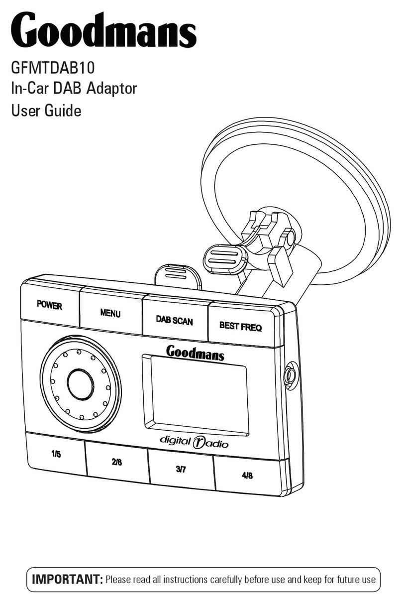
Goodmans GFMTDAB10 User manual

Goodmans

Goodmans GFMTDAB10 User manual

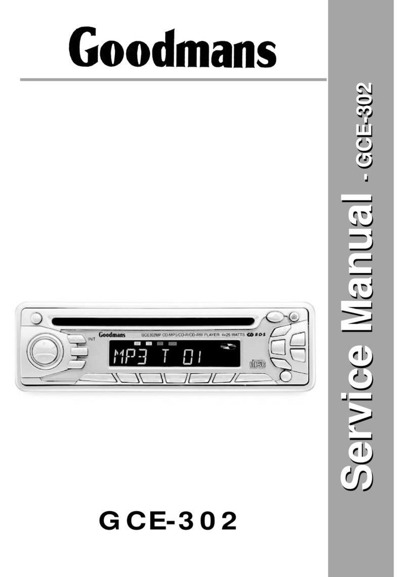
Goodmans GCE-302 User manual

Goodmans

Goodmans GCE-302 User manual

Goodmans GCE 751PLL User manual

Goodmans

Goodmans GCE 751PLL User manual

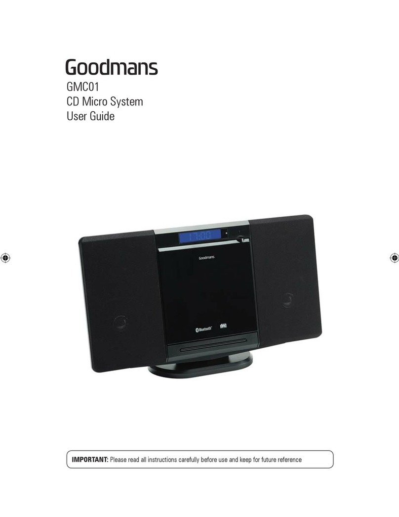
Goodmans GMC01 User manual

Goodmans

Goodmans GMC01 User manual

Goodmans GCE 7301 CD User manual

Goodmans

Goodmans GCE 7301 CD User manual

Goodmans GCE 7205USB3 User manual

Goodmans

Goodmans GCE 7205USB3 User manual

Goodmans GCE7356MP3 User manual

Goodmans

Goodmans GCE7356MP3 User manual

Goodmans GCE 7355 MP3 User manual

Goodmans

Goodmans GCE 7355 MP3 User manual

Goodmans GRC150RD User manual

Goodmans

Goodmans GRC150RD User manual

Popular Car Receiver manuals by other brands

JVC KD-S5M instructions

JVC

JVC KD-S5M instructions

Clarion DVC920 owner's manual

Clarion

Clarion DVC920 owner's manual

Alpine CDE-135EBT owner's manual

Alpine

Alpine CDE-135EBT owner's manual

Pioneer DEH-2500UI/XNUC Service manual

Pioneer

Pioneer DEH-2500UI/XNUC Service manual

Blaupunkt New Orleans MD70 installation instructions

Blaupunkt

Blaupunkt New Orleans MD70 installation instructions

JVC KD-R536 instructions

JVC

JVC KD-R536 instructions

JVC KD-SC800 instructions

JVC

JVC KD-SC800 instructions

JVC KS-F150M Service manual

JVC

JVC KS-F150M Service manual

Advent ADVUNI300 installation guide

Advent

Advent ADVUNI300 installation guide

Hyundai AC110B4GG manual

Hyundai

Hyundai AC110B4GG manual

Sony XR-C5090 operating instructions

Sony

Sony XR-C5090 operating instructions

poly-planar MR50-DVD owner's manual

poly-planar

poly-planar MR50-DVD owner's manual

Blaupunkt Miami Beach CD148 Owner's records

Blaupunkt

Blaupunkt Miami Beach CD148 Owner's records

Blaupunkt atlanta rd 105 operating instructions

Blaupunkt

Blaupunkt atlanta rd 105 operating instructions

Sony CDX-RA700 - Motorized Synchro-flip Detachable... operating instructions

Sony

Sony CDX-RA700 - Motorized Synchro-flip Detachable... operating instructions

Sony CDX-DAB500U operating instructions

Sony

Sony CDX-DAB500U operating instructions

Sony CDX-GT09 operating instructions

Sony

Sony CDX-GT09 operating instructions

Sony CDX-GT35U - Fm/am Compact Disc Player operating instructions

Sony

Sony CDX-GT35U - Fm/am Compact Disc Player operating instructions

manuals.online logo
manuals.online logoBrands
  • About & Mission
  • Contact us
  • Privacy Policy
  • Terms and Conditions

Copyright 2025 Manuals.Online. All Rights Reserved.