P. 10
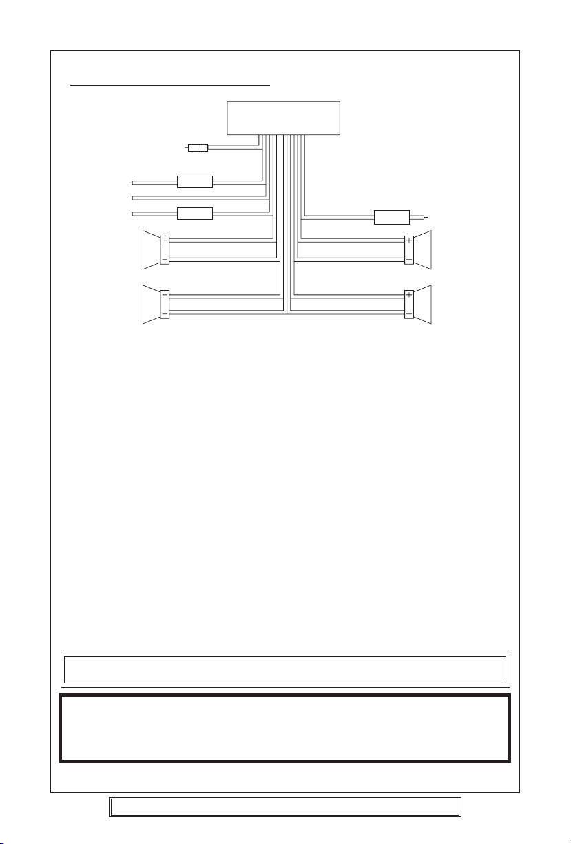
WIRING IDENTIFICATION
REAR VIEW OF PLAYER
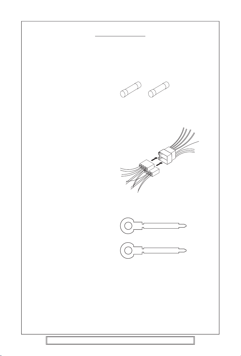
1) AERIAL INPUT SOCKET 8) FRONT RIGHT POSITIVE: WHITE
2) BATTERY: RED +12 VOLT IGNITION 9) FRONT RIGHT NEGATIVE: WHITE
3) GROUND: BLACK –WITH BLACK STRIPE
4) MEMORY: ORANGE 10) REAR LEFT POSITIVE: BROWN
PERMANENT +12 VOLT 11) REAR LEFT NEGATIVE: BROWN
5) AUTO AERIAL: ORANGE/WHITE WITH BLACK STRIPE
6) FRONT LEFT POSITIVE: GREY 12) REAR RIGHT POSITIVE: YELLOW
7) FRONT LEFT NEGATIVE: GREY 13) REAR RIGHT NEGATIVE: YELLOW
WITH BLACK STRIPE WITH BLACK STRIPE
RECOMMENDED MINIMUM LOUDSPEAKER POWER RATINGS
Front loudspeakers power ratings 2 x 30 Watts RMS (2 x 60 Watts Music)
Rear loudspeakers power ratings 2 x 30 Watts RMS (2 x 60 Watts Music)
TWO SPEAKER WIRING
If you intend to use only two speakers with this radio select either front or rear wiring
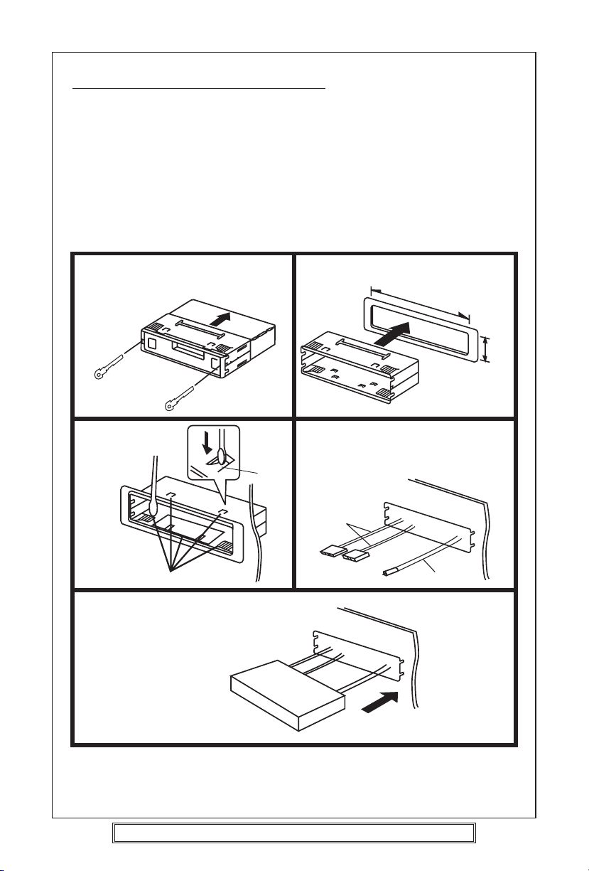
INSTALLATION NOTES
(APPLICABLE TO BOTH 2 AND 4 SPEAKER CONNECTION)
This radio contains two separate power amplifiers, to prevent possible damage to these
amplifiers please ensure:
1) The vehicle chassis is not used as a loudspeaker earth (–ve return).
2) Front and Rear loudspeaker connecting wires are not joined together.
3) Any wires not used when completing a two speaker installation are fully insulated.
4) The memory wire (Orange) is connected to a permanent +12V supply.
5) The power wire (Red) is connected via the ignition switch of the vehicle.
UNIT
1
3
2
45
8
9
6
7
1210
1311
Note: Before turning the unit ON for the first time after installation please ensure the
RESET button is pressed to reset the microprocessor.
IMPORTANT NOTE
If after directly connecting the unit via the vehicles ISO connector plugs it does not appear
to work (fails) to power up disconnect the orange lead bullet connector and reconnect to
the twin bullet connector socket on the red wire. Try the unit again it should power up and
can be used normally. Note this phenomenon is most frequent in Volkswagen/Audi vehicles.
Goodmans Product Information Helpline (0870) 873 0080