Gorgy Timing RT B GPS User manual

2MDE-RTBGPS-4080V1.2
ATTENTION ! Avant de commencer l’installation de votre matériel, lisez attentive-
ment la section suivante qui décrit les consignes de sécurité à respecter au cours
de l’installation.
Pour protéger votre matériel, branchez le sur une prise ondulée.
L’installation électrique sur laquelle le matériel est raccordé doit être réalisée
conformément à la norme NF C 15-100 .
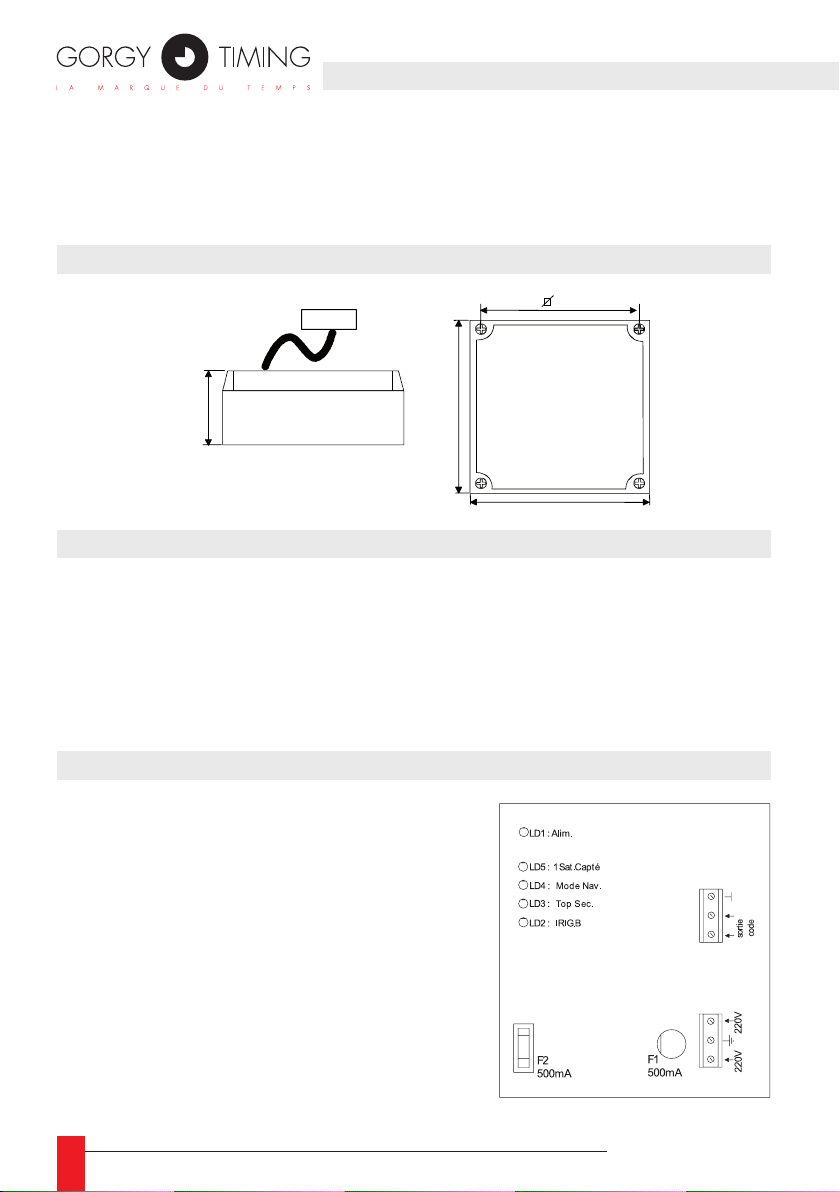
Cet appareil ne comporte pas d’interrupteur d’alimentation primaire : un dispositif
de coupure (disjoncteur ou interrupteur sectionneur), rapidement accessible, doit
être incorporé dans l’installation de câblage. Ce dispositif doit supporter les va-
leurs de tension et courant nominales indiquées sur l’appareil.
En Europe : dans le cadre de la protection des individus et de l'environnement,
il vous incombe de vous débarrasser de cet équipement dans un site de collecte
prévu à cet effet (séparément des ordures ménagères). Pour de plus amples
informations, contactez votre revendeur, votre site de collecte ou les autorités
locales compétentes.
Toute modication ou ouverture du produit sans l’accord du SAV entraîne la perte
de la garantie.
Toute opération de maintenance doit être effectuée hors-tension, y compris pour
les systèmes reliés aux éventuelles sorties sur relais.
D’une façon générale, les câbles de puissance (alimentation 220V) et de signaux
(information horaire) ne doivent pas être trop proches les uns des autres, pour
éviter toute perturbation. (garder quelques centimètres de distance)
Gorgy Timing décline toute responsabilité en cas d’accidents ou de dommages
provoqués par une mauvaise utilisation du produit.
Les produits GORGY TIMING sont conformes aux normes : CE, EN 60950, EN 55022,
EN 50024.
CONSIGNES DE SÉCURITÉ IMPORTANTES
SOMMAIRE

MDE-RTBGPS-4080V1.2 3
SOMMAIRE
1. PRÉSENTATION............................................................................................................ 4
2. DIMENSIONS BOÎTIER ................................................................................................. 4
3. COMPOSITION DU GÉNÉRATEUR ............................................................................. 4
4. PRÉSENTATION DU BOÎTIER ..................................................................................... 4
5. VERSION D’ALIMENTATION ........................................................................................ 5
5.1. Alimentation 230V ou 115V (selon transfo) .......................................................................... 5
5.2. Alimentation 12 ou 24 VDC(non isolée)................................................................................ 6
5.3. Alimentation 18-72 VDC (isolée) .......................................................................................... 6
6. CONNEXION DU GÉNÉRATEUR RT B GPS ............................................................... 7
6.1. Contraintes d’installation ...................................................................................................... 7
6.2. Raccordement sur une centrale RT4000 ou RT1000........................................................... 7
7. MISE EN ROUTE DU GÉNÉRATEUR RT B GPS......................................................... 7
7.1. Mise sous tension................................................................................................................. 7
7.2. Phase d’initialisation............................................................................................................. 7
7.3. Message transmis ................................................................................................................ 9
7.4. Straps de conguration....................................................................................................... 10
8. EN CAS DE... .............................................................................................................11
9. CARACTÉRISTIQUES TECHNIQUES.........................................................................11
FRANCAIS

4MDE-RTBGPS-4080V1.2
Le générateur RT B GPS est un appareil récepteur du système de satellites GPS (Global
Positionning System) délivrant une heure en code IRIG B ou AFNOR NFS 87500. Il peut
piloter directement, synchroniser une centrale horaire RT4000 ou RT1000 pour des instal-
lations plus importantes.
2. DIMENSIONS BOÎTIER
3. COMPOSITION DU GÉNÉRATEUR
Le RT B GPS est composé :
*D'un boîtier comprenant:
►1 circuit imprimé alimentation, base de temps et générateur du code IRIG B /
AFNOR NFS 87500. Il génère toutes les alimentations de l’appareil.
►1 circuit récepteur GPS qui calcule tous les paramètres d’heure en fonction des
informations transmises par les satellites.
*L’antenne GPS intégrée ou non
4. PRÉSENTATION DU BOÎTIER
Le RT B GPS est équipé de cinq voyants LEDs CMS:
►LD5 : «1 SAT. CAPTE» s’allume dès qu’un satellite
est capté par le récepteur GPS, indiquant le bran-
chement et l’installation corrects d’une antenne ex-
térieure.
►LD4 : «MODE NAV» indique que le récepteur GPS a
calculé sa position et génère le temps UTC en sortie.
►LD3 : «TOP SEC» clignote au rythme de la seconde
lorsque le top PPS est délivré par le récepteur GPS
►LD2 : «IRIG B» clignote au rythme du code IRIG
B délivré sur sa sortie (1000 Hz), indiquant la pré-
sence du code en sortie
►LD1 : «ALIM» indique que le RT B GPS est correc-
tement alimenté.
5. VERSION D’ALIMENTATION1. PRÉSENTATION
Dimensions : 180 x 130 x 75
130
130
75 180

MDE-RTBGPS-4080V1.2 5
5. VERSION D’ALIMENTATION
RÉCAPITULATIF DES VERSIONS D’ALIMENTATION
Version Code article Câblage
230 VAC 4048/0X N°5.1
115 VAC 4048/1X N°5.1
12 ou 24VDC 4048/5X N°5.2
18-72 VDC 4048/9X N°5.3
5.1. ALIMENTATION 230V OU 115V (SELON TRANSFO)
12VDC+
1344 IRIG.B S.C
1
2
3
1
2
3
24VDC+
-
SORTIE
1344 IRIG.B S.C
1
2
3
1
2
3
CODE
1344 IRIG.B S.C
1
2
3
1
2
3
1344 IRIG.B S.C
1
2
3
1
2
3
18/72VDC
12VDC+
SORTIE
1344 IRIG.B S.C
1
2
3
1
2
3
1
2
3
CODE
24VDC+
-
-
+
LN
+-++
-
SORTIE
CODE
SORTIE
CODE
1
2
4
3
original
FRANCAIS

6MDE-RTBGPS-4080V1.2
5.2. ALIMENTATION 12 OU 24 VDC(NON ISOLÉE)
5.3. ALIMENTATION 18-72 VDC (ISOLÉE)
12VDC+
1344 IRIG.B S.C
1
2
3
1
2
3
24VDC+
-
SORTIE
1344 IRIG.B S.C
1
2
3
1
2
3
CODE
1344 IRIG.B S.C
1
2
3
1
2
3
1344 IRIG.B S.C
1
2
3
1
2
3
18/72VDC
12VDC+
SORTIE
1344 IRIG.B S.C
1
2
3
1
2
3
1
2
3
CODE
24VDC+
-
-
+
LN
+-
++
-
SORTIE
CODE
SORTIE
CODE
1
2
4
3
original
12VDC+
1344 IRIG.B S.C
1
2
3
1
2
3
24VDC+
-
SORTIE
1344 IRIG.B S.C
1
2
3
1
2
3
CODE
1344 IRIG.B S.C
1
2
3
1
2
3
1344 IRIG.B S.C
1
2
3
1
2
3
18/72VDC
12VDC+
SORTIE
1344 IRIG.B S.C
1
2
3
1
2
3
1
2
3
CODE
24VDC+
-
-
+
LN
+-++
-
SORTIE
CODE
SORTIE
CODE
1
2
4
3
original
6. CONNEXION DU GÉNÉRATEUR RT B GPS

MDE-RTBGPS-4080V1.2 7
6.1. CONTRAINTES D’INSTALLATION
►L’antenne interne au boitier ou l’antenne extérieure doit être placée impérativement
à l’extérieur et au sommet du bâtiment de façon à ce que l’horizon soit le plus dé-
gagé possible autour de celle-ci.
►Tout bâtiment ou monticule dépassant de plus de 5 degrés la ligne d’horizon peut
occulter un ou plusieurs satellites, diminuant ainsi les performances de l’antenne.
☛Bien que peu perturbée par d’autres systèmes, il faut éviter
d’installer l’antenne directement sous un radar.
6.2. RACCORDEMENT SUR UNE CENTRALE RT4000 OU RT1000
►L’asservissement d’une centrale horaire RT4000 ou RT1000 s’effectue par un sim-
ple câble bilaire, reliant la sortie IRIG B du générateur RT B GPS (borne SORTIE
CODE) aux bornes de raccordement de l’entrée de synchronisation de la centrale
horaire.
►La sortie CODE AFNOR n’est pas polarisée.
7. MISE EN ROUTE DU GÉNÉRATEUR RT B GPS
7.1. MISE SOUS TENSION
►Brancher le 230 volts (115 volts ou 18-72Vdc, 12V ou 24V en option).
7.2. PHASE D’INITIALISATION
►La phase d’initialisation du générateur RT B GPS est entamée au moment où l’ali-
mentation extérieure est présente.
►Au premier satellite capté, le voyant LD5 s’allume.
►Durant cette phase le code IRIG B / AFNOR n’est pas émis.
►Dès que le générateur RT B GPS a reçu sufsamment de satellites pour calculer sa
position ainsi que le temps UTC, le voyant LD4 «MODE NAV» s’allume, et le voyant
LD2 «IRIG B» se met à clignoter.
6. CONNEXION DU GÉNÉRATEUR RT B GPS
FRANCAIS

8MDE-RTBGPS-4080V1.2
►Le voyant LD3 «TOP SEC» indique la présence du top PPS (Pulse Per Second) en
sortie de module GPS.
REMARQUES IMPORTANTES:
☛Pour que l’initialisation soit complète
et que le générateur RT B GPS passe en phase d’exploitation,
il faut qu’il ait trouvé quatre satellites au minimum.
☛Une fois l’initialisation effectuée,
3 satellites sufsent pour conserver la précision du système.
☛La durée de cette phase d’initialisation est d’environ 5 minutes
mais peut être plus longue en fonction des conditions de réception.
☛La conguration du système GPS est sauvegardée
grâce à une pile lithium, permettant ainsi un redémarrage rapide
après une coupure brève de l’alimentation
A la 1ère mise en route, la phase d’initialisation peut durer jusqu’à
15 minutes. Durant cette phase, tous les voyants restent éteints,
sauf LD1.
7. MISE EN ROUTE DU GÉNÉRATEUR RT B GPS

MDE-RTBGPS-4080V1.2 9
7.3. MESSAGE TRANSMIS
Un système de switchs permet de générer un code IRIG B / AFNOR en heure GMT ou
en heure locale d’un pays avec ou sans horaire saisonnier selon le tableau ci-dessous
►Conguration des switchs :
Décalage horaire SW4 SW3 SW2 SW1
0Off Off Off Off
1Off Off Off On
2Off Off On Off
3Off Off On On
4Off On Off Off
5Off On Off On
6Off On On Off
7Off On On On
8 On Off Off Off
9 On Off Off On
10 On Off On Off
11 On Off On On
12 On On Off Off
13 On On Off On
14 On On On Off
15 On On On On
Sens du décalage horaire SW5
Positif (Est) Off
Négatif (Ouest) On
Demi-heure supplémentaire de décalage SW6
Non Off
Oui On
Type d’horaire saisonnier SW8 SW7
Aucun OFF OFF
Européen OFF ON
USA ON OFF
Australien ON ON
7. MISE EN ROUTE DU GÉNÉRATEUR RT B GPS
FRANCAIS

10 MDE-RTBGPS-4080V1.2
7.4. STRAPS DE CONFIGURATION
S2 (S.C)
►Strap non fait : Temporisation permettant la coupure du code IRIG B / AFNOR en
sortie au bout de deux minutes en cas de disparition du signal GPS.
►Strap fait : Pas de temporisation. Le code est émis en permanence après acquisi-
tion des satellites.
S3 (IRIG B)
►Strap non fait : Format de code = AFNOR NFS 87-500 complet.
►Strap fait : Format de code = IRIG B 122.
8. EN CAS DE...
12VDC+
1344 IRIG.B S.C
1
2
3
1
2
3
24VDC+
-
SORTIE
1344 IRIG.B S.C
1
2
3
1
2
3
CODE
1344 IRIG.B S.C
1
2
3
1
2
3
1344 IRIG.B S.C
1
2
3
1
2
3
18/72VDC
12VDC+
SORTIE
1344 IRIG.B S.C
1
2
3
1
2
3
1
2
3
CODE
24VDC+
-
-
+
LN
+-++
-
SORTIE
CODE
SORTIE
CODE
1
2
4
3
original
ON
1
2
3
4
5
6
7
8
S3
IRIG.B
S2
S.C
µP

MDE-RTBGPS-4080V1.2 11
En cas de panne d’alimentation extérieure l’antenne GPS s’arrête de fonctionner et recom-
mencera sa phase d’initialisation dès le retour de l’alimentation.
En cas de perturbation de la réception de satellites le code IRIG B / AFNOR NFS 87500
continue à être transmis sur sa sortie avec la précision de la base de temps interne pen-
dant deux minutes ou indéniment en fonction du strap S2.
9. CARACTÉRISTIQUES TECHNIQUES
ALIMENTATION
►230 volts ou 115 volts +10/-15% 50/60 Hz
►18-72 VDC
►12VDC ou 24VDC
►Consommation maxi : 4 VA
►Filtre antiparasites
BASE DE TEMPS
►Technologie CMOS-HCMOS faible consommation
►Microcontrôleur 80C51
►Quartz 12 MHz assurant une précision de 0,1 seconde par 24 heures entre 10 et 45°C
RÉCEPTEUR
►Huit canaux parallèles permettant le calcul des messages provenant de six satelli-
tes simultanément.
►Sensibilité : -134 dB.
ANTENNE
►Fréquence: 1574,42 +/-1 MHz.
►Impédance 50 ohms.
►Plage de température: -30°C à +85°C.
►Totalement étanche pour l’extérieur (IP65).
SORTIES
►Code IRIG B 122 ou AFNOR NFS 87500
►Fréquence porteuse : 1Khz.
►Niveau 2.2 volts c à c +/- 10%.
►Isolation galvanique par transformateur.
8. EN CAS DE...
FRANCAIS

12 MDE-RTBGPS-4080V1.2
RADIO TIMING®, LEDI ®, LEDI CA®, HANDI ® sont des marques déposées GORGY TIMING.
Numéro de déclaration d’activité de prestataire de formation : 82 38 04877 38
GORGY TIMING RC 74 B 38 - Toutes modications d'ordre technique ou esthétique peuvent être apportées sans préavis.
SUPPORT TECHNIQUE
DEPUIS LA FRANCE SUR UN POSTE FIXE :
GORGY TIMING SAS
Quartier Beauregard
38350 La Mure d'Isère (Grenoble France)
Phone: +33 4 76 30 48 20 Fax: +33 4 76 30 85 33

14 MDE-RTBGPS-4080V1.2
WARNING! Read the section that follows very carefully before installing your equi-
pment. It gives the safety instructions to follow during installation.
To protect your equipment, connect power on UPS (Uninterruptible Power Supply).
The electrical installation to which the equipment is connected must comply with
the NF C 15-100 standard.
This device does not have a primary power switch. A power protection system
(circuit-breaker or disconnecting switch), that is easy to access must be built into
the wiring installation. This device must support the nominal voltage and current
values specied on the clock.
In Europe: to comply with European regulations on the protection of persons and
the environment, you must dispose of this equipment in a collection site provided
for this purpose (separately from household waste). Contact your reseller, collec-
tion site or the competent lcoal authorities for more information.
Toute modication ou ouverture du produit sans l’accord du SAV entraîne la perte
de la garantie.
All maintenance operation shall be conducted with power shut off, including sys-
tems connected on relay outputs if any.
Generally, the power cable (220V) and transmission cable (of time signal) shall
not be very close to each other, so as to avoid interference (keep the distance of
a few centimeters).
Gorgy Timing disclaims all responsibility in case of accident or damage caused by
an improper use of the product.
GORGY TIMING products are compliant with the following standards: CE, EN 60950,
EN 55022, EN 50024
IMPORTANT SAFETY INSTRUCTIONS
CONTENTS

15
MDE-RTBGPS-4080V1.2
CONTENTS
1. PRESENTATION.......................................................................................................... 16
2. DIMENSIONS OF THE CASE...................................................................................... 16
3. COMPOSITION OF THE RT B GPS GENERATOR.................................................... 16
4. RT B GPS CASE ......................................................................................................... 16
5. POWER SUPPLY VERSION........................................................................................ 17
5.1. 230V or 115V...................................................................................................................... 17
5.2. 12 or 24 VDC...................................................................................................................... 18
5.3. 18-72 VDC.......................................................................................................................... 18
6. CONNECTING THE RT B GPS GENERATOR .......................................................... 19
6.1. Instructions for installation.................................................................................................. 19
6.2. Connection to an RT4000 or RT1000 time centre.............................................................. 19
7. STARTING UP THE RT B GPS GENERATOR............................................................ 19
7.1. Switching on ....................................................................................................................... 19
7.2. Initialization phase.............................................................................................................. 19
7.3. Message transmitted .......................................................................................................... 21
7.4. Straps de conguration....................................................................................................... 22
8. IN THE EVENT OF... .................................................................................................... 23
9. TECHNICAL DETAILS................................................................................................. 23
ENGLISH

16 MDE-RTBGPS-4080V1.2
The RT B GPS generator works on the GPS (Global Positioning System) satellite system.
It delivers an IRIG B or AFNOR NFS 87-500 time code. The RT B GPS can work alone, or
it can directly control and synchronize an RT4000 time centre or RT1000 time centre (for
larger installations).
2. DIMENSIONS OF THE CASE
3. COMPOSITION OF THE RT B GPS GENERATOR
The RT B GPS consists of two parts:
*The case comprising:
►1 power supply and time base printed circuit which generates the IRIG B / AFNOR
NFS 87-500 code. It generates all the power supplies for the unit.
►1 GPS receiver printed circuit, which calculates all the time parameters according to
the information transmitted by the satellites.
*The GPS antenna which is integrated or not.
4. RT B GPS CASE
The RT B GPS is equipped with ve SMD LEDs:
►LD5: «1 SAT. PICKED» lights when a satellite is cap-
tured by the GPS receiver, indicating the connection
and the correct installation of an outdoor antenna.
►LD4: «NAV. MODE», indicates that the GPS recei-
ver has computed its position and generates the
UTC time to its output.
►LD3: «PPS PULSE», ashes at the rhythm of second,
indicating that the GPS card generates the PPS.
►LD2: «IRIG B», ashes at the rhythm of transmis-
sion of IRIGB code to its output(1000Hz), indicating
the presence of output code.
►LD1: «POWER», lights as soon as the power sup-
ply is present.
Dimensions : 180 x 130 x 75
130
130
75 180
5. POWER SUPPLY VERSION1. PRESENTATION

17
MDE-RTBGPS-4080V1.2
Summary of power supply version
Version Item code Design
230 VAC 4048/0X N°5.1
115 VAC 4048/1X N°5.1
12 or 24VDC 4048/5X N°5.2
18-72 VDC 4048/9X N°5.3
5.1. 230V OR 115V
12VDC+
1344 IRIG.B S.C
1
2
3
1
2
3
24VDC+
-
SORTIE
1344 IRIG.B S.C
1
2
3
1
2
3
CODE
1344 IRIG.B S.C
1
2
3
1
2
3
1344 IRIG.B S.C
1
2
3
1
2
3
18/72VDC
12VDC+
SORTIE
1344 IRIG.B S.C
1
2
3
1
2
3
1
2
3
CODE
24VDC+
-
-
+
LN
+-++
-
SORTIE
CODE
SORTIE
CODE
1
2
4
3
original
5. POWER SUPPLY VERSION
OUTPUT
CODE
ENGLISH

18 MDE-RTBGPS-4080V1.2
5.2. 12 OR 24 VDC
5.3. 18-72 VDC
12VDC+
1344 IRIG.B S.C
1
2
3
1
2
3
24VDC+
-
SORTIE
1344 IRIG.B S.C
1
2
3
1
2
3
CODE
1344 IRIG.B S.C
1
2
3
1
2
3
1344 IRIG.B S.C
1
2
3
1
2
3
18/72VDC
12VDC+
SORTIE
1344 IRIG.B S.C
1
2
3
1
2
3
1
2
3
CODE
24VDC+
-
-
+
LN
+-
++
-
SORTIE
CODE
SORTIE
CODE
1
2
4
3
original
12VDC+
1344 IRIG.B S.C
1
2
3
1
2
3
24VDC+
-
SORTIE
1344 IRIG.B S.C
1
2
3
1
2
3
CODE
1344 IRIG.B S.C
1
2
3
1
2
3
1344 IRIG.B S.C
1
2
3
1
2
3
18/72VDC
12VDC+
SORTIE
1344 IRIG.B S.C
1
2
3
1
2
3
1
2
3
CODE
24VDC+
-
-
+
LN
+-++
-
SORTIE
CODE
SORTIE
CODE
1
2
4
3
original
6. CONNECTING THE RT B GPS GENERATOR
OUTPUT
CODE
OUTPUT
CODE

19
MDE-RTBGPS-4080V1.2
6.1. INSTRUCTIONS FOR INSTALLATION
►The antenna must be placed outdoor at the top of a building in order to obtain the
widest possible unobstructed horizon around it. Any building or small hill more than
5 degrees above the line of the horizon may obstruct one or more satellites, thus
reducing the performance of the antenna.
☛Although other systems do not cause much interference to the
antenna, it must not be installed directly beneath radar.
6.2. CONNECTION TO AN RT4000 OR RT1000 TIME CENTRE
►An RT3000 or RT1000 time centre is linked by a single two-wire cable connecting
the IRIG B / AFNOR output on the RT B GPS generator (terminal B1) to the syn-
chronization input connection terminals on the time centre.
►The Afnor output is without polarity.
7. STARTING UP THE RT B GPS GENERATOR
7.1. SWITCHING ON
►Connect the 230 VAC supply (115 VAC or 18-72 VDC, 12VDC or 24VDC as
options).
7.2. INITIALIZATION PHASE
►The initialization phase of the RT B GPS generator starts as soon as the external
power supply is present.
►When the rst satellite is locked, indicator LD5 lights.
►The IRIG B / AFNOR code is not transmitted during this phase.
►As soon as the RT B GPS acquires a number of satellites that permits to compute
its position and the UTC time, the «NAV. MODE» indicator LD4 lights and the «IRIG
B» indicator LD2 starts to ash.
►The “PPS PULSE” indicator LD3 shows the PPS (Pulse per second) that is gene-
rated by the GPS card.
6. CONNECTING THE RT B GPS GENERATOR
ENGLISH

20 MDE-RTBGPS-4080V1.2
IMPORTANT NOTES:
☛ The RT B GPS generator must nd at least four satellites for
the initialization to be complete and to switch to operating mode.
After that, three satellites are sufcient to keep the time precision.
☛The initialization phase takes approximately 5 minutes but may
be longer, depending on the reception conditions.
☛ The conguration of the GPS system is protected by a lithium
battery, which also enables a rapid restart after a brief break in the
power supply.
When running for the rst time, the stage of initialization can have
duration of 15 minutes. During this stage, all the lights are off,
except the LD1 light.
7. STARTING UP THE RT B GPS GENERATOR
Table of contents
Languages:
Popular Inverter manuals by other brands

Black & Decker
Black & Decker bdv066 instruction manual

Hoymiles
Hoymiles HYS-8.0LV-EUG2 Quick installation guide

Victron energy
Victron energy Phoenix MultiPlus 12/3000/120 manual

LG
LG SIMs 2.0 user manual

COMPANION
COMPANION EPAK instruction manual

IRFTS
IRFTS EASY ROOF EVOLUTION L1 installation instructions