manuals.online logo
Brands
  1. Home
  2. •
  3. Brands
  4. •
  5. GORMAN-RUPP
  6. •
  7. Water Pump
  8. •
  9. GORMAN-RUPP AMT GCW Series Assembly instructions

GORMAN-RUPP AMT GCW Series Assembly instructions

Specications Information and Repair Parts Manual GCW Series
GCWX-250-00 1 4/2021
Please read and save this Repair Parts Manual. Read this manual and the General Operating Instructions carefully before attempting to assemble, install, operate
or maintain the product described. Protect yourself and others by observing all safety information. The Safety Instructions are contained in the General Operating
Instructions. Failure to comply with the safety instructions accompanying this product could result in personal injury and/or property damage! Retain instructions
for future reference. AMT reserves the right to discontinue any model or change specications at any time without incurring any obligation.
©2021 AMT Pump Company, A Subsidiary of The Gorman-Rupp Company, All Rights Reserved.
Periodic maintenance and inspection is required on all pumps to ensure proper operation. Unit must be clear of debris and sediment. Inspect for leaks and loose bolts. Failure to do so
voids warranty.
Aluminum General Purpose Pumps
Refer to pump manual 1808-633-00 for General Operating and Safety Instructions.
MAINTENANCE
To prevent accidental starting, always remove spark plug or disconnect
and ground spark plug wire before attempting to service or remove any
component.
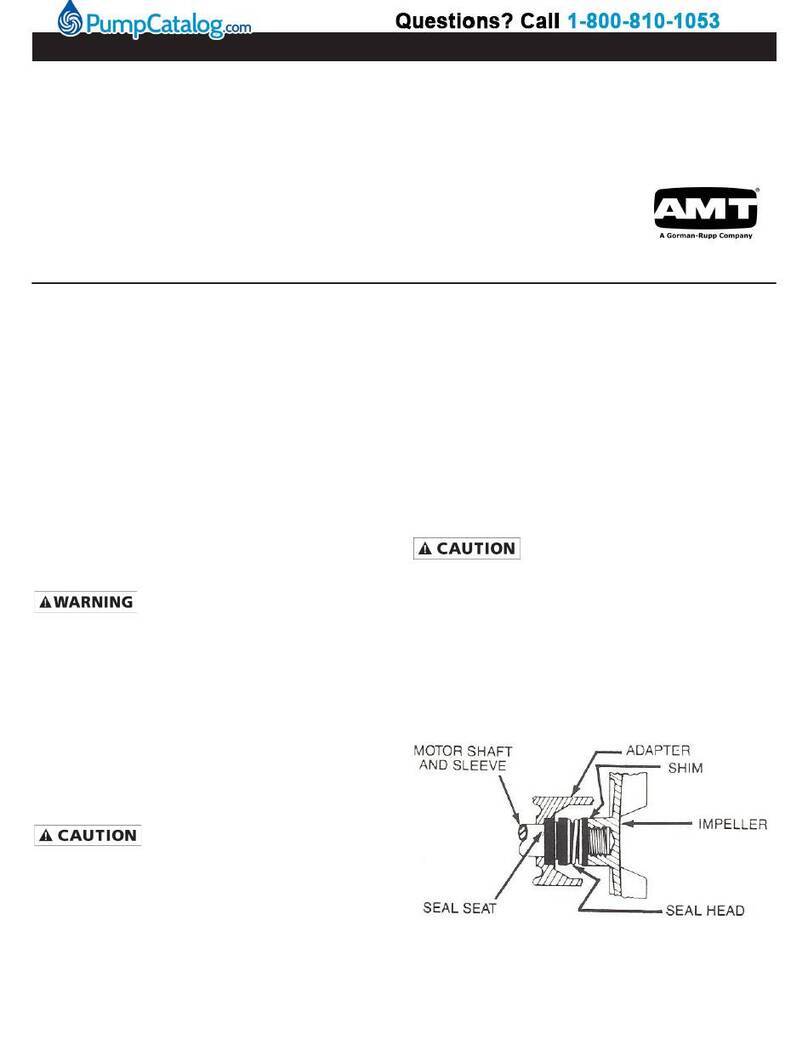
MECHANICAL SEAL REPLACEMENT
Refer to gures 1, 2 and 3.
IMPORTANT: Always replace both seal seat and seal head (Ref. No. 9) to
ensure proper mating of components!
1. Unthread fasteners (Ref. No. 15) and remove casing (Ref. No. 13) and
casing seal (Ref. No. 11).
2. Remove volute (Ref. No. 10).
3. Unscrew impeller fastener (Ref. No. 8) from motor shaft (fastener
unscrews CCW looking at motor shaft).
NOTE: To prevent shaft from turning, remove shroud from engine and hold the
ywheel in place.
4. Remove keyed impeller (Ref. No. 7) from motor shaft. Remove shims
(Ref. No. 6) DO NOT LOSE SHIMS.
5. Pry seal seat from recess of impeller.
6. Remove the adapter (Ref. No. 2) by unthreading fasteners (Ref. No. 4).
7. Press seal head from rear of adapter.
8. Clean adapter and impeller seal recesses and motor shaft. Make certain
all surfaces are perfectly clean before installing new seal parts.
Handle seal parts with extreme caution and keep them clean. Do not
touch polished seal faces with your hands. Do not apply lubricants on
seal faces. This could cause a leak or premature seal failure.
9. Apply a light coat of sealing compound to new seal head (See Figure 1)
and press it into adapter recess using proper size tube or installation tool
(see Figure 2). DO NOT press on carbon face. Install using ange only.
10. Slide adapter onto motor mounting face. Attach with fasteners.
11. Press new seal seat squarely into impeller recess. Avoid scratching
polished surface.
NOTE: Use a soft, clean piece of cloth on seal seat face when installing to
prevent marring.
12. Replace any shim washers which may have been removed in disassembly
(see SHIM ADJUSTMENT). Using key, put the impeller back in place.
13. Install and tighten impeller screw.
14. Reinstall volute and remount casing with fasteners.
NOTE: Volute gets placed inside casing before mounitng casing to adapter.
NOTE: Always ush pump thoroughly before use so as not to contaminate
liquid being pumped. If impeller is replaced, seal assembly should also be
replaced as seal is usually damaged in disassembly.
SHIM ADJUSTMENT
When installing a replacement impeller, it may be necessary to vary number of
shims that will be required. This is done by adding 0.010” shim more than was
removed and reassembling pump as follows:
IMPORTANT: When clearance between impeller and volute exceeds 1/16” at
face of impeller or 1/8” on outside diameter of impeller, it may be necessary to
take corrective action.
1. Ensure that casing is snugly in place and check shaft to make sure it is
turning freely. If it turns freely, check to ensure that adapter and casing
are seated rmly, compressing gasket where they meet. If they are not
seated, tighten fasteners and recheck shaft for free turning. Tighten
carefully, turning shaft while tightening. If shaft seizes before fasteners
are completely tight, disassembly pump, remove one shim and repeat
reassembly.
2. If at any time during shim adjustment shaft does not turn free, or a metal-
to-metal rubbing can be heard or felt when turning shaft, repeat SHIM
ADJUSTMENT procedure.
NOTE: Impeller must be as close as possible to volute in order to perform
properly and retain suction capabilities.
DESCRIPTION
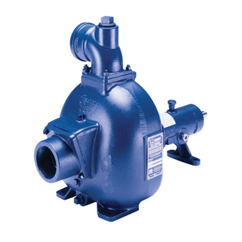
These pumps are engine driven, self-priming (to 20 ft. lift), portable units. Clog resistant impeller is capable of handling solids up to 1/4” diameter (2”=3/16” &
3”=1/4”). For use with non-ammable, non-abrasive liquids compatible with pump component materials.
Figure 1 - Mechanical Seal Replacement
Figure 2 - Seal Installation Tool (Ref. No. 31)
Specications Information and Repair Parts Manual GCW Series
GCWX-250-00 2 4/2021
For Repair Parts contact dealer where pump was purchased.
Please provide following information:
-Model Number
-Serial Number (if any)
Part description and number as shown in parts list
Figure 3 - Repair Parts Illustrations
Aluminum General Purpose Pumps
Specications Information and Repair Parts Manual GCW Series
GCWX-250-00 3 4/2021
Repair Parts List
Ref Part Number for Models
No. Description GCW2 GCW3 Qty
1 Engine 1639-040-00 1639-040-00 1
2 Adapter Kit GCW2-030-96 GCW3-030-96 1
(includes Ref. Nos. 2, 3 and 4)
3 Flat Washer Incl. w/Ref. 2 Incl. w/Ref. 2 4
4 Adapter Bolt Incl. w/Ref. 2 Incl. w/Ref. 2 4
5 Impeller Key Incl. w/Ref. 7 Incl. w/Ref. 7 1
6 Impeller Shims Incl. w/Ref. 7 Incl. w/Ref. 7 1
7 Impeller Kit GCW2-010-95 GCW3-010-95 1
(includes Ref. Nos. 5, 6, 7 and 8)
8 Impeller Bolt Incl. w/Ref. 7 Incl. w/Ref. 7 1
9 Mechanial Seal Kit GCW2-301-90 GCW2-301-90 1
(includes Ref. Nos. 9 and 31)
10 Volute GCW2-150-95 GCW3-150-95 1
11 Casing O-Ring Incl. w/Ref. KIT Incl. w/Ref. KIT 1
12 Volute Gasket Incl. w/Ref. KIT Incl. w/Ref. KIT 1
13 Casing Kit GCW2-001-96 GCW3-001-96 1
(includes Ref. Nos. 13, 14 and 15)
14 Washers Incl. w/Ref. 13, 19 and 22 Incl. w/Ref. 13, 19 and 22 11
15 Casing Bolt Incl. w/Ref. 13 Incl. w/Ref. 13 4
16 Plug O-Ring Incl. w/Ref. KIT Incl. w/Ref. KIT 2
17 Plug Incl. w/Ref. KIT Incl. w/Ref. KIT 2
18 Flapper Valve Incl. w/Ref. KIT Incl. w/Ref. KIT 1
19 Suction Flange Kit NPT GCW2-050-96 GCW3-050-96 1
Suction Flange Kit BSP GCW2-052-96 GCW3-052-96 1
(includes Ref. Nos. 14, 19 and 20)
20 Flange Bolt Incl. w/Ref. 19 and 22 Incl. w/Ref. 19 and 22 7
21 Discharge Gasket Incl. w/Ref. KIT Incl. w/Ref. KIT 1
22 Discharge Flange Kit NPT GCW2-080-96 GCW3-080-96 1
Discharge Flange Kit BSP GCW2-082-96 GCW3-082-96 1
(includes Ref. Nos. 14, 20, and 22)
23 Frame Kit 2760-104-K0 2760-104-K0 1
(includes Ref. Nos. 23, 27, 28 and 29)
24 Engine Mounting Hardware Kit C403-420-92 C403-420-92 4
(includes Ref. Nos. 24, 25, 26 and 27)
25 Engine Bolts Incl. w/Ref. 24 Incl. w/Ref. 24 4
26 Washers Incl. w/Ref. 24 Incl. w/Ref. 24 4
27 Hex Nuts Incl. w/Ref. 23 and 24 Incl. w/Ref. 23 and 24 8
28 Rubber Feet Incl. w/Ref. 23 Incl. w/Ref. 23 4
29 Rubber Feet Bolts Incl. w/Ref. 23 Incl. w/Ref. 23 4
30 Suction Strainer (not shown) GCW2-170-90 GCW3-170-90 1
31 Seal Installation Tool (not shown, See Figure 2) Incl. w/Ref. 9 Incl. w/Ref. 9 1
KIT Gasket/O-Ring Kit GCW2-300-90 GCW3-300-90 1
(includes Ref. Nos. 11, 12, 16, 17, 18 and 21)
**** Raising blocks not necessary for 2” Pump
Specications Information and Repair Parts Manual GCW Series
GCWX-250-00 4 4/2021

This manual suits for next models

2

Other GORMAN-RUPP Water Pump manuals

GORMAN-RUPP SF4C Application guide

GORMAN-RUPP

GORMAN-RUPP SF4C Application guide

GORMAN-RUPP PA12A60-B-QSB4.5P User manual

GORMAN-RUPP

GORMAN-RUPP PA12A60-B-QSB4.5P User manual

GORMAN-RUPP PAH SERIES User manual

GORMAN-RUPP

GORMAN-RUPP PAH SERIES User manual

GORMAN-RUPP SFDV3A Application guide

GORMAN-RUPP

GORMAN-RUPP SFDV3A Application guide

GORMAN-RUPP AMT 316T-95 Assembly instructions

GORMAN-RUPP

GORMAN-RUPP AMT 316T-95 Assembly instructions

GORMAN-RUPP PA6D60-4045T User manual

GORMAN-RUPP

GORMAN-RUPP PA6D60-4045T User manual

GORMAN-RUPP PA Series User manual

GORMAN-RUPP

GORMAN-RUPP PA Series User manual

GORMAN-RUPP SF4F Application guide

GORMAN-RUPP

GORMAN-RUPP SF4F Application guide

GORMAN-RUPP GHA SERIES User manual

GORMAN-RUPP

GORMAN-RUPP GHA SERIES User manual

GORMAN-RUPP 12B2-B User manual

GORMAN-RUPP

GORMAN-RUPP 12B2-B User manual

GORMAN-RUPP AMT 368C-98 Assembly instructions

GORMAN-RUPP

GORMAN-RUPP AMT 368C-98 Assembly instructions

GORMAN-RUPP SUPER U SERIES User manual

GORMAN-RUPP

GORMAN-RUPP SUPER U SERIES User manual

GORMAN-RUPP HO3/4A4-36DK User manual

GORMAN-RUPP

GORMAN-RUPP HO3/4A4-36DK User manual

GORMAN-RUPP PAH SERIES Application guide

GORMAN-RUPP

GORMAN-RUPP PAH SERIES Application guide

GORMAN-RUPP 14C2-F3L User manual

GORMAN-RUPP

GORMAN-RUPP 14C2-F3L User manual

GORMAN-RUPP Patterson PM1 Series Assembly instructions

GORMAN-RUPP

GORMAN-RUPP Patterson PM1 Series Assembly instructions

GORMAN-RUPP HO Series User manual

GORMAN-RUPP

GORMAN-RUPP HO Series User manual

GORMAN-RUPP AMT 5585-B6 Assembly instructions

GORMAN-RUPP

GORMAN-RUPP AMT 5585-B6 Assembly instructions

GORMAN-RUPP PAH SERIES Application guide

GORMAN-RUPP

GORMAN-RUPP PAH SERIES Application guide

GORMAN-RUPP SUPER T SERIES User manual

GORMAN-RUPP

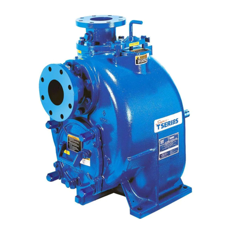
GORMAN-RUPP SUPER T SERIES User manual

GORMAN-RUPP 0 SERIES User manual

GORMAN-RUPP

GORMAN-RUPP 0 SERIES User manual

GORMAN-RUPP AMT 576E-95 Assembly instructions

GORMAN-RUPP

GORMAN-RUPP AMT 576E-95 Assembly instructions

GORMAN-RUPP AMT 5586-H6 User manual

GORMAN-RUPP

GORMAN-RUPP AMT 5586-H6 User manual

GORMAN-RUPP S8A1-E95 460/3 Application guide

GORMAN-RUPP

GORMAN-RUPP S8A1-E95 460/3 Application guide

Popular Water Pump manuals by other brands

Bosch Rexroth 63 Series instruction manual

Bosch

Bosch Rexroth 63 Series instruction manual

yellow jacket BULLET X Operation and maintenance manual

yellow jacket

yellow jacket BULLET X Operation and maintenance manual

Hytorc HY-Ex Translation of the original operating instructions

Hytorc

Hytorc HY-Ex Translation of the original operating instructions

Atlas Copco LRP 700 VSD+ Instruction book

Atlas Copco

Atlas Copco LRP 700 VSD+ Instruction book

BGS technic 1609 instruction manual

BGS technic

BGS technic 1609 instruction manual

Pfeiffer Vacuum HENA 201 R operating instructions

Pfeiffer Vacuum

Pfeiffer Vacuum HENA 201 R operating instructions

ARO 67151-*-*11 series Operator's manual

ARO

ARO 67151-*-*11 series Operator's manual

Taco 0015e3 instruction sheet

Taco

Taco 0015e3 instruction sheet

Bosch Rexroth Sytronix SvP 70 Series Operating	 instruction

Bosch

Bosch Rexroth Sytronix SvP 70 Series Operating instruction

CET PFP-20hpHND-HP Instruction handbook

CET

CET PFP-20hpHND-HP Instruction handbook

North Star S 10633 owner's manual

North Star

North Star S 10633 owner's manual

Kärcher SCP 9000 Original instructions

Kärcher

Kärcher SCP 9000 Original instructions

Grundfos UPS 15-40 130 manual

Grundfos

Grundfos UPS 15-40 130 manual

Dover Wilden Original Series Engineering, operation & maintenance

Dover

Dover Wilden Original Series Engineering, operation & maintenance

Idex VIKING PUMP 4124B Series Technical & service manual

Idex

Idex VIKING PUMP 4124B Series Technical & service manual

Powermate PP0100363 owner's manual

Powermate

Powermate PP0100363 owner's manual

Franklin Electric Little Giant 5-APCP instructions

Franklin Electric

Franklin Electric Little Giant 5-APCP instructions

Graco 222-832 Instructions-parts list

Graco

Graco 222-832 Instructions-parts list

manuals.online logo
manuals.online logoBrands
  • About & Mission
  • Contact us
  • Privacy Policy
  • Terms and Conditions

Copyright 2025 Manuals.Online. All Rights Reserved.