manuals.online logo
Brands
  1. Home
  2. •
  3. Brands
  4. •
  5. GORMAN-RUPP
  6. •
  7. Water Pump
  8. •
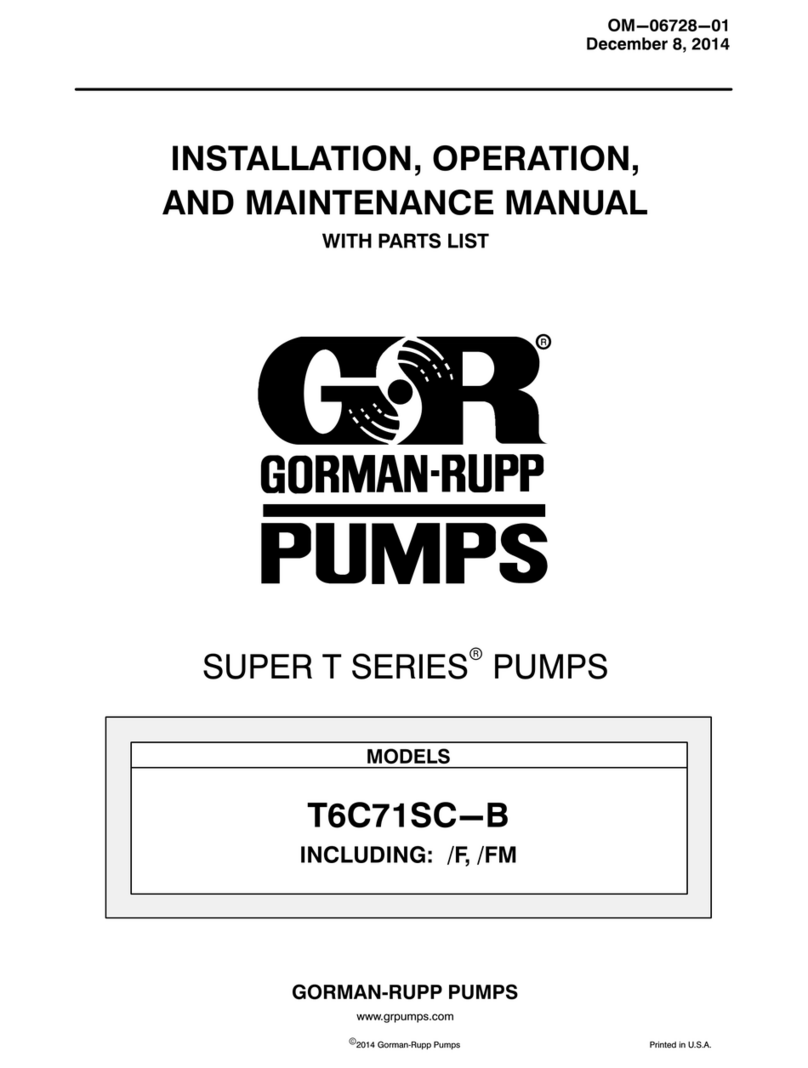
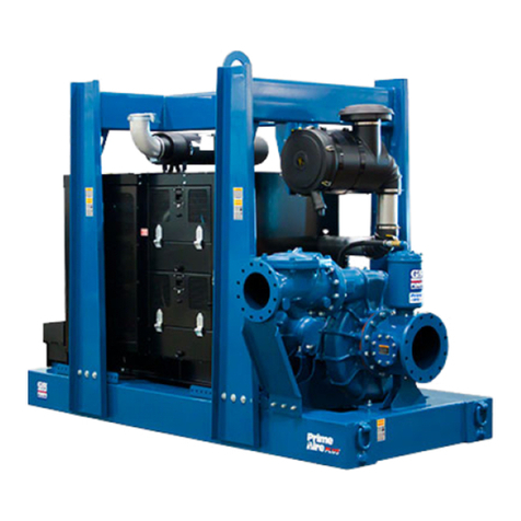
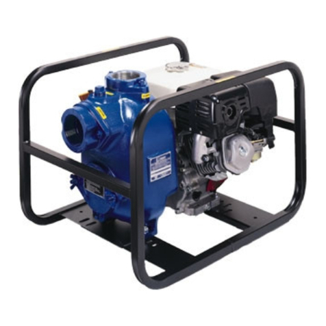
  9. GORMAN-RUPP PRIME-AIRE PA4B Series Operating instructions

GORMAN-RUPP PRIME-AIRE PA4B Series Operating instructions

PUBLICATION NUMBER MR--04835
March 25, 1998
Rev. A 04/23/99
Use With: OM--04402
THE GORMAN-RUPP COMPANY DMANSFIELD, OHIO
GORMAN-RUPP OF CANADA LIMITED DST. THOMAS, ONTARIO, CANADA Printed in U.S.A.
ECopyright by the Gorman-Rupp Company
PRIME-AIREr
rr
rSERIES
PA4B Model Pumps
(Including Model 64B Pump Ends)
The engine exhaust from this
product contains chemicals
known tothe State ofCaliforniato
cause cancer, birth defects or
other reproductive harm.
MR--04835 PA SERIES PUMPS
PAGE I -- 1
INTRODUCTION
INTRODUCTION
Thank You for purchasing a Gorman-Rupp Prime-
AirerSeries priming-assisted pump. Read this
manual carefully to learn how to safely maintain
and service your pump. Failure to do so could re-
sult in personal injury or damage to the pump.
A set of three manuals accompanies your pump.
TheInstallation/OperationManualcontainsessen-
tial information on installing and operating the
pump, and on making electrical connections. The
Parts List Manual provides performance curve(s),
a pump model cross-section drawing, and parts
listforyourpump.
This Maintenance and Repair Manual provides
troubleshooting instructions required to properly
diagnose operational problems. Maintenance in-
structions within this manual are limited to the
pump hydraulic and drive components only. For
maintenance and repair of the engine or air com-
pressor,consulttheseparateliteratureprovidedby
the manufacturers.
This manual covers high head PA Series priming-
assisted models, which incorporate a 60 Series
straight centrifugal pump end. The pump is de-
signed for high pressure distribution of non-vola-
tile, non-flammable liquids that do not contain
largeentrainedsolids. Forspecific service,contact
your Gorman-Rupp distributor or the Gorman-
Rupp Company.
As described on the following page, this manual
willalert personnel toknown procedures which re-
quire specialattention, to those which could dam-
age equipment, and to those which could be dan-
gerous topersonnel. However, this manualcannot
possibly anticipate and provide detailed precau-
tions for every situation that might occur during
maintenanceoftheunit.Therefore,itistherespon-
sibility of the owner/maintenance personnel to en-
sure that only safe, established maintenance pro-
ceduresareused, andthatanyproceduresnotad-
dressedinthismanualareperformedonlyafteres-
tablishingthatneitherpersonalsafetynorpumpin-
tegrity are compromised by such practices.
If there are any questions regarding the pump
which are not covered in this manual orin other lit-
erature accompanying the unit, please contact
your Gorman-Rupp distributor or the Gorman-
Rupp Company:
The Gorman-Rupp Company
P.O. Box 1217
Mansfield, Ohio 44901--1217
or
Gorman-Rupp of Canada Limited
70 Burwell Road
St. Thomas, Ontario N5P 3R7
CONTENTS
SAFETY -- SECTION A
TROUBLESHOOTING -- SECTION B
PUMP MAINTENANCE AND REPAIR -- SECTION C
DRAWINGS AND IDENTIFICATION LISTS PAGES C --- 2 THRU C---7...........................
PUMP AND SEAL DISASSEMBLY AND REASSEMBLY PAGE C --- 8............................
Air Compressor Drive Belt Tensioning For Deutz Engine Driven Models PAGE C --- 9...........
Priming Chamber Removal and Disassembly PAGE C --- 9.................................
Discharge Check Valve Removal and Disassembly PAGE C --- 9............................
Suction Head Removal PAGE C --- 9.....................................................
Impeller Removal PAGE C --- 10.........................................................
Seal Removal and Disassembly PAGE C --- 10............................................
Pump Casing Removal PAGE C --- 10....................................................
Separating Intermediate and Drive Assembly From Engine PAGE C --- 10....................
Shaft And Bearing Removal And Disassembly PAGE C --- 11................................
Shaft and Bearing Reassembly and Installation PAGE C --- 11...............................
Securing Intermediate And Drive Assembly To Engine PAGE C --- 12.........................
MR--04835PA SERIES PUMPS
PAGE I -- 2 INTRODUCTION
Pump Casing Installation PAGE C --- 14..................................................
Seal Reassembly and Installation PAGE C --- 14...........................................
Impeller Installation PAGE C --- 15.......................................................
Suction Head Installation PAGE C --- 16..................................................
Discharge Check Valve Assembly And Installation PAGE C --- 16............................
Priming Chamber Assembly And Installation PAGE C --- 17.................................
Final Pump Assembly PAGE C --- 17.....................................................
LUBRICATION PAGE C --- 17..............................................................
Seal Assembly PAGE C --- 17...........................................................
Bearings PAGE C --- 18................................................................
Engine PAGE C --- 18..................................................................
RECORDING MODEL AND
SERIAL NUMBERS
Please record the pump modeland serial number
in the spaces provided below. Your Gorman-Rupp
distributorneedsthisinformationwhenyourequire
parts or service.
Pump Model:
Serial Number:
WARRANTY INFORMATION
The warranty provided with your pump is part of
Gorman-Rupp’s support program for customers
who operate and maintain their equipment as de-
scribed in this and the other accompanying litera-
ture. Please note that should the equipment be
abused or modified to change its performance be-
yond the original factory specifications, the war-
ranty will become void and any claim will be de-
nied.
The following are used to alert personnel to procedures which require special attention, to those which
could damage equipment, and to those which could be dangerous to personnel:
Immediate hazards which WILL result in
severe personal injury or death. These
instructions describe the procedure re-
quired and the injury which will result
from failure to follow the procedure.
Hazards or unsafe practices which
COULD result in severe personal injury
or death. These instructions describe
the procedure required and the injury
which could result from failure to follow
the procedure.
HazardsorunsafepracticeswhichCOULD
resultinminorpersonalinjuryorproductor
property damage. These instructions de-
scribe the requirements and the possible
damage which could result from failure to
follow the procedure.
NOTE
Instructions to aid in installation, operation, and
maintenance or which clarify a procedure.
MR--04835 PA SERIES PUMPS
PAGE A -- 1
SAFETY
SAFETY --- SECTION A
The following information applies
throughout this manual to Gorman-
Rupp Prime Airer
rr
rSeries pumps.
This manual will alert personnel to
known procedures which require spe-
cial attention, to those which could
damage equipment, and to those which
could be dangerous to personnel.How-
ever,thismanualcannotpossiblyantici-
pate and provide detailed instructions
and precautions for every situation that
might occur during maintenance of the
unit.Therefore,it isthe responsibility of
the owner/maintenance personnel to
ensurethatonlysafe, established main-
tenance procedures are used, and that
any procedures not addressed in this
manual are performed only after estab-
lishing that neither personal safety nor
pump integrity are compromised by
such practices.
Before attempting to install, operate, or
service this pump, familiarize yourself
with this manual, and with all other liter-
ature shipped with the pump. Unfamil-
iarity with all aspects of pump operation
coveredinthismanual couldlead tode-
struction of equipment, injury, or death
to personnel.
Beforeattemptingtoopenorservicethe
pump:
1. Familiarize yourself with this man-
ual.
2. Shut down the engine and discon-
nect the positive battery cable or
take other precautions to ensure
that the pump will remain inopera-
tive.
3. Allow the pump to completely cool
if overheated.
4. Check the temperature before
opening any covers, plates, or
plugs.
5. Close the suction and discharge
valves.
6. Vent the pump slowly and cau-
tiously.
7. Drain the pump.
This pump is designed for high pres-
sure distribution of most non-volatile,
non-flammable liquids that do not con-
tain large entrained solids. Do not at-
tempt to pump volatile, flammable liq-
uidswhichmaydamagethepump oren-
danger personnel as a result of pump
failure.
Use lifting and moving equipment in
good repair and with adequate capacity
to prevent injuries to personnel or dam-
age to equipment. Attach lifting equip-
ment to the lifting device fitted to the
pump. If chains or cable are wrapped
around the pump to lift it, make certain
that they are positioned so as not to
damage the pump, and so that the load
willbebalanced.Thebailisintendedfor
use in lifting the pump assembly only.
Suction and discharge hoses and pip-
ing must beremoved fromthe pumpbe-
fore lifting.
Afterthepumphasbeen installed,make
certain that the pump and all piping or
PA SERIES PUMPS MR--04835
PAGE A-- 2 SAFETY
hose connections are tight, properly
supportedandsecurebeforeoperation.
Do not remove plates, covers, gauges,
pipe plugs, or fittings from an over-
heatedpump. Vaporpressure within the
pump can cause parts being disen-
gaged to be ejected with great force.Al-
low the pump to cool before servicing.
Overheated pumps can cause severe
burns and injuries,and produce explo-
sive fumes. If overheating of the pump
occurs:
1. Stop the pump immediately.
2. Ventilate the area.
3. Allowthepumptocompletelycool.
4. Check the temperature and make
sure it is cool before opening any
covers, plates, gauges, or plugs.
5. Vent the pump slowly and cau-
tiously.
6. Refer to instructions in the manu-
als accompanying the pump be-
fore restarting the pump.
Do not operate the pump without the
guards in place over the rotating parts.
Exposed rotating parts can catch cloth-
ing, fingers, or tools, causing severe in-
jury to personnel.
Use only replacement parts provided or
approved by Gorman-Rupp. Use of non-
authorized parts may result in damage to
the equipment and/or injury to personnel
and will invalidate the warranty.
Make sure the pump is level. Lower jack
stands and chock the wheels, if so
equipped. Use caution when positioning
the skid-mounted unit to prevent damage
to the fuel tank.
Do not operate an internal combustion
engine in an explosive atmosphere.
When operating an internalcombustion
engine in an enclosed area, make sure
exhaust fumes are piped to the outside.
These fumescontain carbon monoxide,
a deadly gas that is colorless, tasteless
and odorless.
Fuel used by internal combustion en-
gines presents an extreme explosion
andfirehazard.Makecertainthatallfuel
linesaresecurelyconnectedandfreeof
leaks. Never refuel a hot or running en-
gine. Avoid overfilling the fuel tank. Al-
ways use the correct type of fuel.
Never tamper with the governor to gain
more power. The governor establishes
safe operating limits that should not be
exceeded. Refer to the pump Perfor-
mance Curve for the maximum continu-
ous operating speed.
TROUBLE POSSIBLE CAUSE PROBABLE REMEDY
PUMP FAILS TO
PRIME
Strainer clogged. Check strainer and clean if neces-
sary.
Suction lift or discharge head too high. Check piping installation and install
bypass line if needed. See INSTAL-
LATION.
Leakingor worn seal or pump gasket. Check pump vacuum. Replace
leakingorwornsealorgasket.
Lining of suction hose collapsed. Replace suction hose.
Air leak in suction line. Correct leak.
Discharge check valve contami-
nated, damaged, or unable to seat. Clean or replace check valve.
Aircompressorhead180_out. Consult factory.
Air compressor damaged or belts bro-
ken. Check and repair/replace.
Eductor safety valve leaking. Check and replace safety valve.
Pump speed too slow. Check driver output; consult driver
operation manual.
Eductor clogged. Check and clean eductor.
PA SERIES PUMPS MR--04835
TROUBLESHOOTING PAGE B -- 1
TROUBLESHOOTING --- SECTION B
Review all SAFETY information in Section A.
Beforeattemptingtoopenorservicethe
pump:
1. Familiarize yourselfwith thismanual.
2. Shut down the engine and discon-
nectthepositivebatterycableortake
other precautions to ensure that the
pump will remain inoperative.
3. Allow the pump to completely cool if
overheated.
4. Check the temperature and make
sure pump is cool before opening
any covers, plates, or plugs.
5. Close the suction and discharge
valves.
6. Vent the pump slowly and cautiously.
7. Drain the pump.
TROUBLE POSSIBLE CAUSE PROBABLE REMEDY
PUMP REQUIRES
TOO MUCH
POWER
PUMP CLOGS
FREQUENTLY
Impellerorotherwearingpartsworn
or damaged.
Free impeller of debris.Impeller clogged.
Replace worn or damaged parts.
Check that impeller is properly
centered and rotates freely.
Discharge head too high.
Measure lift w/vacuum gauge. Re-
duce lift and/or friction losses in
suction line.
Suction lift too high.
Install bypass line.
Pump speed too slow. Check driver output; consult driver
operation manual.
Pump speed too high. Check driver output.
Discharge head too low.
Dilute if possible.Liquid solution too thick.
Adjust discharge valve.
Pump or jack shaft bearing(s) frozen. Disassemble, check and replace
bearing(s) as required..
Liquid solution too thick.
Open discharge valve fully to in-
crease flow rate, and run engine at
maximum governed speed.
Discharge flow too slow.
Dilute if possible.
Suction check valve or foot valve
clogged or binding. Clean valve.
Suction intake not submerged at
proper level or sump too small. Check installation and correct
submergence as needed.
Discharge check valve clogged. Check and clean check vavle.
Strainer clogged. Check strainer and clean if neces-
sary.
Belt or flexible coupling broken. Check and replace as necessary.
Extreme ambient temperature. Reduce pump output.
Fuel filter clogged (engine driven
units. Check & replace often in extreme
operating conditions.
Check and replace as required.
Fuel contaminated (engine driven
units.
PUMP STOPS OR
FAILS TO DELIVER
RATED FLOW OR
PRESSURE Air leak in suction line. Correct leak.
Lining of suction hose collapsed. Replace suction hose.
Leakingor worn seal or pump gasket. Check pump vacuum. Replace
leakingorwornsealorgasket.
Eductor clogged. Check and clean eductor.
MR--04835 PA SERIES PUMPS
TROUBLESHOOTINGPAGE B -- 2
TROUBLE POSSIBLE CAUSE PROBABLE REMEDY
BEARINGS
RUN TOO HOT Bearing temperature is high, but
within limits.
Align drive properly.Drive misaligned.
Checkpipinginstallation forproper
support.
Suction and discharge lines not prop-
erly supported.
Check for proper type and level of
lubricant.
Low or incorrect lubricant.
Check bearing temperature regu-
larly to monitor any increase.
Check belt tension. Adjust as
required.
Excessivetensionondrivebelt.
EXCESSIVE NOISE Cavitation in pump. Reduce suction lift and/or friction
losses in suction line. Record vac-
uum and pressure gauge readings
and consult local representative or
factory.
Clean out debris; replace damaged
parts.
Impeller clogged or damaged.
Secure mounting hardware.Pump or drive not securely mounted.
Locate and eliminate source of air
bubble.
Pumping entrained air.
PA SERIES PUMPS MR--04835
TROUBLESHOOTING PAGE B -- 3
MR--04835 PA SERIES PUMPS
TROUBLESHOOTINGPAGE B -- 4
PREVENTIVE MAINTENANCE
Sincepumpapplicationsareseldomidentical,and
pump wear is directly affected by such things as
the abrasive qualities, pressure and temperature
oftheliquidbeingpumped,thissectionisintended
only to provide general recommendations and
practices for preventive maintenance. Regardless
of the application however, following a routine pre-
ventive maintenance schedule will help assure
trouble-free performance and long life from your
Gorman-Rupp pump. For specific questions con-
cerning your application, contact your Gorman-
Rupp distributor or the Gorman-Rupp Company.
Record keeping is an essential component of a
good preventive maintenance program. Changes
in suction and discharge gauge readings (if so
equipped) between regularly scheduled inspec-
tions can indicate problems that can be corrected
before system damage or catastrophic failure oc-
curs.Theappearanceofwearingpartsshouldalso
bedocumentedateach inspectionforcomparison
as well. Also, if records indicate that a certain part
(such as the seal) fails at approximately the same
duty cycle, the part can be checked and replaced
beforefailureoccurs,reducingunscheduleddown
time.
For new applications, a first inspection of wearing
partsat250hourswillgiveinsightintothewearrate
foryourparticularapplication.Subsequentinspec-
tions should be performed at the intervals shown
on the chart below. Critical applications should be
inspected more frequently.
General Condition (Temperature, Unusual
Noises or Vibrations, Cracks, Leaks,
Loose Hardware, Etc.) I
Pump Performance (Gauges, Speed, Flow) I
Bearing Lubrication I R
Seal Lubrication (And Packing Adjustment,
If So Equipped) I R
V-Belts (If So Equipped) I
Air Release Valve Plunger Rod (If So Equipped) I C
Front Impeller Clearance (Wear Plate) I
Rear Impeller Clearance (Seal Plate) I
Check Valve I
Pressure Relief Valve (If So Equipped) C
Pump and Driver Alignment I
Shaft Deflection I
Bearings I
Bearing Housing I
Piping I
Driver Lubrication --- See Mfgr’s Literature
Legend:
I = Inspect, Clean, Adjust, Repair or Replace as Necessary
C= Clean
R= Replace
* Service interval based on an intermittent duty cycle equal to approximately 4000 hours annually.
Adjust schedule as required for lower or higher duty cycles or extreme operating conditions.
Preventive Maintenance Schedule
Item Daily Weekly Monthly Semi-
Annually Annually
Service Interval*
MR--04835
PA SERIES PUMPS
MAINTENANCE & REPAIR PAGE C -- 1
PUMP MAINTENANCE AND REPAIR --- SECTION C
Review all SAFETY information in Section A.
Followtheinstructionson alltags,label andde-
cals attached to the pump.
Before attempting to install, operate, or
service this pump, familiarize yourself
with this manual, and with all other liter-
ature shipped with the pump. Unfamil-
iarity with all aspects of operation or
maintenance could lead to destruction
of equipment, injury or death toperson-
nel.
Use lifting and moving equipment in
good repair and with adequate capacity
to prevent injuries to personnel or dam-
age to equipment. If slingsorchainsare
used to move the pump or components,
make sure that the load is balanced;
otherwise serious personal injury or
death could result. The bail is intended
for use in lifting the pump assembly
only. Suction and discharge hoses and
piping must be removed from the pump
before lifting.
The maintenance and repair instructions in this
manual are keyed to the sectional views and the
corresponding parts identification lists on the fol-
lowingpages. Refer totheseparatePartsListMan-
ual for replacement parts.
This Maintenance and Repair Manual provides
troubleshooting instructions required to properly
diagnose operational problems. Maintenance in-
structions within this manual are limited to the
pump hydraulic, priming and drive components
only.Thepumpassemblymaybeclose-coupledto
either a factory-supplied or customer-supplied en-
gine.Maintenanceofenginesandfactory-supplied
air compressors are detailed in separate literature
provided by the manufacturer(s).
Check TROUBLESHOOTING, Section B to deter-
mine causes and remedies of pump problems.
Disassemble the pump only as far as required.
As described in the SAFETY Section, this manual
willalert personnel toknown procedures which re-
quire specialattention, to those which could dam-
age equipment, and to those which could be dan-
gerous topersonnel. However, this manualcannot
possibly anticipate and provide detailed precau-
tions for every situation that might occur during
maintenanceoftheunit.Therefore,itistherespon-
sibility of the owner/maintenance personnel to en-
sure that only safe, established shop procedures
are used, and that any procedures not addressed
in this manual are performed only after establish-
ing that neither personal safety nor pump integrity
are compromised by such practices.
Select a suitable location, preferably indoors, to
perform required maintenance. All work must be
performed by qualified personnel.
Lifting
Use lifting equipment with a capacity of at least
five times the weight of the component being
lifted. When lifting the complete unit, the lifting
equipment must also be capable of lifting the
weight of any options or customer-installed acces-
sories. Suction and discharge hoses or piping
must be removed before attempting to lift the
pump.
For the approximate weight of your pump, refer to
the pump specification data sheet or contact your
Gorman-Rupp distributor or the Gorman-Rupp
Company.
PA SERIES PUMPSMR--04835
MAINTENANCE & REPAIRPAGE C -- 2
SECTION DRAWING
C---1. PA4B60---(SAE3/10 And SAE4/10) Pump Assembly
ITEM PART NAME
NO.
NOTE: The PA4B60---(SAE 3/10 or SAE 4/10) Pump Assembly may be close-
coupledtoeitherafactory-suppliedorcustomer-suppliedengine;there-
fore,maintenanceinstructionsinthismanualarelimitedtothepumphy-
draulic, priming and drive components only. Maintenance of engines
and factory-supplied air compressors are detailed in separate literature
provided by the manufacturer(s).
MR--04835
PA SERIES PUMPS
MAINTENANCE & REPAIR PAGE C -- 3
PA4B60---(SAE3/10 And SAE 4/10) Pump Assembly
Part Identification List
Refer to the separate Parts List Manual for serviceable parts, part numbers and quantities.
1 64B60---(SAE 3/10 OR SAE 4/10) PUMP END ASSEMBLY
2GASKET
3STUD
4HEXNUT
5LOCKWASHER
6CHECKVALVEASSEMBLY
7GASKET
8 HEX HD CAPSCREW
9HEXNUT
10 LOCKWASHER
11 PRIMING CHAMBER ASSEMBLY
PA SERIES PUMPSMR--04835
MAINTENANCE & REPAIRPAGE C -- 4
SECTION DRAWING
Figure C---2. 64B60---(SAE 3/10 And SAE 4/10) Pump Assembly
ITEM
NO. PART
NAME ITEM
NO. PART
NAME
MR--04835
PA SERIES PUMPS
MAINTENANCE & REPAIR PAGE C -- 5
64B60---(SAE 3/10 And SAE 4/10) Pump Assembly
Part Identification List
Refer to the separate Parts List Manual for serviceable parts, part numbers and quantities.
1PUMPCASING
2 IMPELLER
3 MECHANICAL SEAL
4PIPEPLUG
5 CASING GASKET SET
6AIRVENT
7 REDUCER PIPE BUSHING
8 OIL LEVEL SIGHT GAUGE
9 BEARING SHIM SET
10 LUBE FITTING
11 CAP PLUG
12 HEX HD CAPSCREW
13 LOCKWASHER
14 INTERMEDIATE
15 SOCKET HD CAPSCREW
16 LOCKWASHER
17 COUPLING ASSEMBLY
18 BUSHING
19 SHAFT KEY
20 IMPELLER SHAFT
21 PILOT BUSHING
22 INTERMEDIATE GASKET
23 HEX HD CAPSCREW
24 LOCKWASHER
25 RETAINING RING
26 OIL CHAMBER PLATE
27 OIL CHAMBER PLATE O-RING
28 BEARING RETAINER
29 BEARING RETAINING RING
30 DOUBLE ROLLER BEARING
31 BEARING RETAINING RING
32 OIL CAVITY DRAIN PLUG
33 OIL SEAL
34 STUD
35 HEX NUT
36 LOCKWASHER
37 CASING DRAIN PLUG
38 STUD
39 HEX NUT
40 BALANCE RING
41 WEAR RING
42 FLAT WASHER
43 NYLON LOCKNUT
44 HEX HD CAPSCREW
45 IMPELLER SHAFT KEY
46 PIPE PLUG
47 SUCTION STICKER
48 SUCTION HEAD
49 SUCTION HEAD GASKET
50 SHAFT SLEEVE
51 O-RING
52 SPRING HOLDER
53 IMPELLER SHIM SET
PA SERIES PUMPSMR--04835
MAINTENANCE & REPAIRPAGE C -- 6
SECTION DRAWING
VALVE DETAIL
SEE VALVE DETAIL
Figure C---3. Peeler Type Priming Valve
ITEM
NO. PART
NAME ITEM
NO. PART
NAME
MR--04835
PA SERIES PUMPS
MAINTENANCE & REPAIR PAGE C -- 7
Peeler Type Priming Valve
Part Identification List
Refer to the separate Parts List Manual for serviceable parts, part numbers and quantities.
1PRIMINGCHAMBERLID
2 PEELER VALVE NECK
3LOCKWASHER
4HEXNUT
5STUD
6NECKGASKET
7VALVEBODY
8GASKETSTRIP
9STUD
10 HEX LOCK NUT
11 HEX HD CAPSCREW
12 LOCKWASHER
13 INDUCTOR GUARD ASSEMBLY
14 HEX HD CAPSCREW
15 LOCKWASHER
16 GASKET
17 PRIMING VALVE FLOAT
18 PRIMING CHAMBER
19 GUIDE PLATE
20 FLAT HD CAPSCREW
21 LOCKWASHER
22 HEX NUT
23 VALVE STRAP BRACKET ASSY
24 CLAMP PLATE
25 VALVE STRAP
26 CHECK VALVE ASSY
27 --- CHECK VALVE
28 --- LOCKWASHER
29 --- HEX NUT
30 ---SMALL VALVE WEIGHT
31 --- HEX HD CAPSCREW
32 --- LARGE VALVE WEIGHT
33 --- SEALING WASHER
34 VALVE STRAP PROTECTOR
PA SERIES PUMPSMR--04835
MAINTENANCE & REPAIRPAGE C -- 8
PUMP AND SEAL DISASSEMBLY
AND REASSEMBLY
Review all SAFETY information in Section A.
Followtheinstructionson alltags,label andde-
cals attached to the pump.
This pump requires little service due to its rugged,
minimum-maintenance design. However, if it be-
comesnecessarytoinspectorreplacethewearing
parts, follow these instructions which are keyed to
the Sectional Views (see Figures C---1, C---2 and
C---3) and the corresponding Parts Identification
Lists. Maintenance and repair instructions for the
engineand air compressorare coveredseparately
in the specific literature supplied by the manufac-
turers.
For part numbers and quantities for your specific
pump, refer to the separate Parts List manual ac-
companying the pump.
Many pump service functions may be performed
without separating the pump end assembly from
theengine.However,theprimingchamberassem-
bly(11,FigureC---1)anddischargecheckvalveas-
sembly (6, Figure C---1) must be removed to ser-
vice most pump components. The following in-
structions assume complete disassembly of the
pump is required.
Before attempting toservice thepump, shut down
the engine and disconnect the positive battery
cableortakeotherprecautionstoensurethatitwill
remain inoperative. Close all valves in the suction
and discharge lines and drain the pump casing by
removing the casing drain plug (37, Figure C---2).
Clean and reinstall the drain plug.
This manual will alert personnel to
known procedures which require spe-
cial attention, to those which could
damage equipment, and to those which
could be dangerous to personnel.How-
ever,thismanualcannotpossiblyantici-
pate and provide detailed instructions
and precautions for every situation that
might occur during maintenance of the
unit.Therefore,it isthe responsibility of
the owner/maintenance personnel to
ensurethatonlysafe, established main-
tenance procedures are used, and that
any procedures not addressed in this
manual are performed only after estab-
lishing that neither personal safety nor
pump integrity are compromised by
such practices.
Beforeattemptingtoopenorservicethe
pump:
1. Familiarize yourself with this man-
ual.
2. Shut down the engine and discon-
nect the positive battery cable or
take other precautions to ensure
that the pump will remain inopera-
tive.
3. Allow the pump to completely cool
if overheated.
4. Check the temperature and make
sure it is cool before opening any
covers, plates, gauges, or plugs.
5. Close the suction and discharge
valves.
6. Vent the pump slowly and cau-
tiously.
7. Drain the pump.
Use lifting and moving equipment in
good repair and with adequate capacity
to prevent injuries to personnel or dam-
age to equipment. The bail is intended
for use in lifting the pump assembly
only. Suction and discharge hoses and
piping must be removed from the pump
before lifting. If chains or cables are
used to lift pump components, make
certain that they are positioned so as
not todamage the pump, and sothat the
load will be balanced.
MR--04835
PA SERIES PUMPS
MAINTENANCE & REPAIR PAGE C -- 9
Use only replacement parts provided or
approved by Gorman-Rupp. Use of non-
authorized parts may result in damage to
the equipment and/or injury to personnel
and will invalidate the warranty.
Air Compressor Drive Belt Tensioning For
Deutz Engine Driven Models
Air compressor drive belts used on Deutz
engine driven models must be properly
adjusted to prevent damage to the engine
stub shaft. If adjustment is required, limit
tensiontonomorethan3/16inchofdeflec-
tion at 6 lbs. of pressure applied midway
between pulleys.
Priming Chamber Removal And Disassembly
(Figure C--1)
Disconnect both the suction piping and the air dis-
chargetubingfromtheprimingchamberassembly
(11). Support the priming chamber assembly us-
ingaslingandasuitableliftingdevice.Removethe
hardware (4 and 5) and separate the priming
chamber assembly and gasket (2) from the pump
assembly (1).
(Figure C--3)
Remove the capscrews (not shown) securing the
priming chamber lid (1) to the priming chamber
(18). Carefully lift the lid and valve components
fromtheprimingchamber.Iftheprimingvalvefloat
(17) is stuck or the check valve assembly (26) is
clogged, they can usually be cleaned without fur-
ther disassembly.
Inspect the gasket strip (8) and, if replacement is
required, remove the gasket and all of the old
adhesive.
To remove the float (17), disconnect the hardware
(11 and 12).
To replace the valve strap (25), disengage the
hardware (20, 21 and 22) and separate the guide
plate(19),clampplate(24)andvalveprotector(34)
from the valve strap. Disengage the hardware (9
and 10) and remove the valve strap.
To remove the check valve assembly (26), disen-
gagethehardware(3and4).Removethecheck
valve assembly, gasket (6) and valve neck (2).
Inspect the check valve components. If the check
valve (27) requires replacement, remove thehard-
ware(28,29,31and33)securingthevalveweights
(30 and 32) to the check valve.
Discharge Check Valve Removal and
Disassembly
(Figure C--1)
Support the discharge check valve assembly (6)
using a sling and a suitable lifting device. Remove
the hardware (8, 9 and 10) and separate the dis-
charge check valve assembly and gasket (7) from
the pump assembly (1).
The flapper and gasket are the only serviceable
parts of the check valve. If the flapper requires re-
placement, remove the hardware securing the
cover and gasket. Separate the valve cap and re-
move the flapper.
Suction Head Removal
(Figure C--2)
Remove the suction and discharge piping. Before
attempting to service the pump, remove the pump
casing drain plug (37) and drain the pump. Clean
and reinstall the drain plug.
Remove the hardware (39) and use the jacking
screws(44)toforcethesuctionhead(48)outofthe
pump casing. Turn the screws evenly to prevent
binding. Remove the suction head gasket (49).
Inspect the wear ring (41) for excessive wear or
scoring. If replacement is required, use a smallbit
to drill two holes horizontally, 180_apart, through
the wear ring. Use a chisel or other suitable tool to
complete the cuts throughthe wear ring. Usecau-
tionnottodamagethesuctionheadbore.Remove
the wear ring from the suction head.
PA SERIES PUMPSMR--04835
MAINTENANCE & REPAIRPAGE C -- 10
Impeller Removal
(Figure C--2)
Before attempting to remove the impeller (2), re-
movethepipeplug(32)anddrainthesealcavity.
This will prevent the seal lubricant from spilling as
the impeller is removed.
To remove the impeller, secure the shaft fromrotat-
ing by reaching through the discharge port and
tightlywedgingasoft-metalbarbetweenthevanes
of the impeller.
Remove the impeller nut and washer (42 and 43).
Install two 3/8---16 UNC by 3 inch long capscrews
in the tapped holes in the impeller and use a suit-
able puller to remove the impeller from the shaft.
Use caution when removing the impeller; tension
on the seal spring will be released when the impel-
ler is removed. Retain the impeller key (45). Re-
move the metal bar from the impeller vanes.
Remove the impeller adjusting shims (53). For
ease of reassembly, tie and tag the shims or mea-
sure and record their thickness.
Seal Removal and Disassembly
(Figure C--2)
Carefully remove the spring holder (52) and seal
spring. Slide the shaftsleeve (50)and rotatingpor-
tion of the seal assembly off the shaft as a unit.
Applyoilto thesleeveand workit up under thebel-
lows. Slide the rotating portion of the seal off the
sleeve.
Useapairofstiff wireswithhookedendstoremove
the stationary seat and O-ring from the pump cas-
ing bore.
NOTE
An alternate method of removing the stationary por-
tion of the seal is to remove the pump casing and
then press the seal components out of the pump
casing from the back side.
If no further disassembly is required, refer to Seal
Reassembly And Installation.
Pump Casing Removal
(Figure C--2)
Support the pump casing using a suitable hoist
and sling and remove the hardware securing the
casing to the base.
Remove the hardware (35 and 36) securing the
casingto theintermediate (14). Separate theparts
by pulling the casing straight away from the inter-
mediate. Remove any leveling shims from under
the casing feet. Tie and tag the shims for ease of
reassembly. Remove the casing gasket (5).
Inspect the balance ring (40) for excessive wear or
scoring. If replacement is required, use a smallbit
to drill two holes horizontally, 180_apart, through
the wear ring. Use a chisel or other suitable tool to
complete the cuts throughthe wear ring. Usecau-
tion not to damage the pump casing.
NOTE
Analternatemethodofremovingthebalanceringis
to press the balance ring out of the pump casing
from the back side.
Separating Intermediate and Drive Assembly
From Engine
(Figure C--2)
To service the bearing (30) or drive components,
theintermediatemustbeseparatedfromtheen-
gine.
Supporttheintermediateusingasuitablehoistand
sling and remove the hardware (12 and 13) secur-
ing the intermediate to the engine bellhousing.
Separate the assemblies by pulling the intermedi-
ate straight away from the engine.
As the assemblies separate, the flexible portion of
thecouplingassembly(17)willremainontheshaft.
Toremovethecouplingfromtheshaft,unscrewthe
two allen head setscrews from the bushing (18).
Screw one of the setscrews into the puller hole on
the circumference ofthe bushing. As the coupling
and bushing separate, remove the bushing and
slide the coupling off the shaft. Remove the shaft
key (19).
It is not necessary to remove the outer ring of the
coupling from the engine flywheel unless the cou-

This manual suits for next models

1

Other GORMAN-RUPP Water Pump manuals

GORMAN-RUPP 10 SERIES Application guide

GORMAN-RUPP

GORMAN-RUPP 10 SERIES Application guide

GORMAN-RUPP 82D1-1B30 FT4-X Application guide

GORMAN-RUPP

GORMAN-RUPP 82D1-1B30 FT4-X Application guide

GORMAN-RUPP 82D1-1B20 FT4-X Application guide

GORMAN-RUPP

GORMAN-RUPP 82D1-1B20 FT4-X Application guide

GORMAN-RUPP AMT 368C-98 Assembly instructions

GORMAN-RUPP

GORMAN-RUPP AMT 368C-98 Assembly instructions

GORMAN-RUPP AMT 489D-K8 Assembly instructions

GORMAN-RUPP

GORMAN-RUPP AMT 489D-K8 Assembly instructions

GORMAN-RUPP SUPER T SERIES User manual

GORMAN-RUPP

GORMAN-RUPP SUPER T SERIES User manual

GORMAN-RUPP PAH SERIES User manual

GORMAN-RUPP

GORMAN-RUPP PAH SERIES User manual

GORMAN-RUPP 14A2-B User manual

GORMAN-RUPP

GORMAN-RUPP 14A2-B User manual

GORMAN-RUPP PAH SERIES User manual

GORMAN-RUPP

GORMAN-RUPP PAH SERIES User manual

GORMAN-RUPP AMT 489 Series Assembly instructions

GORMAN-RUPP

GORMAN-RUPP AMT 489 Series Assembly instructions

GORMAN-RUPP 12D1-1B30 Application guide

GORMAN-RUPP

GORMAN-RUPP 12D1-1B30 Application guide

GORMAN-RUPP SUPER T SERIES Application guide

GORMAN-RUPP

GORMAN-RUPP SUPER T SERIES Application guide

GORMAN-RUPP T8C60SC-B User manual

GORMAN-RUPP

GORMAN-RUPP T8C60SC-B User manual

GORMAN-RUPP PAH SERIES Application guide

GORMAN-RUPP

GORMAN-RUPP PAH SERIES Application guide

GORMAN-RUPP IPT Series User manual

GORMAN-RUPP

GORMAN-RUPP IPT Series User manual

GORMAN-RUPP VGH Series User manual

GORMAN-RUPP

GORMAN-RUPP VGH Series User manual

GORMAN-RUPP 83A3-B Application guide

GORMAN-RUPP

GORMAN-RUPP 83A3-B Application guide

GORMAN-RUPP PA4A60-4024T-ESP User manual

GORMAN-RUPP

GORMAN-RUPP PA4A60-4024T-ESP User manual

GORMAN-RUPP GHC Series User manual

GORMAN-RUPP

GORMAN-RUPP GHC Series User manual

GORMAN-RUPP SFS4A User manual

GORMAN-RUPP

GORMAN-RUPP SFS4A User manual

GORMAN-RUPP AMT 3391-V9 Assembly instructions

GORMAN-RUPP

GORMAN-RUPP AMT 3391-V9 Assembly instructions

GORMAN-RUPP PAH SERIES Application guide

GORMAN-RUPP

GORMAN-RUPP PAH SERIES Application guide

GORMAN-RUPP PA4C60-4045H General instructions

GORMAN-RUPP

GORMAN-RUPP PA4C60-4045H General instructions

GORMAN-RUPP PAH SERIES Application guide

GORMAN-RUPP

GORMAN-RUPP PAH SERIES Application guide

Popular Water Pump manuals by other brands

Vaillant 0020166590 Instructions for use

Vaillant

Vaillant 0020166590 Instructions for use

OutdoorMaster SHARK Operation instructions

OutdoorMaster

OutdoorMaster SHARK Operation instructions

STA-RITE DURA-JET JSAYDL owner's manual

STA-RITE

STA-RITE DURA-JET JSAYDL owner's manual

Fein 9 26 01 022 01 3 Original instructions

Fein

Fein 9 26 01 022 01 3 Original instructions

Clarke PSP195 Operation & maintenance instructions

Clarke

Clarke PSP195 Operation & maintenance instructions

ITT Goulds Pumps 3910 Installation, operation and maintenance manual

ITT

ITT Goulds Pumps 3910 Installation, operation and maintenance manual

Bestway PowerTouch owner's manual

Bestway

Bestway PowerTouch owner's manual

RIDGID AQUAPRO TP-250 Operator's manual

RIDGID

RIDGID AQUAPRO TP-250 Operator's manual

Grundfos TPE 1000 Series Installation and operating instructions

Grundfos

Grundfos TPE 1000 Series Installation and operating instructions

PondMAX EV1910LV-DC instruction manual

PondMAX

PondMAX EV1910LV-DC instruction manual

SHG TEGERNSEE operating manual

SHG

SHG TEGERNSEE operating manual

AMT 2827-95 Specifications information and repair parts manual

AMT

AMT 2827-95 Specifications information and repair parts manual

Orion 22802 user manual

Orion

Orion 22802 user manual

Samoa LARIUS GHIBLI 24:1 Operating and maintenance manual

Samoa

Samoa LARIUS GHIBLI 24:1 Operating and maintenance manual

WELCH-ILMVAC DUOSEAL 1374 owner's manual

WELCH-ILMVAC

WELCH-ILMVAC DUOSEAL 1374 owner's manual

Grundfos Magna 25-60 Series 2000 Installation and operating instructions

Grundfos

Grundfos Magna 25-60 Series 2000 Installation and operating instructions

Met-Pro Fybroc 3306-24 installation manual

Met-Pro

Met-Pro Fybroc 3306-24 installation manual

STA-RITE US650125M owner's manual

STA-RITE

STA-RITE US650125M owner's manual

manuals.online logo
manuals.online logoBrands
  • About & Mission
  • Contact us
  • Privacy Policy
  • Terms and Conditions

Copyright 2025 Manuals.Online. All Rights Reserved.