manuals.online logo
Brands
  1. Home
  2. •
  3. Brands
  4. •
  5. Gost
  6. •
  7. Antenna
  8. •
  9. Gost GMM-NT User manual

Gost GMM-NT User manual

GMM-NT - Installation Guide
Antenna Location Considerations
Think Security. The location of the antenna is
critical to proper system operation and should be
toughly scrutinized.
The antenna is able to penetrate up to ½ inch of
solid fiberglass, making way for covert installs.
Locate the antenna a minimum of two feet away
from metallic obstructions such as hand rails, rod
holders and cleats.
Choose a location that is not directly under or near
radar arrays to prevent possible interferences.
Make sure that the underside of the antenna is
accessible to connect the antenna cable. Leave
approximately four inches directly underneath the
antenna to provide space for the connection.
Mount on a flat horizontal surface.
The antenna communicates its data to the
Inmarsat® Geostationary based satellite network.
As a general rule, a clear line of site towards the
equator is needed.
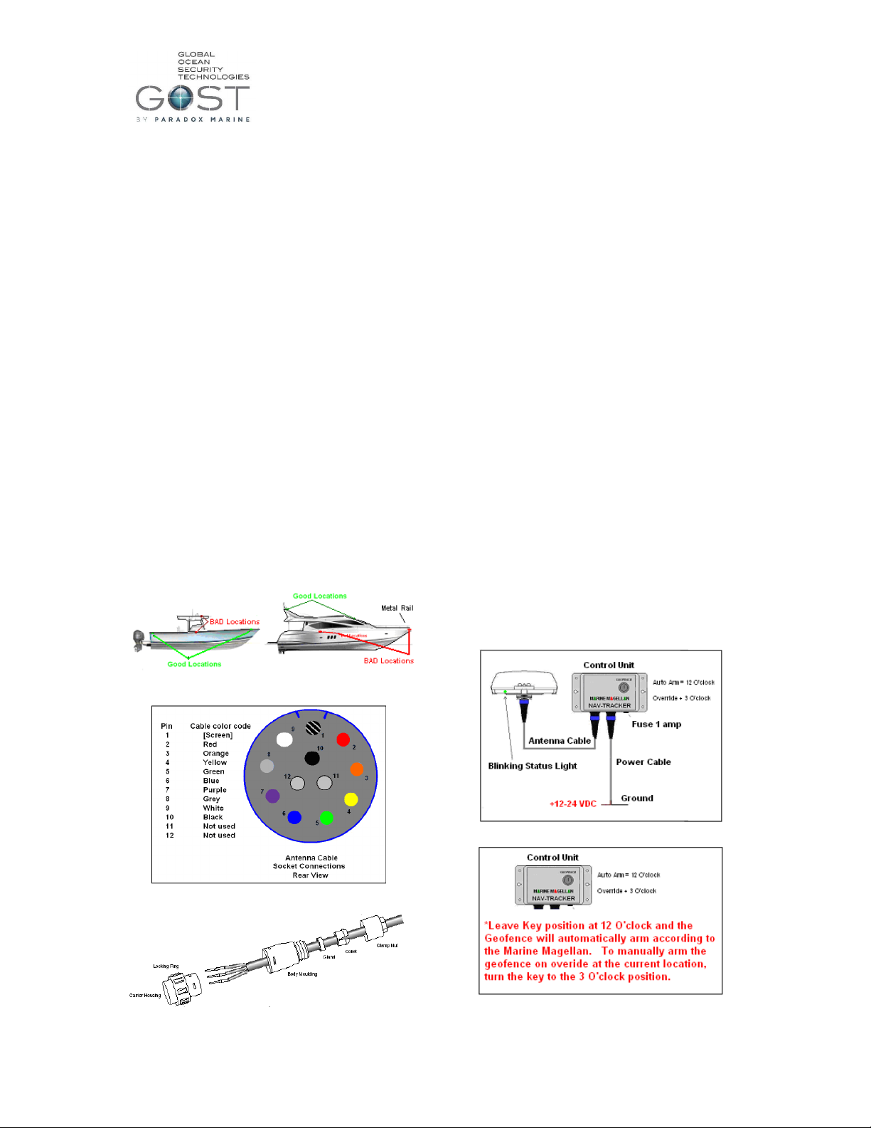
Center Consoles - It is suggested that the antenna
not be installed on T-Tops as they are more
vulnerable for tampering. Popular locations
include forward/aft stringers underneath the
gunwale. Keep away from midship gunwale
mounting as the T-Top could potentially block the
signal from getting out. Figure 1.
Larger vessels - Often require exposed hardtop or
arch mounting. A ¾ inch hole can be drilled and
sealed under the antenna with silicon. Figure 1
Whenever possible, dry run the installation
procedure and test the location beforehand. See
Installation #6
Figure 1
Figure 2
Figure 3
Voltage Requirements
The Nav-Tracker 1.0 will operate on either 12 or 24 VDC.
Power Consumption (typical@12V)
Receive 1.5W; Slotted receive 100mW; Transmit 5W
*Do not use a switched power supply that is
normally left off when the boat is idle.
Installation
1.) Thoroughly read the Nav-Tracker antenna
location considerations and mount it according to
this criteria.
2.) Snake antenna cable from antenna to the control
unit and connect the pin arraignment according to
Figure 2+ 3.
3.) Mount the control unit in a discreet and accessible
location.
4.) Connect the power cable to a constant +12-24
VDC and negative Ground. Then plug it into the
control unit.
5.) Connect Antenna connection to the antenna.
6.) There is a light at the base of the antenna Figure
4. Assure that the antenna is rotated to a position
where the light is visible to the installer. When
the unit is first powered up it will initially blink
red, then gradually change to orange, and then
green. The antenna should be blinking green
within about five minutes of startup. If it does
not, confirm that the signal is not getting blocked
and adheres to the location considerations. Make
sure that the keyswitch on the control unit is left
in the 12 O’clock AutoArm position. (Figure 5).
7.) Leave the antenna plugged in. Direct the owner
to the sticker at the bottom of the included user
guide to activate the antenna. Antennas that
remain unactivated for more than two weeks are
automatically sent a disable command. Re-enable
commands can be sent, though immediate
activation is suggested after installation.
Figure 4
Figure 5
GMM-NT - Installation Guide
Programming your GMM-NT control box to the
GOST Phantom
The GMM-NT requires the use of two of the GOST
Phantoms wireless outputs. One the backside upper right
hand corner of the control box, you will see two serial
numbers one on top of the other. Program these Serial
numbers into the GOST Phantom as described below.
1. Below the LCD screen on the GOST Phantom,
you will see three menu action buttons. Press the
one on the far right below “Menu”
2. Press the middle “Next”button until you get to
“08-System Setup”and enter the default installer
code of “1111”
3. You must now program the serial numbers of the
two outputs into the panel to initialize the
geofence and alarm notifications. Press “next”
until you get to “03-Outputs”and press “ok”.
4. Go to the next available output, (1,2,3,etc.) and
enter the first serial number on the very top right
corner (upper) on the back of the GMM-NT
Control Box. (Figure 6).
5. After you enter the last digit of the serial number,
it will say “Modify Voice Tag”, select “ok”,
Vocalize “Geofence Armed“at prompt and press
stop when done.
6. It then says “Voice Tag OK”, press “Yes”.
7. It then says “Modify Text Name”, press “next”
8. It now says “Activation Event”, press “ok”.
9. Press “next”until you see “Follow Full Arm”
10. It then asks for which Area you want it to function
with. If using only Area 1 partition on the system
simply press “next”,if using multiple partition
areas, select which area you wish it to follow.
11. It then asks “Remote Access”, press “no”
12. It then asks “Another Output”, press “yes”
13. Go to the next available output and enter the
second serial number on the very top right corner
(lower) on the back of the GMM-NT Control
Box. (Figure 6).
14. After you enter the last digit of the serial number,
it will say “Modify Voice Tag”, select “ok”,
Vocalize “In Alarm“at prompt and press stop
when done.
15. It then says “Voice Tag OK”, press “Yes”.
16. It then says “Modify Text Name”, press “next”
17. It now says “Activation Event”, press “ok”.
18. Press “next”until you see “Alarm Activation”and
then press “edit”
19. It then Says “Alarm Activation”, press “ok”
20. It then asks for which Area you want it to function
with. If using only Area 1 partition on the system
simply press “next”, if using multiple partition
areas, select which area you wish it to follow.
21. It then Says, “Steady on Alarm”, press “ok”
22. It then asks “Remote Access”, press “no”
23. It then asks “Another Output”, press “no”
24. The GMM-NT is now programmed to follow
Arm/Disarm and Alarm/Alarm Cleared events
from the GOST Phantom.
Figure 6

Popular Antenna manuals by other brands

Advantech Enterprise 120 Operation manual

Advantech

Advantech Enterprise 120 Operation manual

Kathrein CAS 180 manual

Kathrein

Kathrein CAS 180 manual

SEAS 6000 installation manual

SEAS

SEAS 6000 installation manual

Labgear 27884LAB user guide

Labgear

Labgear 27884LAB user guide

RCA ANT111Z user guide

RCA

RCA ANT111Z user guide

M2 Antenna Systems 440-11X manual

M2 Antenna Systems

M2 Antenna Systems 440-11X manual

Ubiquiti RocketDish RD-2G24 quick start guide

Ubiquiti

Ubiquiti RocketDish RD-2G24 quick start guide

TRENDnet TEW-AI75OB - 11a/g 7/5dBi Indoor Omni Directional... Specifications

TRENDnet

TRENDnet TEW-AI75OB - 11a/g 7/5dBi Indoor Omni Directional... Specifications

Audiovox FM - TERK - Radio Antenna owner's manual

Audiovox

Audiovox FM - TERK - Radio Antenna owner's manual

Ubiquiti PrismAP-5-30 quick start guide

Ubiquiti

Ubiquiti PrismAP-5-30 quick start guide

Siklu EtherHaul 8000 Series Installation, operation and maintenance manual

Siklu

Siklu EtherHaul 8000 Series Installation, operation and maintenance manual

Omron V740-BA50C24-US Operation manual

Omron

Omron V740-BA50C24-US Operation manual

Ubiquiti AF-2G24-S45 quick start guide

Ubiquiti

Ubiquiti AF-2G24-S45 quick start guide

M2 Antenna Systems 40M3L Assembly manual

M2 Antenna Systems

M2 Antenna Systems 40M3L Assembly manual

Shakespeare Electronic 2025 manual

Shakespeare Electronic

Shakespeare Electronic 2025 manual

RCA ANT705Z user guide

RCA

RCA ANT705Z user guide

Buffalo AirStation WLE-HG-NDR Specifications

Buffalo

Buffalo AirStation WLE-HG-NDR Specifications

Triax Digi 10 user guide

Triax

Triax Digi 10 user guide

manuals.online logo
manuals.online logoBrands
  • About & Mission
  • Contact us
  • Privacy Policy
  • Terms and Conditions

Copyright 2025 Manuals.Online. All Rights Reserved.