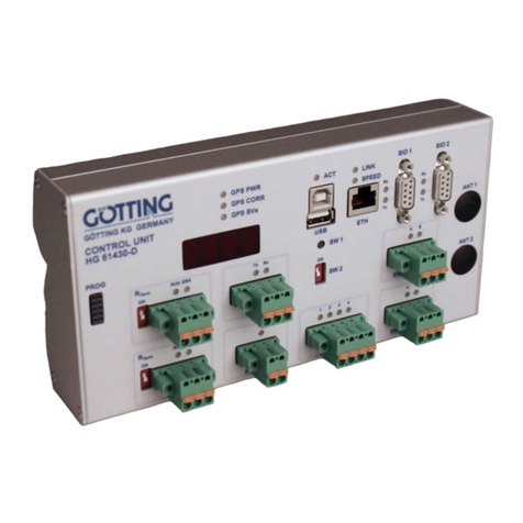
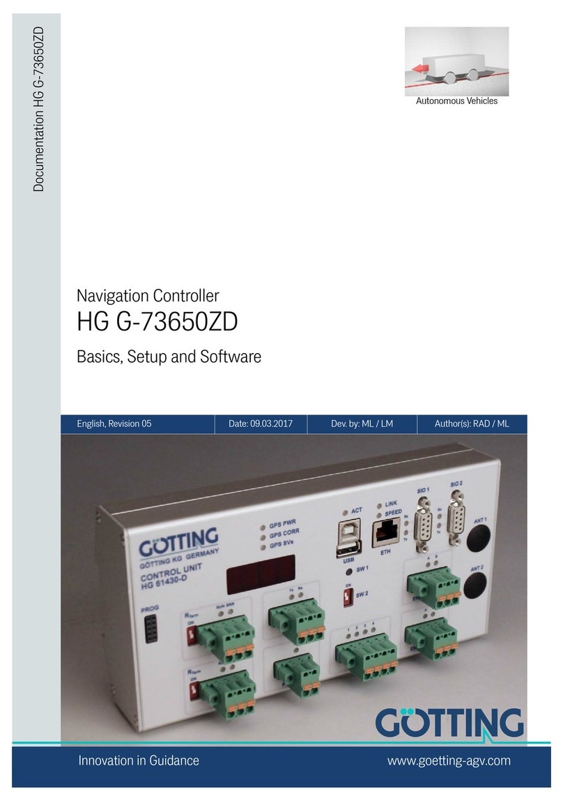
Gotting HG G-73650-A Installation guide

Contents HG G-73650-A
English, Revision 07, Date: 07.03.2018 1
Contents
1 Introduction.......................................................................4
1.1 Virtual tracks .......................................................................... 4
1.2 Suitable and unsuitable vehicle types ...................................... 5
1.3 How it works ........................................................................... 6
1.3.1 System Structure ........................................................................... 6
1.3.2 Steering Controller ........................................................................ 6
1.3.3 Sensor Fusion ...............................................................................7
1.3.4 Track Controller............................................................................. 7
1.3.5 Parameterization ........................................................................... 8
1.4 Preconditions / Options........................................................... 9
2 Guidance Control in Detail...............................................10
2.1 Steering controller ................................................................ 10
2.1.1 Segments .................................................................................... 10
2.1.1.1 The segment file ..................................................................... 11
2.1.1.2 Segment search...................................................................... 13
2.1.1.3 Specifiying the segments ........................................................ 13
2.1.1.4 Transmission of the segments................................................. 15
2.1.2 Attributes..................................................................................... 15
2.1.3 Offset driving............................................................................... 15
2.1.4 Calculation of the Steering Angle ................................................. 16
2.1.4.1 Feed Forward Control ............................................................. 17
2.1.4.2 Feed Back Control .................................................................. 17
2.1.5 Velocity Calculation ..................................................................... 18
2.1.6 Driving Modes ............................................................................. 18
2.1.6.1 Idle Mode ............................................................................... 18
2.1.6.2 Modus Parameter Test............................................................ 19
2.1.6.3 Automatic Mode ...................................................................... 19
2.1.7 Vehicle Options: Fork Lift Vehicle ................................................ 19
2.2 The Internal Sensor Fusion ................................................... 19
2.2.1 Odometric System ....................................................................... 20
2.3 Sensors for navigation .......................................................... 21
2.3.1 The Transponder Antenna ........................................................... 21
2.3.1.1 Transponder System for Positioning Calculation ...................... 21
2.3.1.2 Initialization of the Transponder Sensor Fusion ....................... 22
2.3.1.3 Transponder List..................................................................... 22
2.3.2 Sky-Trax ..................................................................................... 23
2.4 Vehicle Control Unit .............................................................. 23
3 Interfaces........................................................................25
3.1 CAN Bus .............................................................................. 25

Contents HG G-73650-A
English, Revision 07, Date: 07.03.2018 2
3.1.1 CAN 1 ......................................................................................... 25
3.1.2 CAN 2 ......................................................................................... 25
3.2 Profibus................................................................................ 26
3.3 Ethernet ............................................................................... 26
3.4 Serial Interfaces ................................................................... 26
3.4.1 SIO 1 .......................................................................................... 26
3.4.2 SIO 2 .......................................................................................... 26
3.4.3 SIO 3 .......................................................................................... 26
3.4.4 SIO 4 .......................................................................................... 27
3.5 Terminal ............................................................................... 27
3.6 IO 1 to 4 ............................................................................... 27
4 Commissioning................................................................28
4.1 Commissioning of Communication......................................... 28
4.2 Commissioning Terminal Program......................................... 29
4.2.1 Finding Hyper Terminal / Adding Hyper Terminal to the system .... 29
4.2.2 Parameter Settings ...................................................................... 30
4.3 Using the Terminal Program.................................................. 30
4.4 Main Menu ........................................................................... 31
4.5 (A) Main Monitor Navigation.................................................. 32
4.5.1 Monitor Outputs........................................................................... 32
4.5.2 Input Options............................................................................... 35
4.6 (B) Main Monitor Sensorfusion .............................................. 35
4.7 (C) Vehicle Monitor ............................................................... 39
4.8 (D) Datalogging .................................................................... 39
4.9 (E) Test Monitor.................................................................... 40
4.9.1 Display outputs............................................................................ 40
4.9.2 Input Options............................................................................... 41
4.10 (F) Error Logger.................................................................... 42
4.11 (G) Parameters Navigation.................................................... 49
4.11.1 (A) Main ...................................................................................... 50
4.11.2 (B) Geometric.............................................................................. 52
4.11.3 (C) Accuracy ............................................................................... 54
4.11.4 (D) Steering................................................................................. 55
4.11.4.1 Parameters ............................................................................. 55
4.11.4.2 Steering correction.................................................................. 56
4.11.5 (E) Stering Controller................................................................... 57
4.11.6 (F) Speed Controller .................................................................... 60
4.11.7 (G) Sensor Fusion ...................................................................... 61
4.11.8 (H) Vehicle Specials .................................................................... 63

Contents HG G-73650-A
English, Revision 07, Date: 07.03.2018 3
4.11.9 (I) Datalogging (Parameterization of the output) ........................... 63
4.12 Display and key pad of the control unit .................................. 65
4.12.1 Status output on the Display ........................................................ 65
4.12.2 Direct input options at the control unit .......................................... 67
5 Trouble Shooting.............................................................69
6 List of Images .................................................................71
7 List of Tables ..................................................................72
8 Essential Information for Reading this Manual..................74
9 Copyright and Terms of Liability ......................................75
9.1 Copyright.............................................................................. 75
9.2 Exclusion of Liability ............................................................. 75
9.3 Trade Marks and Company Names........................................ 75

Introduction HG G-73650-A
English, Revision 07, Date: 07.03.2018 4
1 Introduction
The subject of this manual is the track guidance controller for AGV (Automated Guided
Vehicles) used for following virtual tracks (see below). This manual describes the fol-
lowing components of the track guidance controller:
1. Track control with steering controller, sensor fusion and vehicle control (see
chapter 2 on page 10)
2. Overview of interfaces (see chapter 3 on page 25)
3. Commissioning (see chapter 4 on page 28)
4. The description of the hardware and the telegram listing of the interfaces can
be found in two separate documents
The following sections of the introduction will provide an overview of these areas.
1.1 Virtual tracks
A virtual track describes a route that does not have physical tracks or marks (e.g. op-
tical lines or inductive guide wires). It is usually defined in a CAD program (below we
will refer to Malz++Kassner CAD 6 for which Götting KG provides a plug-in for the track
guidance controller) where the required track is directly drawn into a layout. The vehi-
cle will follow this virtual track like on a real track or rails. The CAD software has to re-
flect the features of the vehicle used (see below) in order to make tracking as accurate
as possible.
Figure 1 Example: Virtual track with support points
The virtual track consists of several segments that define the sections between
branches and end points. Each of the segments must consist of at least four support
points which are positioned at equal distance over the whole route. These support
points are not actual points on the route (for example transponders in the ground). The
distance between them depends on the type of the route and the vehicle used. The
closer the support points lie next to one another the more precisely the tracking will
correlate with the virtual track. However, very close distances between the points are
unnecessary for large vehicles because the vehicle itself cannot drive that accurately.
Should the distances between the points be too long, the CAD software would display
them as polygonal curves because no rounded curve can be calculated from points
which are wide apart from one another.

Introduction HG G-73650-A
English, Revision 07, Date: 07.03.2018 5
1.2 Suitable and unsuitable vehicle types
The range of particularly suitable vehicle types covers all vehicles that either have a
fixed axle or symmetrical steering. Vehicles such as trucks, forklift trucks, electric tow
tractors and some heavy-duty transporters fulfill these requirements. A fixed axle can
be applied to the axis of symmetry without the problem of dragging wheels in curves.
Figure 2 Example: A selection of vehicle types
The sketch below shows simplified versions of all vehicles as three-wheelers, because
this is the base vehicle model used by the track guidance controller. For example also
a car is only steered from one point, so the computer can consider it a three-wheeler.
Both wheels on the front axle follow a specified steering angle. The track guidance
controller can also be used for vehicles where the steered wheel is not in the middle
(e.g. some fork-lift trucks).
Figure 3 Sketch: Suitable vehicle types
The further the actual vehicle diverges from the typical three-wheeler model (e.g. cen-
ter-pivot steered vehicles such as front loaders where the distance between the axles
varies when turning), the less precise the tracking will be. Omnidirectional vehicles are
also suitable, but require a different firmware than the three-wheeler models.
Fixed axle
particularly suitable
e.g. fork lift trucks
Symmetrical axle
particularly suitable
e.g. some types of
heavy-load vehicles
Two fixed axles
reduced accuracy and
partially slipping wheels
e.g. large tractors
Articulated steering with
center pivot point
less accuracy
e.g. loader
Omnidirectional
drive / Mecanum
drive
requires different
firmware

Introduction HG G-73650-A
English, Revision 07, Date: 07.03.2018 6
1.3 How it works
1.3.1 System Structure
Figure 4 System Structure
Due to the strict separation of steering controller, sensor fusion and navigation system
as well as the smart interaction with vehicle controller the track guidance controller of-
fers a high degree of flexibility and is suitable for monitoring safety-critical vehicle
components.
1.3.2 Steering Controller
The track guidance controller includes the steering controller which calculates how to
guide the vehicle from the current position to follow the track. The steering controller's
outputs are
-nominal steering angle
-nominal vehicle velocity
-various additional parameters / information

Introduction HG G-73650-A
English, Revision 07, Date: 07.03.2018 7
Some steering servos and motor controller can be directly controlled by the steering
controller so that a vehicle control unit is not required in every application. Related to
monitoring, redundancy and customized modifications to the vehicle, a vehicle
control unit (e.g. PLC) is recommended for large vehicles.
If emergency stop devices are to be used, a vehicle control unit must be used in com-
bination with the track guidance controller to ensure maximal safety.
1.3.3 Sensor Fusion
The steering controller receives information from the sensor fusion about the position.
The sensor fusion can be connected internally (preferably when navigating with tran-
sponders or Sky Trax Tags) or externally (e.g. in the case of a laser scanner). The sen-
sor fusion provides the steering controller the following data (called pose):
-position on X coordinate
-position on Y coordinate
-velocity
-angle
The sensor fusion establishes these values based on the data of the connected sen-
sors (e.g. transponder antennas, laser scanners, GPS system). If required, systems
with physical guidance tracks can be integrated (e.g. inductive guide wire, optical
guidance).
There is a selection of different odometric sensors available, such as incremental / ro-
tary encoders. Optionally the accuracy and load-dependence of the odometry can be
enhanced by using the Götting Gyro HG 84300. It is also possible to calculate the
odometry from two sources and compare their results. This way, the sensor failures
can be identified.
1.3.4 Track Controller
The task of the track guidance controller is to move the vehicle from the current posi-
tion (given by the sensor fusion) to the next support point. The controller also calcu-
lates the rest of the track along several support points (it forms what are known as
regressions) and delivers the virtual track that the vehicle can drive on.
The tracks between the support points are reconstructed with smooth functions (re-
gressions over several support points) so that a continuously controlled movement of
the vehicle is possible. The values of position, accuracy, 16 free and 16 defined bits
are stored at each support point.

Introduction HG G-73650-A
English, Revision 07, Date: 07.03.2018 8
Figure 5 Exemplary layout with travel commands as a combination of segments
The vehicle can be placed between the support points. The track controller uses the
incoming position data to identify what segment it is on and which support point fol-
lows next. The tracks to be driven on are defined from a combination of segments that
for example state where the vehicle has to turn. A travel command can be entered at
the central control unit, the vehicle control unit or directly at the steering controller.
1.3.5 Parameterization
An RS 232 interface is provided to set the parameters and to commission the vehicle.
It can be connected to a PC/ laptop with a serial interface and a terminal program.
This interface can be used to monitor and record driving conditions (e.g. for debug-
ging purposes) and to set, import or export driving parameters. Transponder and,
marker lists as well as segments can be exported, imported and displayed. This inter-
face can also be used to update the internal operating software on the track guidance
controller.
A display with a foil keyboard is integrated into the steering controller in order to enter
the segments and show status information.
Travel command:
Segments 1, 2, 3, 7

Introduction HG G-73650-A
English, Revision 07, Date: 07.03.2018 9
1.4 Preconditions / Options
-If the internal sensor fusion is to be used, at least one incremental / rotary encoder
must be used. Please ensure that this is a push/pull type with output voltage of 5
to 25 V and two tracks perpendicular to each other.
Depending on the odometry, the Gyro HG 84300 can also be used to improve
accuracy and for redundancy.
-If a transponder system is to be used, the HG S71720 system can be connected
via the CAN bus. ID 250 transponders can be used at a reading height of up to
10 cm. The Sky Trax System can be used as an alternative or in combination with
the transponder system.
-When using the HG 43600 laser scanner at least one incremental encoder must
be directly connected to the track guidance controller. If the HG S57652 GPS sys-
tem is to be used, the rotary encoders must be connected to the GPS controller.
-To extend the input and output capabilities, the IFM module CR 2033 can be con-
nected via the CAN Bus.

Guidance Control in Detail HG G-73650-A
English, Revision 07, Date: 07.03.2018 10
2 Guidance Control in Detail
The structure of the track guidance controller is shown in Figure 4 on page 6. Two in-
cremental encoderscan be connected to the steering controller hardware. This is re-
quired when:
-the internal sensor fusion is used and the steering controller has to control or mon-
itor the velocity itself or
-where a laser scanner is used.
If the internal sensor fusion is used, the position of the vehicle is calculated from the
odometry provided, initialized and adjusted by the transponder antenna and/or the
Sky-Trax system. The transponder antenna is then connected via the CAN bus. Addi-
tionally the position impulse (impulse when the midpoint of the antenna crosses the
transponder) has to be connected with IO 1. The Sky- Trax system is connected via
the SIO 3.
The optional gyro is connected via the CAN bus. Its purpose is to improve the odom-
etry. As some odometric calculations tend to be dependent on load, we recommend
the integration of the gyro.
If an external sensor fusion is to be used (to identify position and angle), it can be con-
nected to the CAN bus. The applicable protocol is specified in the reference manual
supplied.
External sensor fusions can be for example laser scanners (HG 43600) or GPS
(HG S57652). Other position identification systems can be used as long as they com-
ply with the CAN bus protocol (see reference manual).
2.1 Steering controller
The purpose of the steering controller is to guide the vehicle on the track. It needs in-
formation about which track to drive on and the current position of the vehicle. The
central control unit tells the steering controller what segment to drive on. The segments
were generated in the CAD software (see below) represented by their support points.
Using the current vehicle position and angle the relation to the segment is known. Then
the steering angle and vehicle velocity can be calculated.
2.1.1 Segments
Segments are the connecting paths between branches and end points. The routes are
compiled from these segments from the start to the finish.
Example A small area has four stations. To move the vehicle from the sta-
tion 1 to station 3, the vehicle has to pass segments 4, 5, 8 and 9.
To return to station 1 (with the same vehicle orientation), the vehi-

Guidance Control in Detail HG G-73650-A
English, Revision 07, Date: 07.03.2018 11
cle has to go through segments 10, 1, 7, 6 and 3. Since the vehi-
cle drives backwards along segments 6 and 3, the velocity of the
segments is negative (see also Figure 7 on page 12).
Figure 6 Example: Segments
2.1.1.1 The segment file
All segments and the associated support points are stored in the segment file. This
segment file is created with a CAD software (Malz ++ Kassner CAD6). The typically
large CSV file, created by the CAD software, must be compiled into a binary format
using BRTool. The BRTool software is available from us on request. BRTool also allows
you to directly edit individual support points and their critical attributes such as veloc-
ity without having access to CAD6.
Each row of the segment file represents one support point. It contains the support
point's coordinates, two velocities and an attribute field.
3;304;8920;2164;10;10;0x00000000
3;305;8920;1914;5;10;0x00000000
3;306;8920;1665;1;10;0x00000002
4;1;8920;1665;10;10;0x00000001
4;2;8920;1416;10;10;0x00000000
4;3;8920;1167;10;10;0x00000000
Segment
number Point number X Position Y Position Velocity
end
Velocity
next Attribute
3304 8920 2164 10 10 0x00000000
3305 8920 1914 510 0x00000000
3306 8920 1665 110 0x00000002
4 1 8920 1665 10 10 0x00000001
4 2 8920 1416 10 10 0x00000000
4 3 8920 1167 10 10 0x00000000
Table 1 Explanation of a segment list with support points

Guidance Control in Detail HG G-73650-A
English, Revision 07, Date: 07.03.2018 12
Each row of this table is one support point. The first column contains the segment num-
ber to which the support point belongs to. The second column contains the support
point number. Columns 3 and 4 contain the X and Y coordinates of the support point
in mm. Columns 5 and 6 contain velocity data in dm/s. There are two velocities be-
cause on the one hand a connecting segment could exist, or the vehicle is to be
stopped at the end of the segment. Therefore, where the last segment is concerned or
the vehicle changes direction column 5 is automatically selected. If a connecting seg-
ment exists column 6 is selected.
The velocities are interpolated linearly depending on the position between the support
points so that a continual velocity profile is created. Only at the end of the last segment
(or if the direction of travel changes or an error occurs) will the velocity be set to 0.
NOTE! Always allow the velocity to end with 1, because if you pick 0 the
vehicle will stop before reaching the end of the segment.
If the velocity is negative, the vehicle travels backwarts on the
segment. The vehicle always moves towards the support points
(from the start of a segment to the end). This means that when the
vehicle is first to be driven in one direction on a track and then to
be reversed (e.g. when docking on and off a ramp) there must be
two segments for the same path.
The attribute field is located in column 7. The attribute is subdivid-
ed into 16 higher an 16 lower bits. The lower bits refer to internal
functions of the guidance controller. See the reference manual for
further detail. The 16 higher bits are freely available and are
passed to the vehicle control unit.
Figure 7Example for congruent segments

Guidance Control in Detail HG G-73650-A
English, Revision 07, Date: 07.03.2018 13
Figure 8 Segment FIFO shifting register
2.1.1.2 Segment search
When the guidance of the vehicle is initialized, only one position of the vehicle is
known at first. To identify the currently drivable segments and to transmit them to the
central control unit, a segment search can be carried out. During the segment search,
the track controller tests all the segments stored for drivability. The segment search
can take several seconds depending on the number of segments. It is triggered by
setting bit 4 in byte 1 of CAN Box 0x194. The steering controller must be in "waiting"
mode (stand-by). On completion bit 5 in byte 1 in the CAN box 0x185 will be set (seg-
ment search completed). The positively found segments are transmitted as a segment
listing in box 0x195 to the vehicle control unit. If the „segment-search“-bit is set to 0,
the current segments will be transmittet in the segment list of box 0x195.
2.1.1.3 Specifiying the segments
The vehicle control unit specifies the segments to the steering controller via CAN bus.
For testing purposes, they can also be specified via a terminal program or the key-
board. To ensure that continual driving is possible, the connecting segment must al-
ways be known. Therefore the steering controller has a segment memory with eight
entries designed asa FIFO (First in First Out) shift register (see Figure 8 above). Seg-
ment 0 is the current segment. Segment 1 is the next segment. Segment 7 is the last
segment in the FIFO register: If the FIFO register does not have 8 segments, the rest
of the entries are filled up with 255 (Note: 0 is a valid segment number). If the vehicle
is finished with a segment, it is pushed out of the FIFO register and the next segments
move up.

Guidance Control in Detail HG G-73650-A
English, Revision 07, Date: 07.03.2018 14
The list will be transferred to the vehicle controller via CAN bus. The vehicle controller
can respond to the removed segment, by moving a new segment into the FIFO regis-
ter.
In this way more than 8 segments can be driven without stopping. In order to connect
the segments consecutively, the terminal position of one segment always has to be the
starting position of the next one.
Before Example:
Segment number 33 just
processed
After
FIFO Segment FIFO Segment
033 010
110 117
217 2105
3105 3255
4255 4255
5255 5255
6255 6255
7255 7255
Table 2 Example: Shifting of segments - part I
Before After
FIFO Segment FIFO Segment
010
Segment number. 55 reloaded
010
117 117
2105 2105
3255 355
4255 4255
5255 5255
6255 6255
7255 7255
Table 3 Example: Shifting of segments - part II

Guidance Control in Detail HG G-73650-A
English, Revision 07, Date: 07.03.2018 15
NOTE! In order to prevent the steering controller from reloading a seg-
ment currently being changed by the vehicle control unit (the rev-
olution period from "reading the list" to "list stored" can take one
second), never edit the next segment (FIFO register number 1).
Instead edit the segment with FIFO register number 2.
2.1.1.4 Transmission of the segments
Usually the segments will be transmitted with the CAN bus. For test purposes the seg-
ments can be entered using the keypad (membrane keyboard) or via a terminal inter-
face. For more detailed information see chapter 4 „Commissioning“ on page 28.
The steering controller receives the segments in the CAN box with the identifier 0x194.
The structure of the box is described in the reference manual. This box only contains
one element of the buffer, wich is Number of segment (LowByte) and Number
of segment (HighByte. The segment numbers will be transferred as unsigned
int (16 bit), but internally only 8 bit will be used. If a 16 bit addressing is required, there
is no need to change the communication.
To place the segment correctly into the FIFO register, the register number will be trans-
ferred as well (Position of segment number in table). The steering controller
will be called up every 50 ms. Therefore the transmission of the list takes at least 8 x
50 ms = 400 ms. This list always has to be transferred in ascending order. To prevent
double transmission within 50 ms (one message would get lost and the whole table
would be invalid) there is the toggle bit. If the vehicle controller sends a box, the status
of the first bit in byte 1 of the CAN box will be changed previously. The next box should
not be transmitted before Box 0x195 (response of the steering controller) has reached
the same status. The target segment is the last segment to reach the end of a de-
sired route. The target segment does not necessarily have to be part of the FIFO reg-
ister.
The CAN box of the answer by the steering controllerhas a similar structure. This box
indicates the current status of the segments in the steering controller.
2.1.2 Attributes
If the vehicle is driving in automatic mode, the corresponding attributes are carried out
when a certain support point is reached (e.g. turn signal, horn etc.) The 16 lower bits
have a specific predefined meaning and are transmittet. The function of these bits are
specified in the reference manual. The upper 16 bits are transmittet in CAN box 0x191
byte 5 and 6. For most attributes sufficient information is disclosed in the annex. The
only exception is offset driving.
2.1.3 Offset driving
Constantly driving on the same track can lead to a strong deformation of the surface
structure (e.g. asphalt). For some plants it is appropriate therefore to vary the route by
a few centimeters. However, the track may only be moved so far that it is still possible
to read the installed transponders. For transfer stations / end points the offset has to
be switched off.

Guidance Control in Detail HG G-73650-A
English, Revision 07, Date: 07.03.2018 16
Segment 0 in the steering controller can be used as a version number of the segment
file. Segment 1 is the transition for offset driving on the left. Segment 2 serves as a tran-
sition for offset driving on the right. Both segments have to start with the coordinates
X = 0 and Y = 0. The X direction is the longitudinal direction. The Y direction represents
the offset to the actual track.
The segments should be as short as possible. Segment 3 is the return from the left off-
set to the actual track. Segment 4 is the return from the right offset to the actual track.
Figure 9 Offset segments
The offset option will be released via the attributes "offset left" (0x00000400) and offset
right (0x00000200) in the segment. The offset will be released via CAN bus in message
0x196 byte 5 bit 2 (switching right) and bit 3 (switching left). If this attribute is canceled
while the vehicle still moves to the side, the vehicle stops with an error message.
Therefore a free attribute should mark the end of the offset track early enough to undo
the offset driving.
Figure 10 Example drive
2.1.4 Calculation of the Steering Angle
The key task of the steering controller is to keep the vehicle on the intended track. This
means that the center of the fixed axis is constantly kept on the track, e.g. the center
of the rear axis of a given three- wheeler as shown in Figure 11. This is realized with
the steering angle. It is comprised of 2 components: The feed back control / regulator

Guidance Control in Detail HG G-73650-A
English, Revision 07, Date: 07.03.2018 17
and the feed forward control. If the steering controller is correctly set, 80% of the cal-
culated steering angle results from the feed forward control (dependent on the driving
conditions). Only the remaining percentage of 20% are provided by the feed back
control / regulator.
2.1.4.1 Feed Forward Control
Figure 11 Feed forward control
The feed forward control calculates a steering angle that keeps the vehicle on the
track. If the three-wheeler described is e.g. driven on a circle, the feed forward control
calculates a steering angle, that adjusts the steered wheel tangentially towards the
track. In an ideal situation the vehicle would exactly drive around this circle.
2.1.4.2 Feed Back Control
The feed back control steers the vehicle back to the intended course. At first the error
in the vehicle position will be determined.
Figure 12 Feed back control
This error consists of two parts: The error of the angle and the lateral deviation.
The steering angle is calculated in such a way that the steering wheel points towards
a point within the intended course in front of the vehicle. The distance between this
point and the center of the rear axis consists of one fix and one variable (velocity de-
pendent) component.

Guidance Control in Detail HG G-73650-A
English, Revision 07, Date: 07.03.2018 18
If the vehicle starts moving with this calculated steering angle, the point towards which
the vehicle aims moves on. In this way the vehicle returns to its intended track without
oscillating, provided the steering velocity is sufficiently fast and the vehicle speed ad-
justed.
To ensure a reduction of the oscillation for movements under worse conditions (higher
velocities or slower steering) different parameters can be adjusted. Thus the angle at
which the vehicle returns to the intended track can be limited dependent on the cur-
rent velocity. For more detailed information see chapter 4 on page 28.
If the vehicle drives around a curve, the intended track for the controller is calculated
by the tangent at the intersection of the rear axle. The needed angle to go around the
curve is computed by an algorithm and added to the angle of the feed back control.
If the vehicle travels backwards, it is mirrored at the rear axis. Subsequently the steer-
ing angle of the mirrored front wheel is calculated and inverted.
2.1.5 Velocity Calculation
The velocity is obtained from the information of the support points. Here the velocity of
the support point just passed and the upcoming support point is interpolated. Which
of the two support point velocities ("velocity endpoint" or "velocity connection") is se-
lected will depend on whether the vehicle shall stop at the segment's end or not. Once
the direction of travel is reverted from forward to backward or vice versa, the "velocity
endpoint" is selected. Also, if the course has a sharp bend at its end or terminates
completely, the "velocity endpoint" is selected.
For some vehicles various additional protective mechanisms are integrated. If signifi-
cant lateral deviations occur or if the difference between the set and actual steering
angle is too large, the vehicle decelerates to 0,2m/s. It will only accelerate to the orig-
inal velocity if the deviation was minimized.
If an error occurs or the vehicle drives beyond the end point, the velocity is set to 0.
2.1.6 Driving Modes
During normal operation of the vehicle, two different operation modes are used. The
idle mode (see section Abschnitt 2.1.6.1) and the automatic mode (see section
2.1.6.3). In idle mode the vehicle can be operated by a driver or the segment search
can be carried out. In the automatic mode, the steering controller controls the vehicle.
The parameter test mode (see section 2.1.6.2) will only be accessed during commis-
sioning.
NOTE! All other modes are applied in test carriers / prototypes or are
applicable for demonstrations on exhibitions. They are not rele-
vant for productive systems.
2.1.6.1 Idle Mode
This mode allows to operate the vehicle manually or the vehicle control unit can initiate
a segment search.

Guidance Control in Detail HG G-73650-A
English, Revision 07, Date: 07.03.2018 19
2.1.6.2 Modus Parameter Test
This mode can only be activated if the vehicle is standing still. In this mode all basic
functions can be tested during commissioning. For this purpose the terminal program
provides a special menu where you can enter velocity and steering angle via the key-
board directly (see section 4.9 on page 40). Important characteristics including incre-
mental data as well as actual velocity and steering angle will be displayed here.
2.1.6.3 Automatic Mode
In this mode the steering controller guides the vehicle. If the vehicle shall be operated
manually (by a driver) you have to exit this mode. To access or quit this mode the user
sends a request to the controller via the interface of the vehicle control unit, the keypad
or the terminal program. It is possible to quit this mode at any time.
When requesting automatic mode, the vehicle has to fulfill the following conditions:
-the vehicle must be standing still
-the vehicle must be prepared for automatic mode
-no vehicle errors are active
-the determined position has to correspond to the given segment
-it must be possible to drive the given segment
2.1.7 Vehicle Options: Fork Lift Vehicle
The software of the steering controller offers various additional specifications for guid-
ed vehicles, such as triggering an emergency stop. The most common application is
a fork lift vehicle (stapler). Further characteristics (maximum steering angle, maximum
velocity, operation with a trailer or articulated steering) can be generated upon re-
quest. See our manual for a comprehensive list of pre-defined vehicle options.
2.2 The Internal Sensor Fusion
The internal sensor fusion calculates the position and the heading of the vehicle.
By using a short-term accurate odometric system (encoder) and the absolute tran-
sponder positioning sensor and / or Sky-Trax the advantages of both systems are com-
bined. The odometric system is initialized through the absolute position sensor and
outputs the vehicle position and vehicle heading everywhere along the track.
The inaccuracies accumulated within the system over time and distance are reset
whenever an absolute position sensor (transponder) is available. Additionally the ac-
curacies of both systems are compared and corrected proportionally.
In addition the sensor fusion outputs the velocity of the vehicle as well as the accuracy
estimation of the respective position. The accuracy estimation is based on the accu-
racy table (see manual). The table is designed in such a manner that the inaccuracy
immediately after crossing a transponder is small. That means errors grow faster relat-
ed to the distance travelled since the angle is steadily worsening as well. Thus the ac-
curacy coding declines accordingly with every meter travelled.
Table of contents
Other Gotting Controllers manuals
Popular Controllers manuals by other brands

zeeltronic
zeeltronic PSR-S01 user manual

Ingersoll-Rand
Ingersoll-Rand SS175 Series Installation and maintenance information

KELD
KELD EKT8 Series operating instructions

Wireless Devices
Wireless Devices W1710 POCSAG Airport Operation manual

HP
HP P Class 450/500/550/600/650/700/750 Specifications

FIBARO
FIBARO SWIPE FGGC-001 operating manual

Plum
Plum ecoMAX860P3-C TOUCH Installation and operating manual

Carrier
Carrier KVBCN0101CLT Installation instructions and instructions for use

National Instruments
National Instruments PXIe-8861 user manual

SoundEar
SoundEar SoundEar 3 Series manual

Omron
Omron CS1W-DRM21-V1 Instruction

Allen-Bradley
Allen-Bradley 20A Original instructions