9
Governors America Corp. © 2020 Copyright All Rights Reserved
DDM101 Dual Driver Module 6-2020-A4 PIB4134
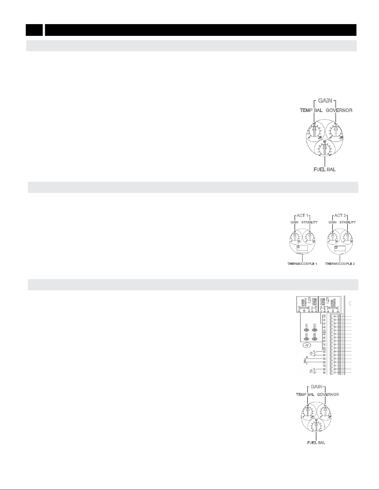
The FUEL BALANCE adjustment allows for equalization of the fuel being delivered by each
actuator. The FUEL BALANCE adjustment is set to equal engine cylinder power at near
100 % of engine load. To achieve the minimum dierence at any load point the mechanical
linkage adjustments should be set equal at 20 % power, with the electrical adjustments set equal
at 80 % power.
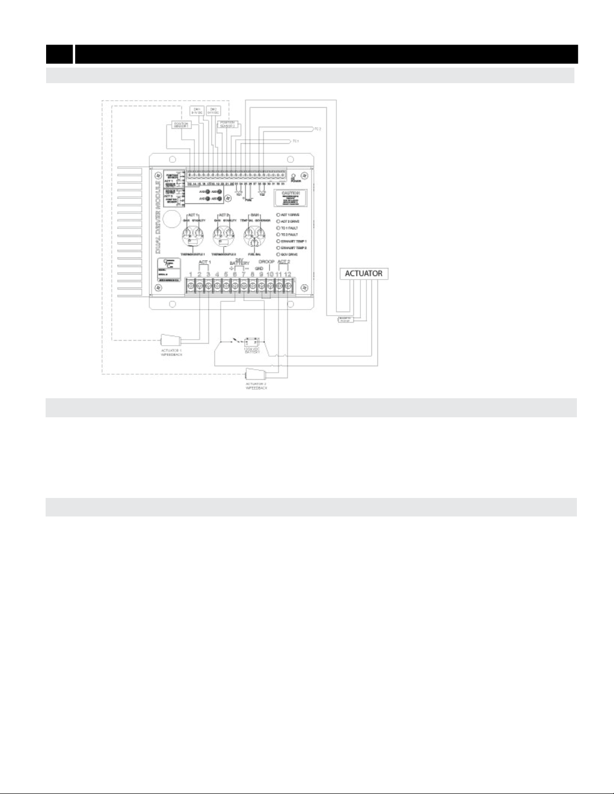
1. With the engine running at no load, using a multimeter, measure the DC voltage output of the
feedback sensors from each actuator.
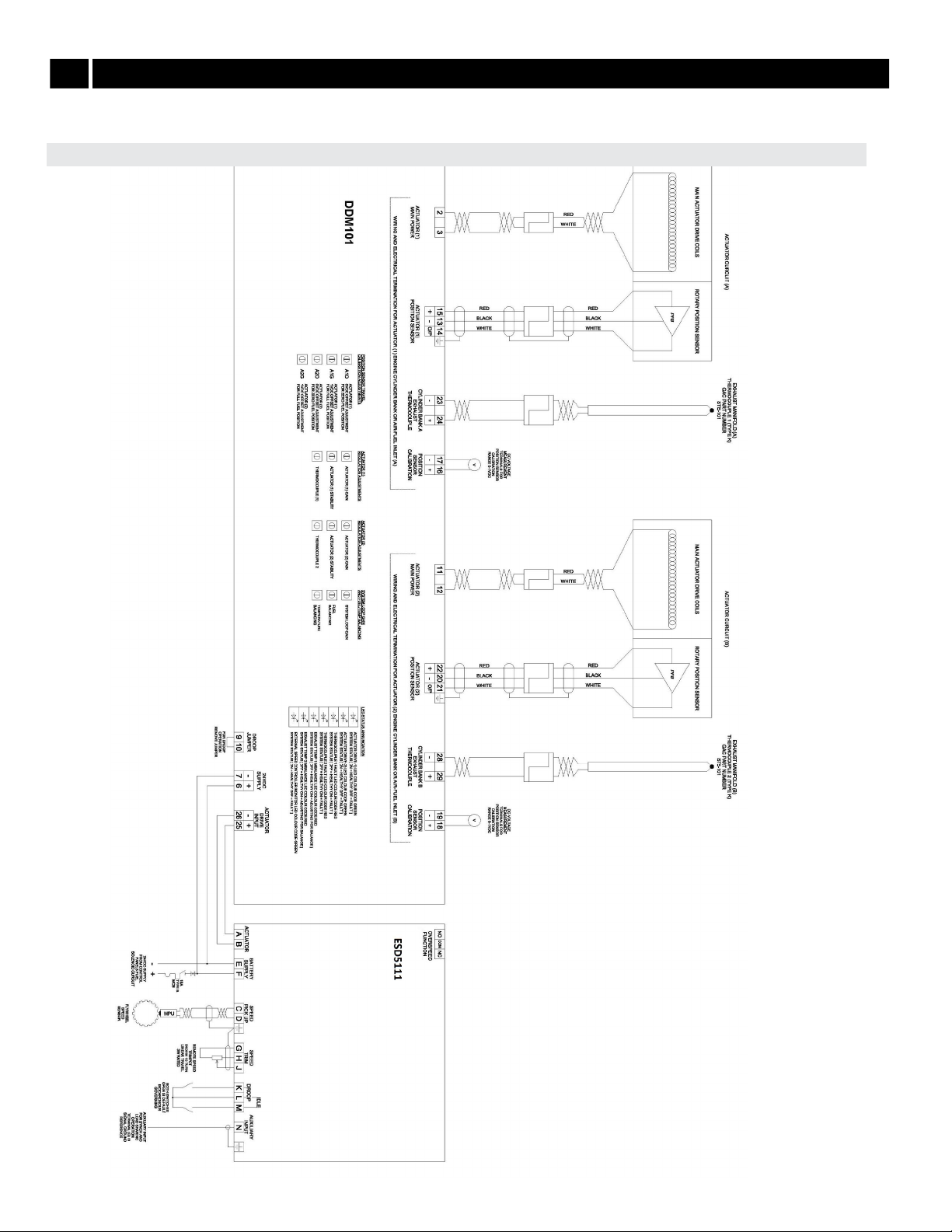
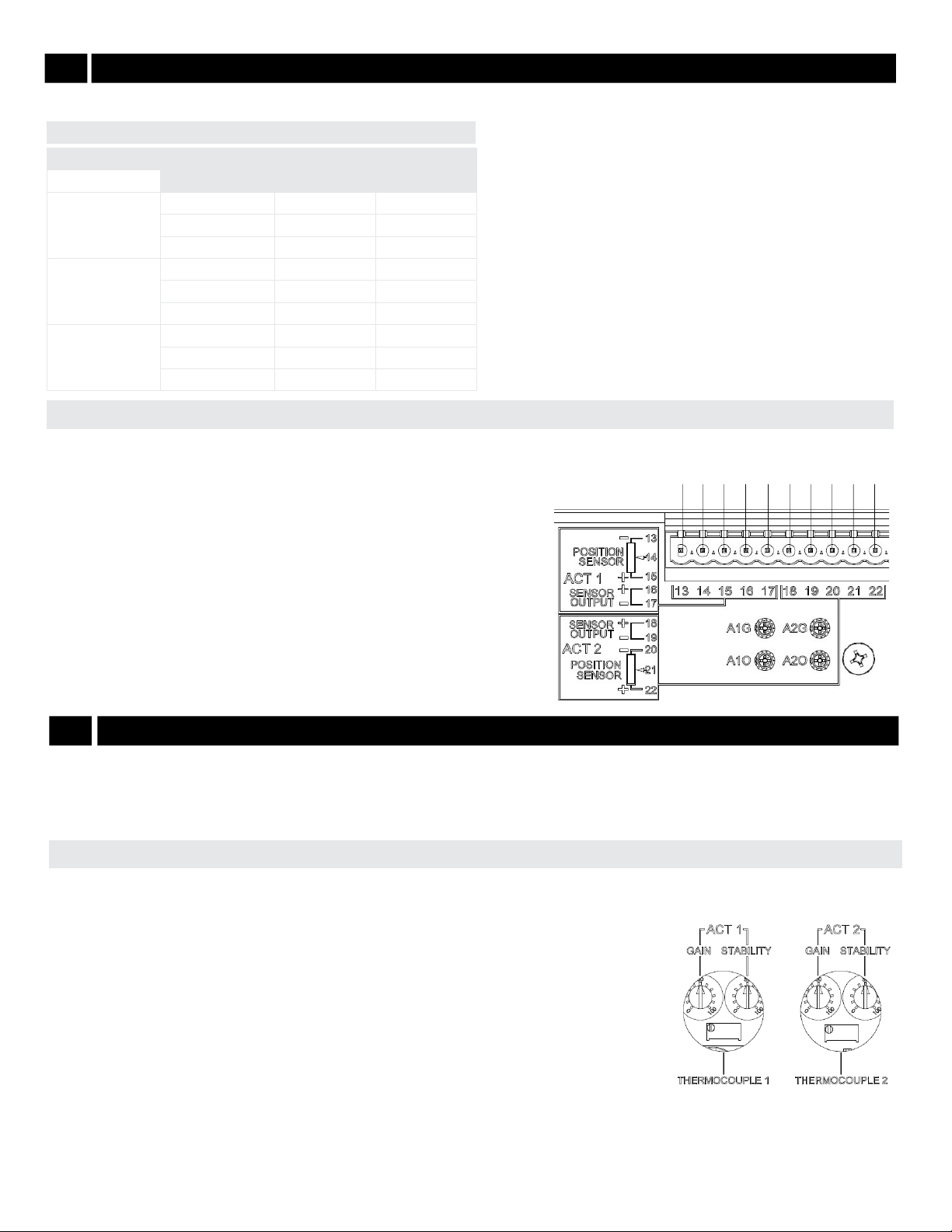
• Voltage measurement for Actuator 1 is taken across Terminals 13 and 14.
• Voltage measurement for Actuator 2 is taken across Terminals 20 and 21.
2. Both voltage measurements should have an operational range of 1 to 4 V DC.
3. If the voltage readings are not equal, adjust the FUEL BALANCE potentiometer on the
DDM101 until the voltage readings are equalized and the exhaust temperatures are
balanced.
Any dierences noted by the actuator position sensors is nullied by the electronics so that
the position sensors track equally throughout the range, unless compensated with the FUEL
BALANCE adjustment on the DDM101.
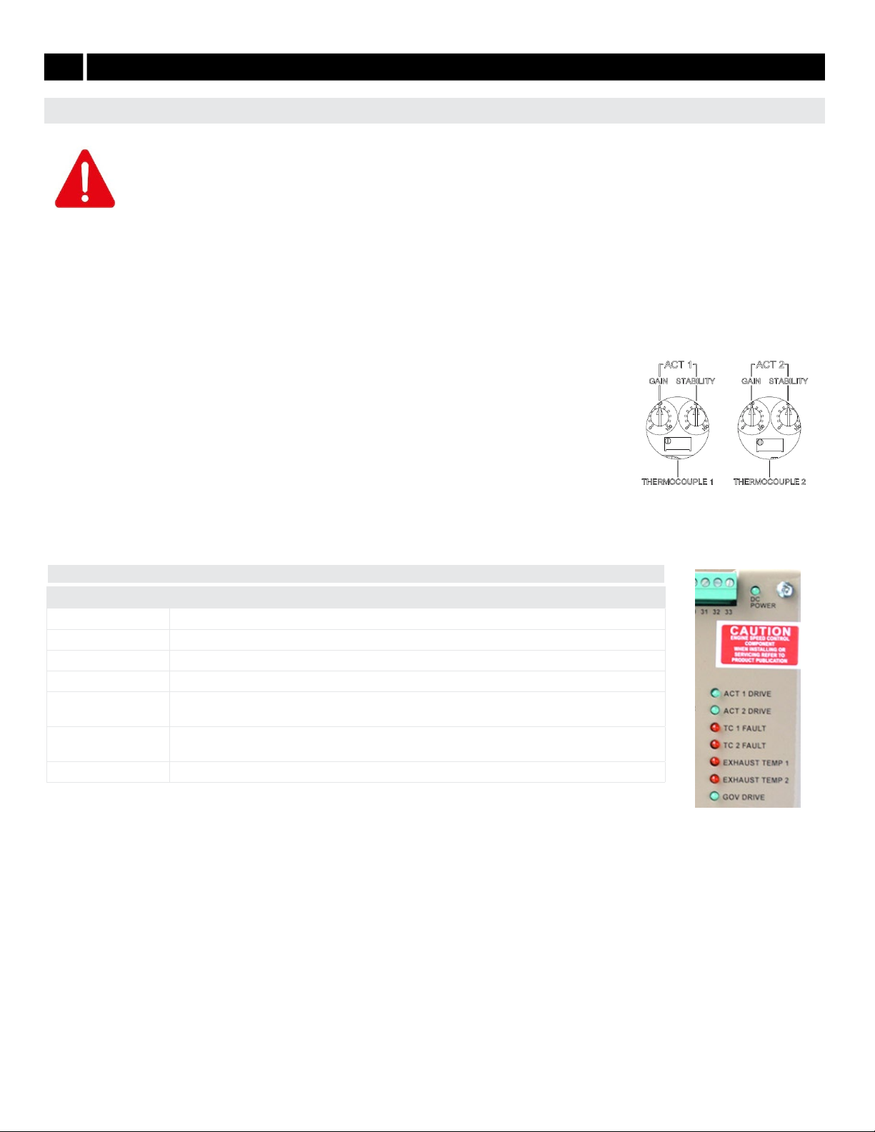
Each actuator has its own actuator stability ACT 1 STABILITY and ACT 2 STABILITY adjustment to optimize system stability. Adjust both
ACT 1 and ACT 2 STABILITY adjustments as high as possible without engine or actuator instability.
1. Adjust Actuator 1 rst by rotating the ACT 1 STABILITY adjustment CCW until instability in the
engine develops.
2. Gradually move the adjustment CW until stability returns. Move the adjustment 1/8 of a turn CW to
ensure stable performance.
3. Adjust Actuator 2 via the ACT 2 STABILITY adjustment following the same steps as for Actuator 1.
4. Poke or disturb the actuator to induce instability. Adjust the GAIN and STABILITY for best response
of the actuator.
ACTUATOR STABILITY ADJUSTMENT
FUEL BALANCE ADJUSTMENTS
With the engine running at rated speed, adjust gain and stability (PID) at the ESD or the DDM101 for optimum performance.
Adjusting the ESD, see your speed control unit’s manual for details on the following:
• For best performance, ESD gain adjustment should be set between 40 - 60 % of range.
• If the ESD GAIN adjustment is below 25 % the DDM101’s GAIN adjustment should be rotated CCW to a lower setting.
• Readjust the ESD PID settings for optimum transient performance (See your speed control unit’s
manual).
Adjusting the DDM101 can also be accomplished by analyzing the ESD PWM voltage input to Terminals 25
and 26 on the DDM101. Using a multimeter check the following:
• The voltage between Terminals 25 and 26 should measure 7 V DC at no load and 14 V DC at full load.
• If the measured voltage is lower than the desired range, the DDM101’s GAIN GOVERNOR adjustment
is set too high and should be rotated counter-clockwise to a lower setting. This should increase the
voltage across Terminals 25 and 26 on the DDM101.
• If the measured voltage is lower than the desired range, the DDM101 GAIN GOVERNOR adjustment is
set too low and should be rotated clockwise to a higher setting. The voltage across Terminals 25 and
26 on the DDM101 should decrease.
GAIN ADJUSTMENT
7ENGINE ADJUSTMENTS (CONTINUED)