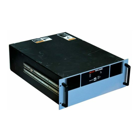
Advanced Energy HFV 8000 User manual

HFV 8000 Generator
2 MHz, 208 V Input with DeviceNet
March 2004 5705211-C User Manual


User Manual
HFV 8000 Generator
2 MHz, 208 V Input with DeviceNet
5705211-C

ii 5705211-C
Advanced Energy®
COPYRIGHT
This manual and the information contained herein is the proprietary property of
Advanced Energy Industries, Inc.
No part of this manual may be reproduced or copied without the express written
permission of Advanced Energy Industries, Inc. Any unauthorized use of this manual
or its contents is strictly prohibited. Copyright ©1997-2003 Advanced Energy
Industries, Inc. All Rights Reserved.
DISCLAIMER AND LIMITATION OF LIABILITY
The information contained in this manual is subject to change by Advanced Energy
Industries, Inc. without prior notice. Advanced Energy Industries, Inc. makes no
warranty of any kind whatsoever, either expressed or implied, with respect to the
information contained herein. Advanced Energy Industries, Inc. shall not be liable in
damages, of whatever kind, as a result of the reliance on or use of the information
contained herein.
PRODUCT USAGE STATEMENT
TRADEMARKS
Read this entire manual and all other publications pertaining to the work to be
performed before you install, operate, or maintain this equipment. Practice all plant
and product safety instructions and precautions. Failure to follow instructions can
cause personal injury and/or property damage. If the equipment is used in a manner
not specified by the manufacturer, the protection provided by the equipment may be
impaired. All personnel who work with or who are exposed to this equipment must
take precautions to protect themselves against serious or possibly fatal bodily injury.
Advanced Energy Industries, Inc., (AE) provides information on its products and
associated hazards, but it assumes no responsibility for the after-sale operation of
the equipment or the safety practices of the owner or user. This equipment produces
or uses potentially lethal high-voltage, high-current, radio frequency (RF) energy.
NEVER DEFEAT INTERLOCKS OR GROUNDS.
®is a registered trademark of Advanced Energy Industries,
Inc.
Advanced Energy®is a registered trademark of Advanced Energy Industries,
Inc.
AE®is a registered trademark of Advanced Energy Industries, Inc.

5705211-C iii
HFV 8000 Generator
CUSTOMER FEEDBACK
Advanced Energy’s technical writing staff has carefully developed this manual using
research-based document design principles. However, improvement is ongoing, and
the writing staff welcomes and appreciates customer feedback. Please send any
comments on the content, organization, or format of this user manual to:
To order a manual, please contact Technical Support:
DeviceNet™ is a trademark of Open DeviceNet Vendor Association, Inc.,
Boca Raton, FL.
SQS™is a trademark of Tru-Match Connector Corporation, Peabody, MA.

iv 5705211-C
Advanced Energy®

5705211-C v
HFV 8000 Generator
Chapter 1. Safety and Product Compliance Guidelines
Important Safety Information . . . . . . . . . . . . . . . . . . . . . . . . . . . . . . . . . . . . . . . . . 1-1
Interpreting the Manual . . . . . . . . . . . . . . . . . . . . . . . . . . . . . . . . . . . . . . . . . . . . . 1-1
Type Conventions . . . . . . . . . . . . . . . . . . . . . . . . . . . . . . . . . . . . . . . . . . . . . . 1-1
Danger, Warning, and Caution Boxes . . . . . . . . . . . . . . . . . . . . . . . . . . . . . . 1-2
Safety Guidelines . . . . . . . . . . . . . . . . . . . . . . . . . . . . . . . . . . . . . . . . . . . . . . . . . . 1-2
Rules for Safe Installation and Operation . . . . . . . . . . . . . . . . . . . . . . . . . . . . 1-2
Interpreting Product Labels . . . . . . . . . . . . . . . . . . . . . . . . . . . . . . . . . . . . . . . 1-3
Product Compliance . . . . . . . . . . . . . . . . . . . . . . . . . . . . . . . . . . . . . . . . . . . . . . . . 1-4
Product Certification . . . . . . . . . . . . . . . . . . . . . . . . . . . . . . . . . . . . . . . . . . . . 1-4
Safety and Compliance Directives and Standards . . . . . . . . . . . . . . . . . . . . . 1-5
Electromagnetic Compatibility (EMC) Directives and Standards . . . . . . . 1-5
Safety Directives and standards . . . . . . . . . . . . . . . . . . . . . . . . . . . . . . . 1-5
Industry Guidelines . . . . . . . . . . . . . . . . . . . . . . . . . . . . . . . . . . . . . . . . . 1-6
Conditions of Use . . . . . . . . . . . . . . . . . . . . . . . . . . . . . . . . . . . . . . . . . . . . . . 1-6
Interlocks . . . . . . . . . . . . . . . . . . . . . . . . . . . . . . . . . . . . . . . . . . . . . . . . . . . . . . . . 1-6
Chapter 2. Product Overview and Theory
General Description . . . . . . . . . . . . . . . . . . . . . . . . . . . . . . . . . . . . . . . . . . . . . . . . 2-1
Theory of Operation . . . . . . . . . . . . . . . . . . . . . . . . . . . . . . . . . . . . . . . . . . . . . . . . 2-2
Chapter 3. Product Specifications
Functional Specifications . . . . . . . . . . . . . . . . . . . . . . . . . . . . . . . . . . . . . . . . . . . . 3-1
Physical Specifications . . . . . . . . . . . . . . . . . . . . . . . . . . . . . . . . . . . . . . . . . . . . . 3-3
Electrical Specifications . . . . . . . . . . . . . . . . . . . . . . . . . . . . . . . . . . . . . . . . . . . . . 3-5
Environmental Specifications . . . . . . . . . . . . . . . . . . . . . . . . . . . . . . . . . . . . . . . . . 3-8
Chapter 4. Communication Interfaces
Generator User Port (15-Pin) . . . . . . . . . . . . . . . . . . . . . . . . . . . . . . . . . . . . . . . . . 4-1
Satisfying DeviceNet™ Minimum Requirements . . . . . . . . . . . . . . . . . . . . . . 4-1
User Port Interface Cabling Requirements . . . . . . . . . . . . . . . . . . . . . . . . . . . 4-2
Generator User Port Pin Descriptions . . . . . . . . . . . . . . . . . . . . . . . . . . . . . . . 4-2
Interconnect Schematics . . . . . . . . . . . . . . . . . . . . . . . . . . . . . . . . . . . . . . . . . . . . 4-7
Serial I/O Host Port (RS-232 With AE Bus) . . . . . . . . . . . . . . . . . . . . . . . . . . . . . . 4-9
Host Connector and Pin Descriptions . . . . . . . . . . . . . . . . . . . . . . . . . . . . . . 4-10
Host Port Settings . . . . . . . . . . . . . . . . . . . . . . . . . . . . . . . . . . . . . . . . . . . . . 4-11
Table of Contents

vi 5705211-C
Advanced Energy®
AE Bus (Host) Port Transmission Parameters . . . . . . . . . . . . . . . . . . . . . . . 4-12
AE Bus Protocol . . . . . . . . . . . . . . . . . . . . . . . . . . . . . . . . . . . . . . . . . . . . . . 4-13
AE Bus Header Byte . . . . . . . . . . . . . . . . . . . . . . . . . . . . . . . . . . . . . . . 4-14
AE Bus Command Number Byte . . . . . . . . . . . . . . . . . . . . . . . . . . . . . . 4-14
AE Bus Optional Length Byte . . . . . . . . . . . . . . . . . . . . . . . . . . . . . . . . 4-14
AE Bus Data Bytes . . . . . . . . . . . . . . . . . . . . . . . . . . . . . . . . . . . . . . . . 4-14
AE Bus Checksum Byte . . . . . . . . . . . . . . . . . . . . . . . . . . . . . . . . . . . . . 4-15
Creating an Ideal Communications Transaction . . . . . . . . . . . . . . . . . . . . . . 4-15
T0: Host Transmits Message Packet . . . . . . . . . . . . . . . . . . . . . . . . . . . 4-16
T1: Unit Verifies Host Transmission Packet . . . . . . . . . . . . . . . . . . . . . 4-16
T2: Unit Transmits Response to Host . . . . . . . . . . . . . . . . . . . . . . . . . . 4-16
T3: Host Acknowledges Unit Response . . . . . . . . . . . . . . . . . . . . . . . . 4-17
AE Bus Communications Transaction Example . . . . . . . . . . . . . . . . . . 4-17
AE Bus Commands . . . . . . . . . . . . . . . . . . . . . . . . . . . . . . . . . . . . . . . . . . . 4-17
AE Bus Command Status Response (CSR) Codes . . . . . . . . . . . . . . . 4-18
AE Bus Command Set . . . . . . . . . . . . . . . . . . . . . . . . . . . . . . . . . . . . . . 4-18
DeviceNet™ Port . . . . . . . . . . . . . . . . . . . . . . . . . . . . . . . . . . . . . . . . . . . . . . . . . 4-37
DeviceNet™ Control Panel . . . . . . . . . . . . . . . . . . . . . . . . . . . . . . . . . . . . . . 4-38
Control Panel LEDs . . . . . . . . . . . . . . . . . . . . . . . . . . . . . . . . . . . . . . . . 4-39
Control Panel Rotary Switches . . . . . . . . . . . . . . . . . . . . . . . . . . . . . . . 4-41
DeviceNet™ Interface Information and Supported Features . . . . . . . . . . . . 4-41
DeviceNet™ Message Types . . . . . . . . . . . . . . . . . . . . . . . . . . . . . . . . 4-42
DeviceNet™ Class Services . . . . . . . . . . . . . . . . . . . . . . . . . . . . . . . . . 4-42
DeviceNet™ Object Classes . . . . . . . . . . . . . . . . . . . . . . . . . . . . . . . . . 4-43
DeviceNet™ Data Types . . . . . . . . . . . . . . . . . . . . . . . . . . . . . . . . . . . . 4-43
Identity Object—Class Code: 01 (0x01) . . . . . . . . . . . . . . . . . . . . . . . . 4-43
Router Object—Class Code: 02 (0x02) . . . . . . . . . . . . . . . . . . . . . . . . . 4-45
DeviceNet™ Object—Class Code: 03 (0x03) . . . . . . . . . . . . . . . . . . . . 4-46
Assembly Object—Class Code: 04 (0x04) . . . . . . . . . . . . . . . . . . . . . . 4-47
Connection Object—Class Code: 05 (0x05) . . . . . . . . . . . . . . . . . . . . . 4-49
Application Object—Class Code: 64 (0x40) . . . . . . . . . . . . . . . . . . . . . 4-51
DeviceNet™ Operation . . . . . . . . . . . . . . . . . . . . . . . . . . . . . . . . . . . . . . . . . 4-53
Adding The HFV generator to a DeviceNet™ Network . . . . . . . . . . . . . 4-54
DeviceNet™ Messaging (Poll and Explicit commands) . . . . . . . . . . . . . 4-54
Poll Command and Poll Response Messages . . . . . . . . . . . . . . . . . . . . 4-54
Explicit Messaging . . . . . . . . . . . . . . . . . . . . . . . . . . . . . . . . . . . . . . . . . 4-57
Chapter 5. Installation, Setup, and Operation
Preparing to Install the HFV generator . . . . . . . . . . . . . . . . . . . . . . . . . . . . . . . . . 5-1
Spacing Requirements . . . . . . . . . . . . . . . . . . . . . . . . . . . . . . . . . . . . . . . . . . 5-1
Installation Requirements . . . . . . . . . . . . . . . . . . . . . . . . . . . . . . . . . . . . . . . . 5-1
Unpacking . . . . . . . . . . . . . . . . . . . . . . . . . . . . . . . . . . . . . . . . . . . . . . . . . . . . 5-2
Installing the HFV generator . . . . . . . . . . . . . . . . . . . . . . . . . . . . . . . . . . . . . . . . . 5-2
Front Panel Drawing . . . . . . . . . . . . . . . . . . . . . . . . . . . . . . . . . . . . . . . . . . . . 5-3
Rear Panel Drawing . . . . . . . . . . . . . . . . . . . . . . . . . . . . . . . . . . . . . . . . . . . . 5-4
Electromagnetic Field (EMF) Shielding Requirements . . . . . . . . . . . . . . . . . . 5-5

5705211-C vii
HFV 8000 Generator
Grounding . . . . . . . . . . . . . . . . . . . . . . . . . . . . . . . . . . . . . . . . . . . . . . . . . . . . 5-5
Connecting Cooling Water . . . . . . . . . . . . . . . . . . . . . . . . . . . . . . . . . . . . . . . 5-5
Connecting I/O and Auxiliary Connectors . . . . . . . . . . . . . . . . . . . . . . . . . . . . 5-6
Connecting Output Power . . . . . . . . . . . . . . . . . . . . . . . . . . . . . . . . . . . . . . . . 5-7
Connecting Input Power . . . . . . . . . . . . . . . . . . . . . . . . . . . . . . . . . . . . . . . . . 5-7
First-Time Operation . . . . . . . . . . . . . . . . . . . . . . . . . . . . . . . . . . . . . . . . . . . . . . . 5-8
Before Engaging the Rear Circuit Breaker . . . . . . . . . . . . . . . . . . . . . . . . . . . 5-9
Before Enabling the Output . . . . . . . . . . . . . . . . . . . . . . . . . . . . . . . . . . . . . . . 5-9
Enabling the Output . . . . . . . . . . . . . . . . . . . . . . . . . . . . . . . . . . . . . . . . . . . . 5-9
Meeting Minimum Power Threshold . . . . . . . . . . . . . . . . . . . . . . . . . . . . . . . 5-11
Setting the Frequency Band . . . . . . . . . . . . . . . . . . . . . . . . . . . . . . . . . . . . . 5-11
Normal Operation . . . . . . . . . . . . . . . . . . . . . . . . . . . . . . . . . . . . . . . . . . . . . . . . . 5-12
Center Frequency Mode . . . . . . . . . . . . . . . . . . . . . . . . . . . . . . . . . . . . . . . . 5-12
Selecting Center Frequency Mode . . . . . . . . . . . . . . . . . . . . . . . . . . . . 5-12
Automatic Tuning Mode . . . . . . . . . . . . . . . . . . . . . . . . . . . . . . . . . . . . . . . . 5-13
Selecting Automatic Tuning Mode . . . . . . . . . . . . . . . . . . . . . . . . . . . . . 5-13
Adjusting Tuning Parameters . . . . . . . . . . . . . . . . . . . . . . . . . . . . . . . . . 5-14
Display Mode and the LCD Display Indicator . . . . . . . . . . . . . . . . . . . . . . . . 5-16
Monitoring the Generator . . . . . . . . . . . . . . . . . . . . . . . . . . . . . . . . . . . . . . . . . . . 5-17
Running Internal Diagnostics . . . . . . . . . . . . . . . . . . . . . . . . . . . . . . . . . . . . . . . . 5-18
Chapter 6. Troubleshooting and Global Customer
Support
Before Calling AE Global Customer Support . . . . . . . . . . . . . . . . . . . . . . . . . . . . . 6-1
Troubleshooting Guide . . . . . . . . . . . . . . . . . . . . . . . . . . . . . . . . . . . . . . . . . . 6-1
Error Indications . . . . . . . . . . . . . . . . . . . . . . . . . . . . . . . . . . . . . . . . . . . . . . . . . . . 6-2
Front Panel Display (LCD) Not Lit . . . . . . . . . . . . . . . . . . . . . . . . . . . . . . . . . . 6-2
Advanced Energy Displayed on LCD . . . . . . . . . . . . . . . . . . . . . . . . . . . . . . . 6-2
Fault Indicator On . . . . . . . . . . . . . . . . . . . . . . . . . . . . . . . . . . . . . . . . . . . . . . 6-3
Overtemperature Fault . . . . . . . . . . . . . . . . . . . . . . . . . . . . . . . . . . . . . . . 6-3
RF Enable Without Interlock Fault . . . . . . . . . . . . . . . . . . . . . . . . . . . . . . 6-3
Input Line Fault . . . . . . . . . . . . . . . . . . . . . . . . . . . . . . . . . . . . . . . . . . . . 6-3
Bad Cal EEPROM Fault . . . . . . . . . . . . . . . . . . . . . . . . . . . . . . . . . . . . . . 6-4
DeviceNet Faults . . . . . . . . . . . . . . . . . . . . . . . . . . . . . . . . . . . . . . . . . . . 6-4
Interlock OK Indicator Off . . . . . . . . . . . . . . . . . . . . . . . . . . . . . . . . . . . . . . . . 6-5
What is the Interlock? . . . . . . . . . . . . . . . . . . . . . . . . . . . . . . . . . . . . . . . 6-5
Load Regulation Indicator Flashing . . . . . . . . . . . . . . . . . . . . . . . . . . . . . . . . 6-5
RF On Indicator Off . . . . . . . . . . . . . . . . . . . . . . . . . . . . . . . . . . . . . . . . . . . . . 6-6
At Set Point Indicator Off . . . . . . . . . . . . . . . . . . . . . . . . . . . . . . . . . . . . . . . . 6-7
Internal Fault Check . . . . . . . . . . . . . . . . . . . . . . . . . . . . . . . . . . . . . . . . . 6-7
External Load Checks - Open/Short RF Output Path . . . . . . . . . . . . . . . 6-7
No Output / No Plasma . . . . . . . . . . . . . . . . . . . . . . . . . . . . . . . . . . . . . . . . . . 6-8
High Reflected Power . . . . . . . . . . . . . . . . . . . . . . . . . . . . . . . . . . . . . . . . . . . 6-8
AE World Wide Web Site . . . . . . . . . . . . . . . . . . . . . . . . . . . . . . . . . . . . . . . . . . . . 6-9
AE Global Customer Support . . . . . . . . . . . . . . . . . . . . . . . . . . . . . . . . . . . . . . . . 6-10

viii 5705211-C
Advanced Energy®
Returning Units for Repair . . . . . . . . . . . . . . . . . . . . . . . . . . . . . . . . . . . . . . . . . . 6-11
Warranty . . . . . . . . . . . . . . . . . . . . . . . . . . . . . . . . . . . . . . . . . . . . . . . . . . . . . . . 6-12
Authorized Returns . . . . . . . . . . . . . . . . . . . . . . . . . . . . . . . . . . . . . . . . . . . . 6-12
Warranty Statement . . . . . . . . . . . . . . . . . . . . . . . . . . . . . . . . . . . . . . . . . . . 6-13

5705211-C ix
HFV 8000 Generator
Table 1-1. Electromagnetic compatibility (EMC) directives and standards . . . . . . . . . . 1-5
Table 1-2. Safety directives and standards . . . . . . . . . . . . . . . . . . . . . . . . . . . . . . . . . . 1-5
Table 1-3. Industry guidelines . . . . . . . . . . . . . . . . . . . . . . . . . . . . . . . . . . . . . . . . . . . . 1-6
Table 1-4. Hardware interlocks . . . . . . . . . . . . . . . . . . . . . . . . . . . . . . . . . . . . . . . . . . . 1-7
Table 2-1. HFV generator theory of operation . . . . . . . . . . . . . . . . . . . . . . . . . . . . . . . 2-2
Table 3-1. Functional specifications . . . . . . . . . . . . . . . . . . . . . . . . . . . . . . . . . . . . . . . 3-1
Table 3-2. Physical specifications . . . . . . . . . . . . . . . . . . . . . . . . . . . . . . . . . . . . . . . . . 3-5
Table 3-3. Electrical specifications . . . . . . . . . . . . . . . . . . . . . . . . . . . . . . . . . . . . . . . . 3-5
Table 3-4. Climatic specifications . . . . . . . . . . . . . . . . . . . . . . . . . . . . . . . . . . . . . . . . . 3-8
Table 3-5. Environmental specifications . . . . . . . . . . . . . . . . . . . . . . . . . . . . . . . . . . . . 3-8
Table 4-1. Generator User port pin descriptions . . . . . . . . . . . . . . . . . . . . . . . . . . . . . . 4-2
Table 4-2. Host port connector . . . . . . . . . . . . . . . . . . . . . . . . . . . . . . . . . . . . . . . . . . 4-10
Table 4-3. Host port settings . . . . . . . . . . . . . . . . . . . . . . . . . . . . . . . . . . . . . . . . . . . . 4-11
Table 4-4. Baud rate for Host port . . . . . . . . . . . . . . . . . . . . . . . . . . . . . . . . . . . . . . . . 4-12
Table 4-5. Transmission parameters . . . . . . . . . . . . . . . . . . . . . . . . . . . . . . . . . . . . . 4-12
Table 4-6. Command Status Response (CSR) codes . . . . . . . . . . . . . . . . . . . . . . . . 4-18
Table 4-7. Host port commands . . . . . . . . . . . . . . . . . . . . . . . . . . . . . . . . . . . . . . . . . 4-20
Table 4-8. DeviceNet™ pin descriptions . . . . . . . . . . . . . . . . . . . . . . . . . . . . . . . . . . . 4-38
Table 4-9. Module status (MOD) LED . . . . . . . . . . . . . . . . . . . . . . . . . . . . . . . . . . . . . 4-39
Table 4-10. Network status (NET) LED . . . . . . . . . . . . . . . . . . . . . . . . . . . . . . . . . . . . 4-40
Table 4-11. DeviceNet™ supported message types . . . . . . . . . . . . . . . . . . . . . . . . . . 4-42
Table 4-12. DeviceNet™ supported class services . . . . . . . . . . . . . . . . . . . . . . . . . . 4-42
Table 4-13. DeviceNet™ supported object classes . . . . . . . . . . . . . . . . . . . . . . . . . . 4-43
Table 4-14. DeviceNet data types . . . . . . . . . . . . . . . . . . . . . . . . . . . . . . . . . . . . . . . . 4-43
Table 4-15. Identity object class attributes . . . . . . . . . . . . . . . . . . . . . . . . . . . . . . . . . 4-44
Table 4-16. Identity object instance attributes . . . . . . . . . . . . . . . . . . . . . . . . . . . . . . . 4-44
Table 4-17. Identity object common services . . . . . . . . . . . . . . . . . . . . . . . . . . . . . . . 4-45
Table 4-18. Router object class attributes . . . . . . . . . . . . . . . . . . . . . . . . . . . . . . . . . . 4-45
Table 4-19. Router object instance 1 attributes . . . . . . . . . . . . . . . . . . . . . . . . . . . . . 4-45
Table 4-21. DeviceNet™ object class attributes . . . . . . . . . . . . . . . . . . . . . . . . . . . . . 4-46
Table 4-22. DeviceNet™ object instance 1 attributes . . . . . . . . . . . . . . . . . . . . . . . . . 4-46
Table 4-20. Router object common services . . . . . . . . . . . . . . . . . . . . . . . . . . . . . . . . 4-46
Table 4-23. DeviceNet™ object common services . . . . . . . . . . . . . . . . . . . . . . . . . . . 4-47
Table 4-24. Assembly object class attributes . . . . . . . . . . . . . . . . . . . . . . . . . . . . . . . 4-47
Table 4-25. Assembly object instance 100 attributes . . . . . . . . . . . . . . . . . . . . . . . . . 4-48
Table 4-26. Assembly object instance 101 attributes . . . . . . . . . . . . . . . . . . . . . . . . . 4-48
Table 4-27. Assembly object common services . . . . . . . . . . . . . . . . . . . . . . . . . . . . . 4-49
Table 4-28. Connection object class attributes . . . . . . . . . . . . . . . . . . . . . . . . . . . . . . 4-49
Table 4-29. Connection object instance 1 attributes (explicit message) . . . . . . . . . . . 4-49
Table 4-30. Connection object instance 2 attributes (poll message) . . . . . . . . . . . . . 4-50
Table 4-31. Connection object common services . . . . . . . . . . . . . . . . . . . . . . . . . . . . 4-51
Table 4-32. Application object class attributes . . . . . . . . . . . . . . . . . . . . . . . . . . . . . . 4-52
List of Tables

x5705211-C
Advanced Energy®
Table 4-33. Application object instance 1 attributes . . . . . . . . . . . . . . . . . . . . . . . . . . 4-52
Table 4-34. Application object common services . . . . . . . . . . . . . . . . . . . . . . . . . . . . 4-52
Table 4-35. Structure of the poll command message . . . . . . . . . . . . . . . . . . . . . . . . . 4-54
Table 4-36. Poll response message . . . . . . . . . . . . . . . . . . . . . . . . . . . . . . . . . . . . . . 4-55
Table 4-37. DeviceNet voltage ranges . . . . . . . . . . . . . . . . . . . . . . . . . . . . . . . . . . . . 4-56
Table 5-1. Frequency values in center frequency mode . . . . . . . . . . . . . . . . . . . . . . . 5-11
Table 5-2. Indicators . . . . . . . . . . . . . . . . . . . . . . . . . . . . . . . . . . . . . . . . . . . . . . . . . . 5-17
Table 6-1. Global Customer Support locations . . . . . . . . . . . . . . . . . . . . . . . . . . . . . . 6-10

5705211-C xi
HFV 8000 Generator
Figure 1-1. Interlock circuit . . . . . . . . . . . . . . . . . . . . . . . . . . . . . . . . . . . . . . . . . . . . . . 1-7
Figure 2-1. HFV generator block diagram . . . . . . . . . . . . . . . . . . . . . . . . . . . . . . . . . . . 2-2
Figure 3-1. Mounting dimensions (shown without optional water solenoid) . . . . . . . . . 3-4
Figure 4-1. Generator User port connector . . . . . . . . . . . . . . . . . . . . . . . . . . . . . . . . . . 4-1
Figure 4-2. Reflected power . . . . . . . . . . . . . . . . . . . . . . . . . . . . . . . . . . . . . . . . . . . . . 4-7
Figure 4-3. Forward/load power output . . . . . . . . . . . . . . . . . . . . . . . . . . . . . . . . . . . . . 4-7
Figure 4-4. RF power enable . . . . . . . . . . . . . . . . . . . . . . . . . . . . . . . . . . . . . . . . . . . . 4-8
Figure 4-5. Forward/load power set point . . . . . . . . . . . . . . . . . . . . . . . . . . . . . . . . . . . 4-8
Figure 4-6. RF power on status . . . . . . . . . . . . . . . . . . . . . . . . . . . . . . . . . . . . . . . . . . . 4-9
Figure 4-7. Interlock loop . . . . . . . . . . . . . . . . . . . . . . . . . . . . . . . . . . . . . . . . . . . . . . . 4-9
Figure 4-8. Serial AE Bus Host port connector . . . . . . . . . . . . . . . . . . . . . . . . . . . . . . 4-10
Figure 4-9. Graphic representation of a message packet . . . . . . . . . . . . . . . . . . . . . . 4-13
Figure 4-10. AE Bus communications transaction . . . . . . . . . . . . . . . . . . . . . . . . . . . 4-15
Figure 4-11. Communications transaction example . . . . . . . . . . . . . . . . . . . . . . . . . . 4-17
Figure 4-12. DeviceNet™ connector . . . . . . . . . . . . . . . . . . . . . . . . . . . . . . . . . . . . . . 4-38
Figure 4-13. DeviceNet™ control panel . . . . . . . . . . . . . . . . . . . . . . . . . . . . . . . . . . . 4-38
Figure 5-1. Front view . . . . . . . . . . . . . . . . . . . . . . . . . . . . . . . . . . . . . . . . . . . . . . . . . . 5-3
Figure 5-2. Rear view (shown with optional water solenoid) . . . . . . . . . . . . . . . . . . . . . 5-4
List of Figures

xii 5705211-C
Advanced Energy®

5705211-C Safety and Product Compliance Guidelines 1-1
Chapter
HFV 8000 Generator Chapter
1
Safety and Product Compliance
Guidelines
IMPORTANT SAFETY INFORMATION
To ensure safe installation and operation of the Advanced Energy®HFV generator,
read and understand this manual before attempting to install and operate this unit. At a
minimum, read and follow the safety instructions and practices documented under
“Safety Guidelines” on page 1-2.
INTERPRETING THE MANUAL
The following sections explain the document type conventions and the danger,
warning, and caution boxes that provide information about the specific levels of
hazard seriousness.
Type Conventions
Please note the following type conventions:
•Pin(2) and signal names (REFLECTED POWER OUTPUT) appear in capitalized
italics.
• Technical terms appear in italicized text when first introduced, and many terms
are defined in the Glossary.
• Unit labels (switches, indicators, and so forth) generally appear in boldface letters
as they are labeled on the unit (Standby).
• Commands (5) and command names (starting frequency) appear in boldface
lowercase letters.

1-2 Safety and Product Compliance Guidelines 5705211-C
Advanced Energy®
Danger, Warning, and Caution Boxes
This symbol represents important notes concerning potential harm to people, this unit,
or associated equipment. Advanced Energy®includes this symbol in Danger,
Warning, and Caution boxes to identify specific levels of hazard seriousness.
SAFETY GUIDELINES
Review the following information before attempting to install and operate the product.
Rules for Safe Installation and Operation
Please note the following rules for safe installation and operation of the product.
• Do not attempt to install or operate this equipment without proper training.
• Ensure that this unit is properly grounded.
• Ensure that all cables are properly connected.
• Verify that input line voltage and current capacity are within specifications before
turning on the power supplies.
• Use proper electrostatic discharge (ESD) precautions.
• Always be careful around this equipment.
DANGER indicates an imminently hazardous situation that, if not
avoided, will result in death or serious injury. DANGER is limited to the
most extreme situations.
WARNING indicates a potentially hazardous situation that, if not avoided,
could result in death or serious injury, and/or property damage.
CAUTION indicates a potentially hazardous situation that, if not avoided,
could result in minor or moderate injury, and/or damage to property.
CAUTION is also used for property-damage-only accidents.

5705211-C Safety and Product Compliance Guidelines 1-3
HFV 8000 Generator
Interpreting Product Labels
The following labels could appear on your unit.
Hazardous voltage
Short circuit protected
High voltage
Protective Earth ground
Earth ground
CE label
Nonionizing radiation

1-4 Safety and Product Compliance Guidelines 5705211-C
Advanced Energy®
PRODUCT COMPLIANCE
The following sections include information about unit compliance and certification,
including the conditions of use required to be in compliance with the standards and
directives.
Product Certification
Certain options of this product are certified by:
• Canadian Standards Association (CSA) (NRTL/C)
• CE marking, self addressed by AE Compliance Engineering
• EMC measurements, verified by TÜV
For more information, refer to the letter of conformance (US) or declaration of
conformity (EU) accompanying the product.
Hot surface
Warning (refer to manual)
NRTL
SEMI F47 compliant

5705211-C Safety and Product Compliance Guidelines 1-5
HFV 8000 Generator
Safety and Compliance Directives and Standards
Certain options of this unit have been tested for and comply with the following
electromagnetic compatibility (EMC) and safety directives and standards and industry
guidelines.
Note: This device must be installed and used only in compliance with the directives
and standards listed in addition to VDE 0113, EN 60204 (IEC 60204), and
applicable requirements.
ELECTROMAGNETIC COMPATIBILITY (EMC) DIRECTIVES
AND STANDARDS
SAFETY DIRECTIVES AND STANDARDS
Table 1-1. Electromagnetic compatibility (EMC) directives and standards
Directive Description
89/336/EEC EC Council directive on the approximation of the laws of the
Member States relating to electromagnetic compatibility (EMC
Directive)
47 CFR Part 18 Code of Federal Regulations—Limits and methods of
measurement of radio interference characteristics of industrial,
scientific, and medical equipment
EN 55011 Limits and methods of measurement of radio disturbance
characteristics of industrial, scientific, medical (ISM) radio
frequency equipment (Class A, Group 2) (CISPR 11)
EN 61000-6-2 Electromagnetic Compatibility (generic immunity standard—
industrial)
Table 1-2. Safety directives and standards
Directive Description
73/23/EEC EC Council directive on the harmonization of the laws of the
Member States relating to electrical equipment designed for use
within certain voltage limits (LVD - Low Voltage Directive)
ANSI/ISA
82.02.01
Safety standard for electrical and electronic test, measuring,
controlling and related equipment—general requirements
(harmonized standard to IEC publication 61010-1)
CSA C22.2
No. 1010.1
Safety requirements for electrical equipment for measurement,
control, and laboratory use
EN 50178 Electronic equipment for use in electrical power installations

1-6 Safety and Product Compliance Guidelines 5705211-C
Advanced Energy®
INDUSTRY GUIDELINES
This device must be installed and used only in compliance with the standards listed in
addition to VDE 0113, EN 60204 (IEC 204), and applicable requirements.
Conditions of Use
To comply with the stated directives and standards, you must meet the following
conditions of use:
• This device must be used in an overvoltage category II installation only.
• Before making any other connection, connect the auxiliary Protective Earth
ground conductor on the rear panel.
• Use only a shielded power cable on the output power connector.
• Install and operate this device only in a pollution degree 2 or better environment,
which means an indoor location such as a computer room, office, or factory floor
where only nonconductive pollution occurs during operation. Occasionally, a
temporary conductivity caused by condensation occurs when the device is not
operating.
• Nonstandard connectors for input/output power must be inaccessible to the user.
• Use only shielded cables on control, interface, and communication connectors.
INTERLOCKS
Table 1-3. Industry guidelines
Guideline Description
SEMI F47-
0200
Specification for Semiconductor Processing Equipment Voltage
Sag Immunity*
SEMI S2-0200 Environmental, health, and safety guidelines for semiconductor
manufacturing equipment
*The power regulation folds back during a voltage sag event, then self-recovers.
Advanced Energy Industries, Inc. products may include interlocks. When
interlocks exist, they are not intended for the protection of the operator,
but are intended to prevent damage to equipment or property. Hazardous
areas of Advanced Energy products are not operator accessible; the use
of a tool is required.
Table of contents
Other Advanced Energy Portable Generator manuals
Popular Portable Generator manuals by other brands
Atlas Copco
Atlas Copco QEP 3-8 Hd ESF instruction manual

Diamond Products
Diamond Products CP38KXL Operator's manual

KINZO
KINZO 31L809 instruction manual

De Nora
De Nora MIOX 1.0 Series Installation, operation and maintenance manual
Generac Power Systems
Generac Power Systems GP5500 specification
Icar
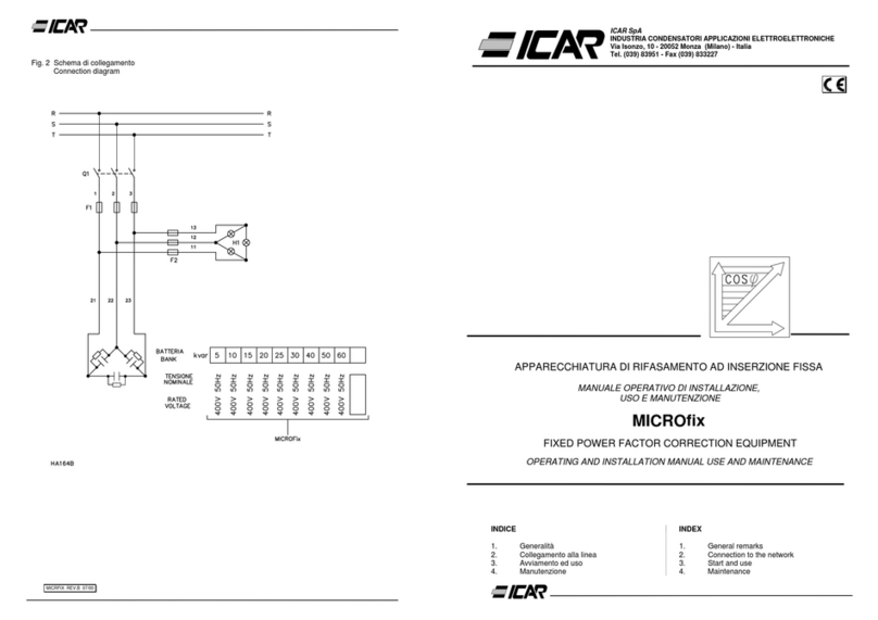
Icar MICROfix Installation and operation manual

