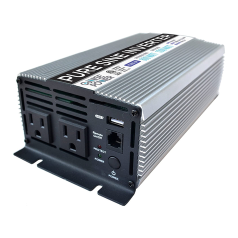
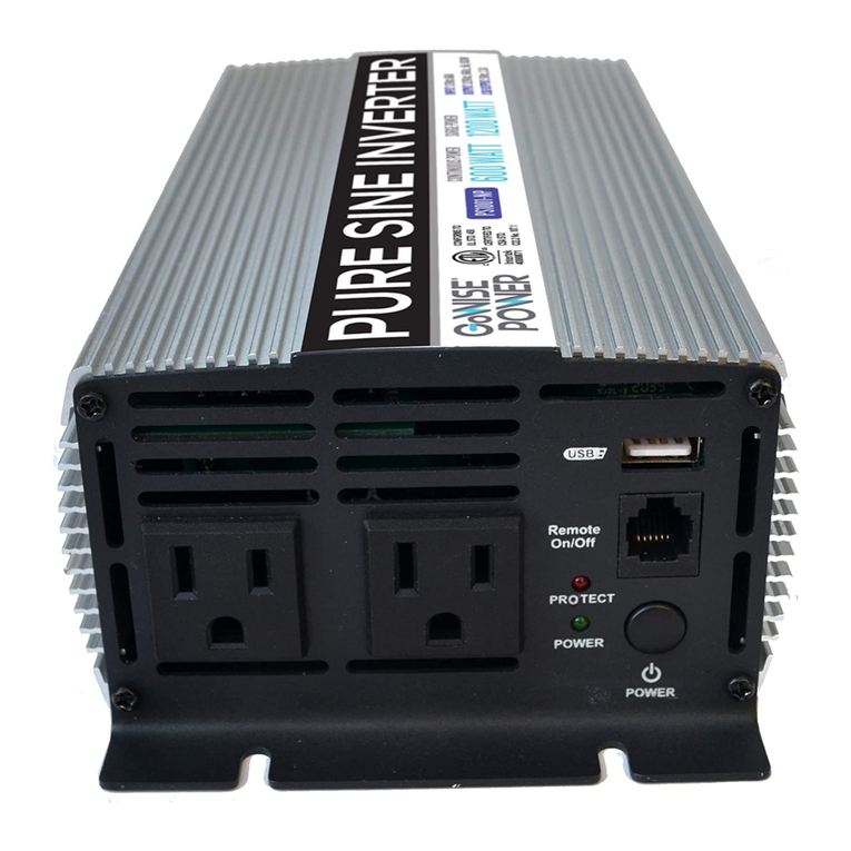
GoWISE PS1001-NP User manual

IMPORTANT SAFETY INFORMATION. SAVE THESE INSTRUCTIONS.
TO REDUCE THE RISK OF INJURY, USER MUST READ AND UNDERSTAND THIS INSTRUCTIONAL
MANUAL. THIS MANUAL CONTAINS IMPORTANT INFORMATION REGARDING THE OPERATION
AND INSTALLATION OF PRODUCT. PLEASE RETAIN FOR FUTURE REFERENCE.
PURE SINE WAVE INVERTER
USER MANUAL
WWW.GOWISEPOWER.COM
PS1001-NP
PS1003-NP
PS1005-NP
PS1002-NP
PS1004-NP
PS1006-NP

2
THANK YOU FOR YOUR PURCHASE!
UNPACKING & INSPECTION
Thoroughly inspect the products. The package
should contain the following:
1.1. Inverter
2.2. 2 Ft. + (Red) and - (Black) DC Cable
3.3. Remote
4.4. 15 Ft. Cable
5.5. User Manual
Contact Our Customer Care Team
855-233-9199
support@gowiseusa.com
Live Chat at gowisepower.com
M-F 8:30am - 4:00pm MST

Unpacking & Inspection.........................
Introduction..............................................
Standard Features........................
Protection Features.......................
Remote.........................................
Safety Instructions.................................
General Safety Instructions............
Battery Precautions.......................
DC Connection Precautions ..........
Personal Safety Precautions .........
General Overview....................................
DisplayOverview............................
Installation................................................
Preparing for Installation................
Inverter Unit Location.....................
Installation Guide...........................
Installation Materials......................
Operation..................................................
Maintenance.............................................
BatteryMaintenance......................
Inverter Maintenance.....................
Troubleshooting.......................................
Specifications...........................................
Warranty...................................................
2
4
4
5
6
7
7
8
8
8
10
11
12
12
13
14
15
16
17
17
17
18
20
22
TABLE OF CONTENTS

4
INTRODUCTION
GoWISE Power Pure Sine Wave Inverters provide the convenience of household
type power to run a wide variety of appliances, with low THD <3%. GoWISE
Power Inverters converts 12.5 VDC to 115 VAC household power.
•This unit uses the latest in soft start technology. The output voltage
gradually increases to the normal value from low value after the inverter is
turned on. It can reduce a transient large current attack and help to start
the hard start load. Large power inductive loads, such as electrical motors
or capacitive loads (large power SMPS), adopt soft start.
•LED indicators are used for power input type and service notifiction.
•During normal operation, display and gauges are blue and green.
•This innovative design takes the stress and mystery out of using an inverter
for RV’s, and specialty vehicles.
•Design includes 2x surge capability for demanding loads, convenient outlets
and a USB charging port.
STANDARD FEATURES
• Dual color gauges for AC power output and battery DC input
• 5V/ 2.4A USB power port and convenient outlets
• Compact and lightweight design
• Soft start noise filtered technology with 2x surge capability
• On/Off remote with 15 foot cable included
• Built-in safety with overload, over temperature, short circuit and reverse
polarity protection. Audible alarm and shut down for low and high DC
voltage, overload and over temperature conditions.

INTRODUCTION
GoWISE Power Pure Sine Wave Inverters are protected by a variety of features
including:
Reverse Polarity Protection
The fuses will burn out when the positive and negative cables are reverse
connected to protect the inverter.
Low Battery Shutdown
When the inverter is in low voltage, an alarm will go off first and if the voltage
continues to reduce, the LED will turn red and the inverter will shut down. If the
voltage rises to 12V +/- 0.5V, the inverter will automatically restart and the LED
will turn from blue to green.
Over Temperature Protection
The inverter will automatically protects itself when it reaches a high
temperature. An alarm will go off first then the LED will be red. The inverter will
shut down and auto-restart.
Overload Protection
The inverter will automatcially protect itself when the load is too high. An alarm
will go off first then the LED will be red. The inverter will automatically shut
down. The inverter will need to be restarted manually.
Over Voltage Protection
The inverter will automatically protect itself when it is in high voltage. The LED
will be red and the inverter will automatically shut down. When the voltage
drops to 15.5V +/- 0.5V, the inverter will auto restart.
Output Short Circuit Protection
The inverter will automatically self protect the unit by shutting down in the event
of a short circuit. It will auto restart after shutting down when the short circuit is
removed.
5

6
GoWISE Power Pure Sine Wave Inverter Remote
1.1. The Inverter Includes a remote, mounting screws, and 15 Ft. cable.
2.2. The remote is designed to be mounted on a dash or other flat surface.
3.3. The remote cable should be plugged into inverter and the remote before
being mounted.
NOTE: The remote is optional and not required for inverter operation. There
is an ON/OFF switch located on the inverter itself. When powering the
inverter ON, a normal indicator will be a green LED light. If the inverter short
circuits, the LED indicator will turn red.
INTRODUCTION

GENERAL SAFETY INSTRUCTIONS
SAFETY INSTRUCTIONS
7
IMPORTANT: READ AND SAVE THESE INSTRUCTIONS!
This user manual contains important safety instructions for the GoWISE Power
Pure Sine Wave Inverters that must be adhered to during installation, operation
and troubleshooting. Read and save this user manual for future reference.
Read these instructions carefully and become visually familiar with the
equipment before installation, operation, servicing, or maintenance. The
following precautionary messages may appear throughout this manual or
equipment to warn of potential hazards or to call attention to information that
clarifies or simplifies a procedure.
Before installing and using your new inverter, read all appropriate sections of
this guide and any cautionary markings on the inverter, batteries and on your
appliances.
CAUTION!
•DO NOT expose this unit to rain or snow.
•Use of attachments not recommended or sold by GoWISE Power will void
warranty and may result in the risk of fire, electrical shock or personal
injury.
•To reduce the risk of electrical shock, remove connection to AC power and
DC connections prior to maintenance or cleaning. Turning off controls
WILL NOT reduce this risk.
•HELP - Someone should be within the range of your voice or close enough
to come to your aid when working with a lead-acid battery.
•DO NOT operate the inverter if the carton or unit has significant damage
from being dropped or crushed, received a direct hit of force or is otherwise
damaged.
•DO NOT dismantle the inverter. Call the factory directly when service or
repair is required. Incorrect assembly may result in risk of electrical shock or
fire. No user serviceable parts.
•As a precaution - Keep children away from the inverter and its
components! The same potentially hazardous or lethal AC power that is
found in a normal household 115 AC power outlet can be found in the power
inverter.

8
SAFETY INSTRUCTIONS
To reduce risk of battery explosion, follow these instructions and those
published by battery manufacturer and manufacturer of any unit you intend to
use in vicinity of battery. Review cautionary marking on these products and on
engine.
SPARK - Be very cautious about dropping metal objects such as
screwdrivers and wrenches onto a battery. This could short-circuit the battery
and immediately cause a spark that may result in a fire or explosion.
DC CONNECTION PRECAUTIONS
Connect and disconnect DC output connections only after setting all inverter
switches to OFF and removing AC cords from electric power.
PERSONAL SAFETY PRECAUTIONS
1.1. WORKING IN VICINITY OF A LEAD-ACID BATTERY IS DANGEROUS.
BATTERIES GENERATE EXPLOSIVE GASES DURING NORMAL BATTERY
OPERATION. FOR THIS REASON, IT IS OF UTMOST IMPORTANCE THAT
EACH TIME BEFORE SERVICING THE UNIT IN THE VICINITY OF THE
BATTERY, YOU READ THIS MANUAL AND FOLLOW THE INSTRUCTIONS
E X ACT LY.
2.2. NEVER charge or invert power from a frozen battery.
3.3. If necessary to remove a battery from a vehicle or RV, always remove
grounded terminal from battery first. Make sure all accessories are off, as
not to cause an arc.
4.4. Be sure area around battery is well ventilated.
5.5. Clean battery terminals. Be careful to keep corrosion from coming in
contact with eyes.
6.6. Study all battery manufacturer’s specific precautions such as removing or
not removing cell caps while charging and recommended rates of charge.
WEAR - Complete eye protection and protective clothing. Avoid touching eyes
while working near battery(s).
NEVER - Smoke or allow a spark or flame within the vicinity of the battery work
area.
REMOVE - All personal metal items such as rings, watches, bracelets, etc.
when working near a battery. A battery can produce a short circuit current high
enough to weld a ring or any other metal causing serious burns.
BATTERY PRECAUTIONS

9
SAFETY INSTRUCTIONS
PERSONAL SAFETY PRECAUTIONS (cont.)
WARNING: Restrictions on Use - The Power Inverter shall not be used in
connection with life support systems or other medical equipment devices.
DANGER
•HIGH VOLTAGE
AVOID SERIOUS INJURY OR DEATH FROM ELECTRICAL SHOCK.
BEFORE PERFORMING ANY ELECTRICAL WORK TURN OFF AC POWER
SUPPLY.
•EXPLOSION HAZARD
AVOID SERIOUS INJURY OR DEATH.
MAKE CONNECTIONS IN AN ATMOSPHERE FREE OF EXPLOSIVE FUMES.
•LOW VOLTAGE
AVOID SERIOUS INJURY FROM ELECTRICAL BURNS AND SPARKS.
BEFORE PERFORMING ANY ELECTRICAL WORK DISCONNECT ANY DC
POWER SUPPLY FROM UNIT
CAUTION
•HOT SURFACES – TO REDUCE RISK OF BURNS DO NOT TOUCH WHILE IN
SERVICE.
•Polarity and wire color must be observed when making the installation
connection to a 12 volt battery.
Red DC input bar = + (positive) red cable battery connection only.
Black DC input bar = - (negative) black cable battery connection only.
NOTE: REVERSE POLARITY CONNECTION WILL DAMAGE UNIT AND VOID
WARRANTY.
SAVE THESE
INSTRUCTIONS

10
PS1002-NP
PS1005-NP
PS1 003-NP
PS1 004-NP
PS1 006-NP
PS1001-NP
USB
POWER INPUT TERMINAL
(BLACK ) = NEGATIVE
POWER INPUT TERMINAL
(BLACK ) = NEGATIVE
POWER INPUT TERMINAL
(BLACK ) = NEGATIVE
POWER INPUT TERMINAL
(BLACK ) = NEGATIVE
POWER INPUT TERMINAL
(BLACK ) = NEGATIVE
REMOTE
ON/OFF SWITCH
USB
USB
USB
REMOTE
REMOTE
REMOTE
ON/OFF SWITCH
ON/OFF SWITCH
ON/OFF SWITCH
USB
REMOTE
ON/OFF SWITCH
USB
REMOTE
ON/OFF SWITCH
GROUND LUG
TERMINAL
GROUND LUG
TERMINAL
GROUND LUG
TERMINAL
GROUND LUG
TERMINAL
GROUND LUG
TERMINAL
POWER INPUT TERMINAL
(BLACK ) = NEGATIVE
GROUND LUG
TERMINAL
COOLING FAN
COOLING FAN
COOLING FAN
COOLING FAN
COOLING FAN
COOLING FAN
POWER INPUT TERMINAL
(RED) = POSITIVE
POWER INPUT
TERMINAL (RED)
= POSITIVE
POWER INPUT
TERMINAL (RED)
= POSITIVE
POWER INPUT
TERMINAL (RED)
= POSITIVE
POWER INPUT
TERMINAL (RED)
= POSITIVE
POWER INPUT
TERMINAL (RED)
= POSITIVE
AC OUTLETS
AC OUTLETS
AC OUTLETS
AC OUTLETS
AC OUTLETS
AC OUTLETS
GENERAL OVERVIEW

11
GENERAL OVERVIEW
System Status Fault Modes
All faults conditions are accompanied by a 2-second alarm (On/Off tone).
DISPLAY OVERVIEW
No. Description Details
1 Power Button Turns on/off the inverter
2 Power Indicator Green LED for 12.5V DC Input
3 Protect Indicator Illuminates red when the Off inverter is in fault condition
3
21

12
INSTALLATION
PREPARING FOR INSTALLATION
WARNING
•This device is not ignition protected, risk of fire or explosion.
•This equipment contains components that could produce arcs or sparks.
To reduce the risk of fire or explosion, DO NOT install this equipment in
compartments containing batteries, flammable materials or fumes, or in a
location containing gasoline-powered machinery, or joints, fittings, or other
connections between components of the fuel system.
•DO NOT mount the inverter above or below your batteries.
•Electrical Shock and Fire Hazard
We recommends all wiring be done by qualified personnel. Disconnect
all AC and DC power sources to prevent accidental shock. Disable and
secure all AC and DC disconnect devices and automatic generator starting
devices. It is the installer’s responsibility to ensure compliance with all the
applicable installation codes and regulations
•Installation Precaution
The power inverter should be mounted on a flat horizontal surface or a
vertical surface. In no case should the front or rear end caps be facing in an
upward or downward position. This allows proper ventilation and product
safety of the unit as intended by design.
•Fire Hazard
DO NOT cover or obstruct the ventilation openings. DO NOT install this
equipment in a compartment with limited airflow. Overheating may result.
•Risk of fire or explosion.
•Low voltage - electrical burn and spark hazard.
•Disconnect battery power before servicing.
NOTE: This unit requires a large amperage draw from a DC battery when
in inverter mode. Care must be taken during installation to provide properly
sized cables from the battery to the inverter. Cable runs must be as short
as possible and of the appropriate size and type. See the Installation
section for more details.
Installation Recommendations and Requirements Include the Following:
The U.S. National Electrical Code (NEC)
RV Industry Association (RVIA)
The Canadian Electrical Code (CEC)
Canadian Standards Association (CSA)

8” 3”
1”
1”
INSTALLATION
13
INVERTER UNIT LOCATION
NOTE: Please re-read the PERSONAL SAFETY PRECAUTIONS section of this
manual (pg. 8-9) prior to installation. This unit must be located in a cool, dry,
well ventilated area, free from unsecured hardware. Temperature is also a
serious consideration. DO NOT mount this unit in an engine compartment or
areas where temperatures will exceed 104°F (40°C).
In addition, the following should be considered when choosing a location:
1.1. Locate inverter unit away from battery in a separate, well ventilated
compartment.
2.2. Placement of the remote status panel - A length of communications cable
is provided for remote-location of the status/on/off panel. Ensure the cable
is long enough to reach the desired location (generally in proximity to the
main panel board) and avoid any area where it can be damaged.
3.3. Ventilation - Allow at least 8 inches (20cm) of space at the DC end of the
inverter for air flow, 1 inch (2.5cm) on each side, and 3 inches (7.5cm) at the
AC end of the inverter. For cooling, the size of the space is not as important
as the overall supply of air. The more clearance for ventilation around the
unit, the better the performance. DO NOT allow the ventilation openings on
the ends of the unit to become obstructed.
4.4. Cable Routing - Large DC cables and over current protection (fuses/
circuit breakers) will be located in proximity to this unit. Choose a location
AS CLOSE AS POSSIBLE to the DC battery bank serving the unit. This will
provide optimum performance for the unit and keep cable sizes smaller.
Location of the AC power is less critical than the DC supply.
MOUNTING - The weight of the inverter is very heavy. Be sure to place the
inverter on a stable surface such as the floor, a table, or stand. Make sure
the areas you place the inverter on can withstand the weight of the inverter.
In addition, be sure to affix the product with the provided screws to keep the
inverter from falling or moving.

14
INSTALLATION
INSTALLATION GUIDE
STOP: BEFORE INSTALLING YOUR INVERTER, READ AND FOLLOW THE
CHECKLIST BELOW:
•Begin with the power switch and main shore/station power breaker in the
OFF position. Ensure that all over current protection (e.g. fuses and/or
circuit breakers) are ready for use, not blown or tripped.
•Use great care to ensure the polarity of the DC connections are correct or
damage will result to your inverter.
•Verify all connections are tight, corrosion free and of good integrity.
DO NOT OPERATE THIS UNIT WITHOUT THE EARTH CONNECTION
ATTACHED.
The earth conductor is permitted to be 1 common size smaller than the DC
positive (+) conductor (Example: DC += 2 AWG, Earth = 4 AWG).
12 Volt DC Battery Source - Batteries can be a single battery or multiple
batteries in parallel. Batteries connected in parallel boost amp hours while
maintaining voltage. Tapping each battery as shown balances the load of the
battery.
Parallel batteries illustrated:
DO NOT connect the following in parallel:
•Batteries made by different manufacturers
•Different types of batteries
•Batteries that have different Ah ratings
Decreased battery life and improper charging will result.
CAUTION!
Parallel Batteries (12V) for a 12V Bank
(Increases the Amp/Hr Capacity)

15
1. DC Cables - The DC portion of the power Inverter requires a large amount
of amperage in Inverter mode. Cable size and length is of extreme
importance and should be well thought out and planned per this manual
before beginning installation. Items to consider are as follows:
a. Cable Size - Size is based on amperage draw of the unit compared to the
maximum amperage a cable can carry. We recommend NO MORE THAN
a 10% drop in voltage from source (battery) to the GoWISE Power unit or a
cable run not longer than 6 feet.
Recommended cable sizes:
Wattage Cable Size Cable Length ANL
Fuse
600W 6# pure copper 6 ft. 150A
1000W 4# pure copper 6 ft. 150A
1500W 2# pure copper 6 ft. 250A
2000W 0# pure copper 6 ft. 300A
3000W 2/0# pure copper 6 ft. 500A
b. Installing DC Safety ANL Fuse: Install fuse in positive (+) cable within 7” of
battery. See above table for recommended fuse.
DO NOT ATTEMPT CABLE TERMINATION BY MEANS OTHER THAN
PROPER CRIMPING, WITH A PROPERLY CALIBRATED TOOL. SOLDER AND
AUTOMOTIVE REPAIR TYPE BATTERY TERMINALS ARE NOT ACCEPTABLE.
USE OF ANY OF THESE TYPES OF TERMINATIONS WILL RESULT IN
PREMATURE, UNWARRANTIED FAILURE OF THE GOWISE POWER UNIT.
2. AC Cables – AC Cables should be readily available in both 2 and 3
conductor. Size is based on the maximum amperage to be passed through
the cable and unlike DC does not take into account the length of the cable
run and voltage drop.
INSTALLATION
INSTALLATION MATERIALS – CABLING
Use great care to ensure the polarity of the DC connections are correct
or damage will result to your inverter.

16
OPERATION
Inverter Power On and Off
The AC output can be turned on or off by pressing the POWER button on the
display panel. With the remote feature, the inverter can be turned on or off
remotely as well.
Operating the Inverter within the Load Range
Load Type Precautions
•Resistive Loads – Be careful with resistive loads that generate heat
(toasters, electric stoves, etc.). Due to the high current drawn by these
loads, a typical battery bank would be drained very quickly. Therefore,
it would impractical to run the inverter with these types of loads for an
extended period of time.
•Motor Loads – Use caution with the type of motor that you connect the
inverter. Induction motors require a much higher startup current than their
running current. Since motors vary in their characteristics, it is best to test
the motor load on the inverter. If the motor does not start or loses power,
the inverter should be turned off and the motor removed. If the motor
startup current is too high, the inverter will turn itself off.
NOTE: Operation of this equipment in a residential area is likely to cause
harmful interference in which case the user will be required to correct
the interference at their own expense. If in a residential setting you are
encountering interference with TV and Radio reception while NOT in inverter
mode, then simply disconnect AC power from the power Inverter to confirm
if this unit is causing the interference, if so explore the following options to
minimize interference:
1.1. Make sure your AC connections include a proper ground connection
2.2. Reposition your receiving antenna
3.3. Purchase a separate AC line filter
4.4. Relocate the affected appliance so it is further separated from the power
inverter
CAUTION: Check the power consumption of the unit to make sure that
appliance is within the power range of the inverter to ensure that you DO NOT
overload the inverter. Overloading the inverter will void the warranty.
This equipment has been designed to comply with:
•FCC Class A
•Underwriters Laboratories: Standard 458 Power Converter/Inverter
Systems for Land Vehicles and Marine Crafts

17
MAINTENANCE
BATTERY MAINTENANCE
INVERTER MAINTENANCE
Periodically, check the batteries to make sure they are good condition. Check
the terminals for corrosion and clean them with a wire brush if necessary. If
the batteries are flooded lead-acid, check the electrolyte levels every month
and top off with distilled water if needed. Finally, check the battery voltage in
accordance with the manufacturer’s specifications.
Little maintenance is needed to keep the power inverter running properly. To
keep the unit running optimally, you should:
•Wipe the unit’s exterior with a damp cloth to clean off dust buildup.
•Check that the DC cables are securely connected and the fasteners are tight.
•Clear the ventilation holes of dust buildup.

18
TROUBLESHOOTING
WARNING
ELECTRICAL SHOCK HAZARD
DO NOT disassemble the inverter. It does not contain any serviceable parts and
attempting to service the unit could result in an electrical shock or burn.
Failure to follow these instructions can result in death or serious injury.
How to Troubleshoot Common Fault Conditions
This section details how to troubleshoot the power inverter. Follow the process
below to narrow down the cause of unit fault conditions. Go through this
process before contacting Customer Care Team.
1.1. Check for any fault indicators. If a fault indicator is displayed, note it down
before proceeding further.
2.2. Note the conditions around the time the fault condition occurred. Record
the following details:
•Battery voltage at the time of failure
•How many watts the inverter was putting out
•Extreme environmental factors (ambient temperature, vibrations,
moisture, etc.)
3.3. If no fault indicators are displayed, check the installation:
•Is inverter properly mounted and located in a clean, dry, adequately
ventilated environment?
•Is the battery in good condition?
•Are the DC and AC cables properly sized, in good condition, and have
clean and tight connections?
•Have any fuses blown?
4.4. When steps 1 through 3 have been completed, contact Customer Care
Team for further troubleshooting. Be prepared to provide information
surrounding the unit failure as well the unit model and serial number (the
serial number is normally underneath the product).

19
TROUBLESHOOTING
If the GoWISE Power Pure Sine Wave Inverter still malfunctions after all
solutions have been exhausted, please contact our Customer Care Team at
855-233-9199.
Fault Message Condition Action
LOW DC ALARM
Battery voltage has
fallen below 10.5 V
+/- 0.5 V
•Check battery voltage and recharge if needed
•Check for proper DC cable sizing
•Check for loose connections and tighten if
needed
•Charge batteries to clear fault
LOW DC SHUTOFF
Battery voltage has
fallen below 10.0 V
+/- 0.5 V and inverter
output is shutoff
•Check battery voltage and recharge if needed
•Check for proper DC cable sizing
•Check for loose connections and tighten if
needed
•Charge batteries to clear fault
HI DC SHUTOFF
Battery voltage is
above 15-16.5 V and
inverter output is
shutoff
•Check for other DC inputs, such as an over
voltage alternator, and disconnect if needed
•Decrease input voltage to clear fault
HI TEMP SHUTOFF
Inverter internal
temperature is above
> 149°F (65°C) and
inverter output is
shutoff
•Reduce the loads connected to the unit AC
output.
•Check for proper ventilation to the unit and
remove any obstructions
•Check the ambient temperature and move
the unit to a cooler location if possible
•Push button twice to clear fault
OVERLOAD
SHUTOFF
Inverter output is
greater than 105%
and is shutoff
•Reduce the loads connected unit AC output
•Check for loads that have a high surge &
remove if needed
•Push button twice to clear fault

20
SPECIFICATIONS
Description Pure Sine
Wave Inverter 600W 1000W 1500W 2000W 3000W
Input
Characteristics
Input Over-Voltage
Protection 15~16.5VDC
Input Under-
Voltage Protection 9.5~10.5VDC
Voltage Range 11~15VDC
No Load Current ≤1A @12.5VDC
Output
Characteristics
Continuous Output
Power 600W 1000W 1500W 2000W 3000W
Surge Power 1200W 2000W 3000W 4000W 6000W
Effiency MAX. ≥90%
Output Waveform Pure Sine Wave (THD<3% @Normal Load)
Output AC Voltage AC 105-125V
Output Frequency
Level 60 ± 1HZ
Protection
Input Protection Over/Under Voltage, Reverse Polarity (Internal Fuse)
AC Output
Protection Short-Circuit, Overload
Others Over Temperature Protection
This manual suits for next models
5
Table of contents
Other GoWISE Inverter manuals
Popular Inverter manuals by other brands

MDV
MDV HM/II-65S Service manual

Mitsubishi Electric
Mitsubishi Electric FR-A760 Series instruction manual

Offroad Living
Offroad Living AllSpark PS Series user manual

Northern Lights
Northern Lights Lugger OM843NW2 Operator's manual

Mase
Mase IS 2.6 Use, maintenance and installation manual

Haier
Haier 1U35MECFRA-3 Service manual