Offroad Living AllSpark PS Series User manual

AllSpark® Inverters
USER MANUAL
PS Series: Pure Sine Wave
PI Series: Modified Sine Wave
(Next review date 15.12.19)
WELCOME

Please read this manual thoroughly before installing and operating your AllSpark
®
Inverter. This manual contains important
information and safety instructions required to obtain the performance, reliability and safe operation for your application. Please keep
this manual for future reference. AllSpark® Inverters have been designed in a compact size, containing an innovative advanced
microprocessor controller, with high electrical efficiency & cooling fans resulting in a unit you can rely on every time.
AllSpark
®
is a registered Trade Mark in Australia which has been proudly designed & developed by the team at Offroad Living. Use
of this Brand name or Trade Mark without the express permission of Offroad Living is expressly prohibited. Offroad Living is Owned
and Operated by a True Blue Aussie family based in Perth Western Australia.
WARNINGS, CAUTIONS AND NOTES
It is very important that any operator or installer of this AllSpark
®
Inverter, read and follow all WARNINGS, CAUTIONS AND NOTES
and all installation and operation instructions.
WARNINGS: INVERTER OUTPUT
This heavy-duty device produces voltages similar to commercial AC power
Danger of shock or electrocution. Treat the Inverter output the same as commercial AC power
Do not use the Inverter near flammable materials or in any locations that may accumulate flammable gases
This electrical device will briefly spark when electrical connections are made or broken. This is normal to charge the internal
capacitors
Do not allow water or other liquids to contact the Inverter or operate in extreme humidity
Do not use appliances with damaged or wet cords
CAUTIONS: INVERTER OPERATING ENVIRONMENT
Surrounding air temperature should be between 0°C and 45°C. Ideally between 15°C and 25°C. Keep the Inverter away
from direct sunlight if possible to reduce operating temperatures
Keep the area surrounding the Inverter clear to ensure free air circulation around the unit. Do not place items on or over the
Inverter during operation
The unit will automatically shut down if the internal temperature gets too high. Restart the Inverter after it cools
This Inverter series is designed to be powered from for DC power voltages: 12V only for all models expect the 24v PS-500024
model. Please very carefully check the DC voltage of your Inverter and only connect it to the correct DC voltage power source.
Failure to do so will destroy the unit. Verify the DC voltage with your retail seller if it is not clearly marked on the product or its
package. These units do not have AC mains automatic transfer compatibility built in. To achieve this you must install an AC
circuit breaker and Residual current device (RCD) along with an AC transfer device. Any AC mains cabling, connections or
terminations should be undertaken by a licensed Electrician in accordance with local wiring standards
Do not reverse the DC input polarity or connect to the incorrect DC voltage. This will damage the Inverter and it will void the
warranty
WARNING: DANGER OF BATTERY EXPLOSION – YOU MUST INSTALL A FUSE
Loose connections or undersized cables can result in a severe decrease in voltage and it can cause damage to cables and
insulation
Failure to make the correct polarity (Positive & Negative) connections between the Inverter and the battery bank can result in
blowing fuses in the Inverter and can permanently damage the Inverter. Damage caused by reversed polarity is not covered
under the warranty
Making the initial connection to the DC Positive (Red +) terminal may cause a spark as a result of current flowing to charge the
capacitors within the Inverter. This is a normal occurrence
Because of the possibility of sparking however, it is extremely important that both the Inverter and the battery/s be positioned
far from any possible source of flammable gases. Failure to heed this warning could result in fire, explosion, serious personal
injury or death
Operating the Inverter without correctly grounding the unit may result in an electrical shock

GETTING STARTED WITH YOUR ALLSPARK
®
INVERTER
When a motorized appliance or a tool turns on, there is almost always an initial surge of power to start up. This surge
of power is referred to as the "starting load" or "peak load". Once started, the tool or appliance requires less power to
operate. This is referred to as the "Continuous Load". This information is usually stamped or printed on most
appliances and equipment or can calculated as per below:
Multiply: AC AMPS X 230 (AC voltage) = WATTS
To determine the current draw from your batteries, you take the WATTS that you device draws /12 volts to give you the
DC amps.
This formula yields a close approximation of the continuous load of your appliance.
Multiply: WATTS X 2 = Approximate starting load for most appliances
This formula yields a close approximation of the starting load of most appliances. Exceptions are motorized appliances
such as pumps, freezers and air conditioners. These appliances can have peak startup loads of up to 8 times the rated
continuous load.
FRONT PANEL AND REAR PANEL REPRESENTATION
(some models will have 1 or 2 x 230v outlets or multiple LCD screens and arrangement may change with model updates over time)
(300W-1500W)
(2000W-6000W)
4000/8000w 24v model includes AC line terminals for hard wired connections by licensed electricians
All Pure Sine Wave Models include a 5m remote power control panel with status indicator for remote switching

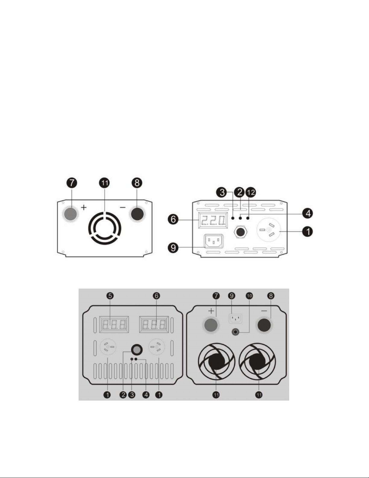
COMPONANT DESCRIPTIONS
The follow items describe the components shown on the images on each size of Inverter shown on the previous
page. These images are provided for information purposes only. Models may change slightly as a result of
product developments and improvements over time.
1. AC outlets – All models have 2 x 230v outlet sockets), for 4000VA and above capacity, output cable terminals are
also provided in addition to 2 x output sockets
2. ON/OFF Switch. Turns the Inverter circuits ON and OFF. Pure Sine wave models are now supplied with a 5m
remote switching cable and control panel with power status indicator. You can only switch it from one source or the
other, not both active at the same time.
3. Fault indicator - if this LED is lit in red, the unit encountered a fault
4. Power indicator - if LED is lit green, AC power is present (only for PS-C and EPS series), if it is lit in blue the device
has entered Inverter mode
5. Battery voltage digital display
6. Output voltage digital display. For 300-1500VA models, this display not only displays the output voltage, it also
indicates the battery DC voltage at the startup of the Inverter and when the battery voltage drops too low, to protect
the battery voltage for a short period of time
7. DC positive ( red + ) input terminal, connect it to the battery Positive ( red + ) terminal
8. DC negative ( black - ) input terminal, connect it to the battery Negative ( black - ) terminal
9. AC power cord, connect to AC mains power (Note: Only available on PS-C and EPS items which include charger
and or auto transferring function)
10. Input over current circuit breaker. Automatic trip off if the device is over current. Press it in to reset after trip (if
applicable to your model)
11. High speed brushless motor cooling fans. The cooling fan automatically turns on to cool the Inverter when the
temperature inside the Inverter exceeds the preset limit. It turns off when the temperature reduces
12. Charger indicator. If LED is lit green, AC power is present and it indicates that the Inverter is charging the battery
(only on applicable charger models)
SIZING THE BATTERY
The following is a basic guide to help determine the minimum battery bank Ampere-hour (Ah) rating that you will
need to operate appliances from the Inverter and run any DC appliances powered by the battery bank. This
determine capacity for ongoing operation. The current producing ability of the battery should be check with the
battery manufacturer to ensure it can produce the current required for your calculated demand. Follow this
algorithm to calculate an approximate battery capacity you need:
Example: Calculate the battery size needed to run 100W for 7.2 hours with a 12V battery:
Battery Ah = Run time (hours) x Load Power / (battery voltage x 80% x 90%)
Battery Ah = 7.2 x 100W / (12V x 80% x 90%) = 83Ah
Note:
The type of batteries you use to power your high-power Inverter is important. Batteries used to start engines are not
designed to be repeatedly deeply charged and discharged. We recommend using “deep-cycle” batteries with a sufficient
continuous output current to matches the maximum output current of the inverter. Small amp hour batteries will struggle
to provide enough current or overcome the voltage sag when connected to larger inverters (over 1000w) and may
encounter low voltage protection modes as a result. If you experience this, try using a larger battery or two batteries
connected in parallel. When connecting the Inverter to a battery/bank use the thickest stranded insulated copper wire
available in the shortest length practical that at least meets the maximum current draw of your inverter + 20%. Ideally
only use the enclosed battery cable or consult your seller if a longer cable is required.

INSTALLING AND CONNECT THE INVERTER
Your Inverter should not be mounted under the hood of a vehicle or external to the vehicle. It is not waterproof. This
Inverter has two DC cable connections, one Positive and one Negative. The order of steps in the following procedure
minimizes the danger of sparking near the battery bank.
(
PS or PI Series without charger)
(PS-C & EPS Series with charger)
1. Before mounting and connecting the Inverter, the ON/OFF switch must be in the OFF position
2. The Inverter should be mounted horizontally using corrosion-resistant fasteners sized 10g or larger
3. Prepare all cable set ends with ring terminals/battery lugs at the battery ends
4. Install one fuse holder (with appropriately an appropriately sized fuse) or manual reset circuit breaker on the positive
cable as close as possible to the battery bank end to protect the cable from excess current draw
5. Make sure the ON/OFF switch located on the front panel of the Inverter is in the OFF (“O”) position
6. Ensure all appliance cords or extension cords are disconnected from the Inverter
7. Connect the unfused cable to the negative ( black - ) terminal of the battery bank
8. Connect the negative ( black - ) cable to the Inverter’s negative ( black - ) terminal
9. Insulate the end of cable to be connected to the positive ( red + ) Inverter terminal
10. Connect the fused cable to the battery bank positive ( red + ) terminal
11. Connect the positive cable end to the positive ( red + ) Inverter terminal
12. For PS-C and EPS series, connect the detachable power cord to the AC mains socket
NOTE: Sparking is normal for the first connection
Sizing the circuit protection
Your Inverter must be connected with cables that can handle the maximum continuous current draw of the Inverter.
Cables are supplied with the unit. If using these cables, they can be used in that short length as is, but it is highly
recommended to install circuit protection. Circuit protection protects the cable from overload or damage from a short
circuit or dead short. It is not designed to protect the Inverter. This protection is already built into the Inverter.
To calculate the circuit protection, take the continuous wattage of the Inverter you have purchased, divide it by 12 volts
to get the maximum amp draw add a minimum of 10 amps (ideally 10% or more). The cable must be able to carry at
least the amount of the chosen circuit protection + 20%.

OPERATION
1. Check the battery voltage to make sure it matches the DC input voltage of the Inverter. Only connect a 12V DC
input Inverter to a 12V DC battery or 24V DC input inverter to 24V DC battery.
2. Turn On (“I”) the Inverter. Make certain the overload audible alarm doesn’t sound
3. Turn OFF (“0”) the Inverter. The audible alarm may also sound a short "chirp". This is normal
4. When you have confirmed that the appliance to be operated is turned off, plug an appliance cord into one of the
230V AC outlets on the front panel of the Inverter or into general purpose outlets (GPO’s) connected via the hard
wired line terminals (on 24v models only)
5. When you first turn ON the Inverter, the Inverter starts a self-detection procedure. The audible alarm will sound a
beep at the same time and the power indicator will be lit in green. If the fault indicator is lit in red, then turn the
Inverter off. This Inverter has a soft starting function. Always wait to turn ON your appliances for a minimum of 3
seconds after powering up the inverter
6. Turn the appliance ON
Notes:
The audible alarm may make a momentary "chirp" when the Inverter is turned OFF. This same alarm may also
sound when the Inverter is being connected to or disconnected from the 12V DC battery bank. When using an
extension cord from the Inverter to an appliance the extension cord should not be longer than 15m and ideally should
be of good quality and cable thickness to ensure no voltage drop along the cord.
BATTERY BACK UP TIME
You may take this simple algorithm to calculate the use time of your battery pack with the Inverter:
Back up time (t) = (Battery voltage X Battery Amperage X 80% X 90%) / Load power.
Example: To calculate the backup time of a 12V/100Ah battery with a 100Watts load,
Backup time (t) = 12 x 100 x 80% x 90% / 100W = 8.6hrs
Note: This back up time calculation algorithm is for your reference only. Actual back up is subject to many other factors
as mentioned in SIZING THE BATTERY.

SPECIFICATIONS
(800W – 1200W)
Model AS-80012IMSW AS-100012IPSW AS-120012IMSW
Continuous power 800W 1000W 1200W
Maximum power 1000W 1200W 1500W
Surge power 1600W 2000W 2400W
Output Sine wave Modified Pure Modified
DC cutout (V) 10.5 Volts (Low) & 15 Volts (High)
No Load Draw 0.2 Amps
AC Output 240V (+/- 8% in accordance with Australian voltage standards)
AC Sockets Dual 240 Volt 10 Amp Australian standard 3 pin
AC hard wire
terminals No
Remote switch panel
No Yes – 5m cable No
Display
1 digital voltage meter shows the output voltage and battery voltage. The battery DC voltage only shows
at
the startup of the Inverter and when the battery voltage drops to low battery voltage protection level. Three
LED indicators shows power, fault & protection
Efficiency ≥90%
THD THD≤3%
Output frequency 50 Hz±1 Hz
Isolation strength
≧
1500Vac/1min, Between input and output and the casing
Insulation method Optical Coupling DC-DC-AC
Protection Short circuit protection, over load
protection, over temperature protection, battery low voltage protection,
battery over voltage protection, battery low voltage warning
Minimum Cable size
for DC connection 6B&S 4B&S 3B&S
Dimensions 225x150x90mm 245x150x90mm 275X150X90mm

(2000W - 6000W)
*Specifications are subject to change without prior notice.
TROUBLESHOOTING
PROBLEM: The Inverter will not power ON, power indicator (blue) is not lit
Reason Solution
Poor contact with battery terminals Shut down Inverter and disconnect. Clean terminals thoroughly and reconnect
Blown DC battery fuse(s) Turn off Inverter. Replace fuse(s) with same type and rating
24v models require remote control to power on Connect unit to battery, then power up unit with power button on front then turn
on with remote control
PROBLEM: The appliances do not work, the fault indicator (red) is lit, Audible alarm ON
Reason Solution
Battery voltage below 10 Volts* (*20v for 24v models)
Charge or replace battery
Inverter is too hot (unit is in thermal shut down mode) Allow Inverter to cool. Check for adequate ventilation. Reduce the load on the
Inverter to rated continuous power
The Inverter is overloaded Reduce the load
Unit may be defective. See Warranty and contact AllSpark® customer service
Model PI-300012 PS-250012 PS-500024
Continuous power 2400W 2000W 4000W
Maximum power 3000W 2500W 5000W
Surge power 4800W 4000W 8000W
Output Wave Modified Pure Pure
DC input(V) 12 Volt 24 Volt
DC cutout (V) 10.5 Volts (Low) & 15 Volts (High) 21.0 Volts (Low) & 30 Volts (High)
No Load Draw 0.3 Amps 0.6 Amps
AC Output 240 Volts (+/- 8% in accordance with Australian Voltage standards
AC Sockets Dual 240 Volt 10 Amp Australian standard 3 pin sockets
AC hard wire terminals No Yes up to 4mm2 cable input
Remote switch panel No Yes – 5m cable Yes – 5m cable
Display Single
digital voltage meter and LED
indicators Dual digital voltage meters and LED indicators
Efficiency ≥90%
THD THD≤3%
Output frequency 50 Hz±1 Hz
Isolation strength
≧
1500Vac/1min, Between input and output and the casing
Insulation method Optical Coupling DC-DC-AC
Protection Short circuit protection, Over load protection, Over temperature protection, Battery low voltage protection,
Battery over voltage protection, Battery low voltage warning
Minimum Cable size for
DC connection 0 B&S 1B&S 3/0 B&S
Dimensions (LxWxH) 310x150x90 430x180x110 490x180x140

FAULT CODES
PS PURE SINE WAVE INVERTER ERROR CODE AND TROUBLE SHOOTING
ERROR CODE PROTECTION MEANING
OH Over Temperature Protection. Reduce load or stop the inverter and restart it after it cooling down
OL Current Overload. Reduce the load current and reset.
L Battery under voltage protection. Recharge battery or use larger capacity batteries
H Battery over voltage protection. Battery voltage is too high (over 15v) or in Equalization charge cycle
from battery charger. Wait for charging to end or reduce voltage below 15v for 12v applications
EO Abnormal output voltage
HH Protection against heavy load starting, switch on the inverter before switch on any load.
HE Protection against high percentage overload, or short circuit.
THE LEGAL STUFF
The following information is applicable for any purchase directly from Offroad Living and not from 3rd sellers.
A copy of our Warranty Policy, Terms & Conditions of Sale and Privacy Policy can be found on our website at www.offroadliving.com.au
These documents outline your rights and obligations under this Warranty and Australian Consumer Law with regards to Consumer Guarantees.
If you have any queries about Warranty please contact us at warranty@offroadliving.com.au
If you have a need for repairs after the Warranty period please email us at repairs@offroadliving.com.au
Outside of that if you have any technical queries about this product you can email us at support@offroadliving.com.au
If purchased through an authorize 3rd party or reseller, please refer any initial enquires to the original place of purchase for technical
support or warranty enquiries.
TO THE NEW TRIBE MEMBER
From the Tribe at Offroad Living, we sincerely thank you for your purchase. We hope this Inverter helps to increase your enjoyment of the
great outdoors and gets you “Offroad” more often. If at any time you need further advice on 4wd, camping or caravan products please don’t
be a stranger and feel free to hit us up on Facebook
https://www.facebook.com/groups/offroadliving/
This manual suits for next models
7
Table of contents