Grace Industries In-Command Accountability System Operation manual

Patent Protected
US 7,538,666
In-Command®
Accountability System
User’s Information
Grace Industries, Inc.
In-Command®3.05.0100

2
Protecting Personnel
With advanced hardware and software features,
In-Command®systems provide an unbeatable
method of protecting your firefighters and personnel
at any scene while simplifying the Accountability
responsibilities of the Incident Commander.
04-2020

3
Important!
*IMPORTANT* NFPA-1982, 2018 edition, RF PASS Requirements:
The NFPA-1982, 2018 edition, includes minimum requirements for RF PASS systems. The
use of the In-Command®software under its default installed-configuration is compliant with
NFPA requirements for RF PASS systems.
The host PC running the In-Command®software must have its speakers enabled
and volume turned up to a level that can be heard in loud fire ground environments.
The default installation of the In-Command®PC software uses audio files to activate or
‘play’ on the host PC’s speakers for various functions including ‘RF PASS alarm’, ‘RF
PASS Evacuation alarm initiated’ and ‘loss-of-signal alarm’. The In-Command®PC
software allows custom audio files to be used in place of the default audio files, however
any change to these audio files may jeopardize NFPA compliance if they are not of a
suitable nature. Caution should be used if the default audio files are changed.

4
Getting Started
Table of Contents
Introduction 5
Minimum Computer Requirements 10
Installing USB Drivers from FTDI 11
Connecting the MX900-H 12
Installing System Software 13
Operation Setup 14
Setting the System ID 23
System Settings 27
Configure Connections –
Set the Receiver Type 30
User Setup 31
Create a Name File 32
Prepared to Monitor Users 46
Configuring Incident Settings 47
Location Setup 54
GPS Device Mapping 58
Setting Audio Alarms 81
Configuring Notifications 84
Save and Exit Configuration 93
Start an Incident 95
Monitoring Screen 96
User Status Images 110
Performing Actions on Users 127
Viewing System Information 151
Saving the Incident 168
Cancelling the Incident 168
Using the Incident Viewer 169

5
Introduction
MX900-H
Transceiver
Thank you for purchasing a Grace Industries Accountability System
In-Command®Accountability System uses In-Command®Software and the components listed
below to provide complete accountability for your firefighters during an incident.
System Components
MX900-H Transceiver
SuperCELL®SC500-H, TPASS®5 or other Grace telemetry devices assigned to personnel
for monitoring
Micro Repeaters and External Antennas may be added as needed to
enhance system effectiveness
Return to TOC

6
Safety Monitoring of Personnel
Each Firefighter equipped with a SuperCELL or
TPASS telemetry device is monitored for PASS
Status such as ON, OFF or ALARM.
*PASS stands for Personal Alert Safety System
Each worn device can be sent an Evacuation, PAR, or
Roll Call Signal with a simple button press
All Firefighters on scene are automatically populated
in the In-Command software and are sorted in real-
time based on priority, with Alarm being the highest
priority
When an Alarm, Evacuation, PAR, or Roll Call signal
is present, the SuperCELL or TPASS user's device
will go into a loud audio alarm indicating to the
wearer that action is required
Return to TOC

7
MX900-H Transceiver
Receives and processes radio signals from
SuperCELL and TPASS devices and
transmits Evacuation, PAR, and Roll Call
signals to these firefighter worn devices
Monitors PC communications through the
USB port and goes into Alarm if the
communications fail at any time
External Antennas may also be used as
needed
Return to TOC

8
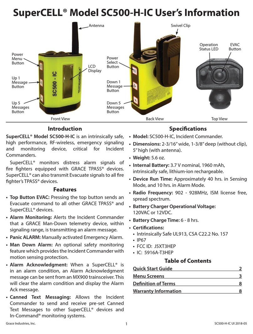
SuperCELL SC500-H
Personnel Monitoring for Incident Commander
2-Way Emergency Signaling
Excellent for Officers when not monitoring In-Command Computer
Small, Rechargeable, Lithium-ion Battery Powered Transceiver
Back Lit LCD Display Enhances Readability
Receives ALARM signals, Displays and Identifies other TPASS devices in ALARM
Repeats Alarm and Evacuation Signals
Receives Evacuate, PAR, and Roll Call Signals from In-Command
Audible Alarm Signal and Vibration indicate function
Ability to send and receive preloaded canned messages
Manually turn ON and OFF by pressing side buttons simultaneously
Lack-of-Motion Alarm Function
Select time to Alarm (30, 60, 90, & 120 seconds)
Single Button “Alarm” function
Side Buttons for Easy Reset and Mode Selection
LCD Display allows monitoring of other TPASS in Emergency Alarm
Complete Name Database for all users
Sturdy construction for long life
Return to TOC

9
TPASS-5
2-Way Emergency Signaling
and Automated Accountability
NFPA Compliant Two-way signaling TPASS transmits status
of firefighters to In-Command
Receives: Evacuation, PAR and Roll Call Signals
Smart-Signal®technology repeating function
Single button ALARM activation or automatic Lack-of-Motion
ALARM
Three axis, solid state motion sensor
Two Methods of Attachment
Over 40 hours in sensing mode
Over 95dBA at 10 feet
Return to TOC

10
Minimum Computer Requirements
for In-Command Systems
Processor:
1 GHz 32-bit (x86) (2Ghz or faster processor recommended)
Operating Systems:
Windows 7, 8, 10 (32-bit and 64-bit)
Administrative rights required
RAM:
4GB
Monitor:
1024×768 (Touchscreen Recommended)
Note: Use of two screens is recommended when mapping modes are in use
Internet Connection:
Required for GPS functionality
Hard Disk Size:
80GB Minimum
USB 2.0:
1 Available Required per Receiver.
Speakers
Return to TOC

11
Installing the USB Drivers from FTDI
USB Drivers must be installed on your PC before MX900-H can be recognized on the PC.
FTDI is the world leader in USB development and supplies robust USB communication and
functionality in our product.
In-Command®Installation Flash Drive:
Insert the Installation USB flash drive.
When prompted, select Open folder to view files (or manually go to USB flash drive directory) and select
ICLaunch.exe
When you have the option, left-click the Install button for Drivers.
Return to TOC

12
Connecting the MX900-H
Set the Laptop on a flat, level surface
Attach the MX900-H to Laptop using the
duallock Velcro.
Plug the MX900-H USB cable into the Laptop
Computer
This will connect and power up the MX900-H
Microsoft Windows recognizes the MX900-H
as a USB device
This action will create a new com port on your
Windows computer populated anywhere from
Com2 - Com32, depending on your existing
Com Ports available in Windows
Return to TOC

13
Installing Software for In-Command
The install will not complete unless you have administrative rights.
In-Command®Installation Flash Drive:
Insert the Installation USB flash drive.
When prompted, select Open folder to view files (or manually go to USB flash drive
directory) and select ICLaunch.exe
When you have the option, left-click the Install button for the In-Command Software.
Follow the on screen prompts.
You must accept the license agreement to install the product.
A serial key is required to complete the installation and should have been provided
when you purchased the software.
Return to TOC

14
Starting the Software
Locate the In-Command Icon on the Desktop and double click
The software will start up and the Operation Setup Screen will appear
Return to TOC

15
The Operation Setup Screen
Incident Name, Incident Number, and Time/Date are auto-filled
Must Enter Incident Type and Position to Start an Incident
Location Files May be Pre-Loaded to fill in Location Fields Automatically
Utilities Bar Can be Shown or Hidden by Pressing Button
Return to TOC

16
Operation Setup Definitions
RETURN TO INCIDENT BUTTON
This button is invisible at startup and does not appear until an
incident is started. If you return to the setup screen after the incident
has started, the return to incident button replaces the start incident
button and allows display of the main monitor screen once
again. Note that once an incident is started, entering the
configuration and utilities area is disabled.
STOP INCIDENT BUTTON
This button ends an incident and saves the incident information in a
file on the hard drive specified by the Incident Name field. This is the
method of stopping an incident that should be used for all active
incidents monitored by the In-Command system.
EXIT BUTTON
This button exits the application and prompts to save an incident if
one is currently active.
INCIDENT AUTO RUN
If the system is configured where all required fields and connections
are ready when the application starts, the Start Incident button
becomes enabled. You can use the –r switch as a parameter to the
application shortcut to automatically start the incident.
Use C:\Program Files (x86)\Grace Industries\In-Command\GBase.exe" –r
as the target information for the windows shortcut.
INCIDENT NUMBER
This field contains the Incident number and is auto loaded by the In-
Command software when an incident is started. The value will
begin at 1 and continue incrementing for every incident saved. If an
incident is canceled, the incident number will not be incremented on
the next start of In-Command.
INCIDENT DATE AND TIME
This field contains the Incident date and time stamp of when the
incident was started and is auto loaded by the In-Command
software when an incident is started. This value is un-changeable
and records the moment the incident start button was first pressed.
INCIDENT TYPE
This field contains the Incident Type such as structure, warehouse,
etc. and must be selected before an incident can be started. The
combobox drop down items can be customized in the configuration
area so that easy entry is available. Direct typing of the Incident
Type is also permitted.
INCIDENT POSITION
This field contains the Incident Position such as Commander, Safety
Officer, etc., and must be selected before an incident can be
started. The combobox drop down items can be customized in the
configuration area so that easy entry is available. Direct typing of the
Incident Position is also permitted.
INCIDENT SHIFT
This field contains the Incident Shift such as A, B, 1, 2, etc., and is
an optional setting. The combobox drop down items can be
customized in the configuration area so that easy entry is
available. Direct typing of the Incident Position is also permitted.
(continued…)
Return to TOC

17
Operation Setup Definitions
Continued…
INCIDENT BOX ALARM NUMBER
This field contains the Incident Box Alarm Number and is an optional
setting. The combobox drop down items can be customized in the
configuration area so that easy entry is available. The Label Box
Alarm can also be changed to a preferred field setting, allowing this
field to be configured as any valuable incident label used by your
organization. Direct typing of the Incident Box Alarm Number is also
permitted.
INCIDENT COMMANDER
This field contains the Incident Commander's Name such as Smith,
Jones, etc., and is an optional setting. The combobox drop down
items can be customized in the configuration area so that easy entry
is available. Direct typing of the Incident Commander is also
permitted.
INCIDENT RUN CARD
This field contains the Incident Run Card and is an optional
setting. The combobox drop down items can be customized in the
configuration area so that easy entry is available. Direct typing of the
Incident Run Card is also permitted.
LOCATION
This field allows the loading of pre-configured Incident Locations
such as Grace Industries, Mercy Hospital, etc., and is an optional
setting. The combobox drop down items contain the location files
that are present on the hard drive of the computer. Location files can
be created in the configuration area so that easy loading of locations
is available. Direct typing of the location field is not permitted, i.e. all
locations must be pre-configured.
LOCATION STREET NUMBER
This field contains the Incident address Street Number and is an
optional setting. Direct typing of the Incident Street Number is
required as the combination of numbers is too great to allow a
combobox.
LOCATION STREET PREFIX
This field contains the incident address street prefix such as N.,S.,
E. W., etc., and is an optional setting. The combobox drop down
items can be customized in the configuration area so that easy entry
is available. Direct typing of the street prefix is also permitted.
LOCATION STREET
This field contains the incident address street name such as Maple,
Oak, etc., and is an optional setting. The combobox drop down
items can be customized in the configuration area so that easy entry
is available. Direct typing of the street name is also permitted.
LOCATION STREET SUFFIX
This field contains the incident address street suffix such as
DR.,RD., AVE., etc., and is an optional setting. The combobox drop
downitemscanbecustomizedintheconfigurationareasothateasy
entry is available. Direct typing of the street suffix is also permitted.
LOCATION CITY
This field contains the incident address city such as Hermitage, New
York, etc., and is an optional setting. The combobox drop down
items can be customized in the configuration area so that easy entry
is available. Direct typing of the city is also permitted.
Return to TOC

18
Operation Setup Definitions
Continued…
LOCATION STATE
This field contains the incident address State such as PA, CO, OH,
etc., and is an optional setting. The combobox drop down items can
be customized in the configuration area so that easy entry is
available. Direct typing of the state is also permitted.
LOCATION ZIP CODE
This field contains the incident address zip code such as 16148,
44403, etc., and is an optional setting. The combobox drop down
items can be customized in the configuration area so that easy entry
is available. Direct typing of the zip code is also permitted.
LOCATION COUNTRY
This field contains the incident address country such as USA,
Canada, etc., and is an optional setting. The combobox drop down
items can be customized in the configuration area so that easy entry
is available. Direct typing of the country is also permitted.
CONFIGURE BUTTON
This button enters the configuration area of the In-Command
software for setting up the preferences for comboboxes, system I.D
and settings, etc. Note that once an incident is started, entering the
configuration area is disabled.
SHOW UTILITIES BUTTON
This button displays the utilities menu bar across the top of the In-
command setup screen. Available utilities such as Help, Pass
Device Programming and File Maintenance are available from this
menu bar. Note that once an incident is started, entering the
configuration area is disabled.
START INCIDENT BUTTON
This button starts the incident and displays the main monitor screen
of the In-Command Software. This is the main screen used when
running an incident. Note that once an incident is started, entering
the configuration and utilities area is disabled.
RETURN TO INCIDENT BUTTON
This button is invisible at startup and does not appear until an
incident is started. If you return to the setup screen after the incident
has started, the return to incident button replaces the start incident
button and allows display of the main monitor screen once
again. Note that once an incident is started, entering the
configuration and utilities area is disabled.
STOP INCIDENT BUTTON
This button ends an incident and saves the incident information in a
file on the hard drive specified by the Incident Name field. This is the
method of stopping an incident that should be used for all active
incidents monitored by the In-Command system.
EXIT BUTTON
This button exits the application and prompts to save an incident if
one is currently active.
(continued…)
Return to TOC

19
Utilities Bar
Help Manual: Launches In-Command Help Manual
Program TPass: Program SuperCELL or TPASS ID Numbers
File Maintenance: Backup/Restore In-Command Settings, Import/Export Names, Messages, Etc.
Return to TOC

20
Program SuperCELL or TPASS
ID Numbers
Use the discover button while putting the device into alarm to learn the current
settings of the device you want to change.
Once discovered, enter the new device ID in the TPASS ID Program section
Press Program and wait for power-up chirp to verify ID programming was
successful.
Return to TOC
This manual suits for next models
3
Table of contents
Other Grace Industries Safety Equipment manuals
Popular Safety Equipment manuals by other brands

Weber Rescue Systems
Weber Rescue Systems STAB FAST MK2 ALU user manual

Protekt
Protekt P-16 instruction manual

Bosch
Bosch SE 120 LSNi installation manual

3M
3M ULTRA-LOK Series instruction manual

TEUFELBERGER
TEUFELBERGER hipSTAR FLEX 12,7mm Manufacturer's information and instructions for use

Petzl
Petzl Top Croll L manual