9
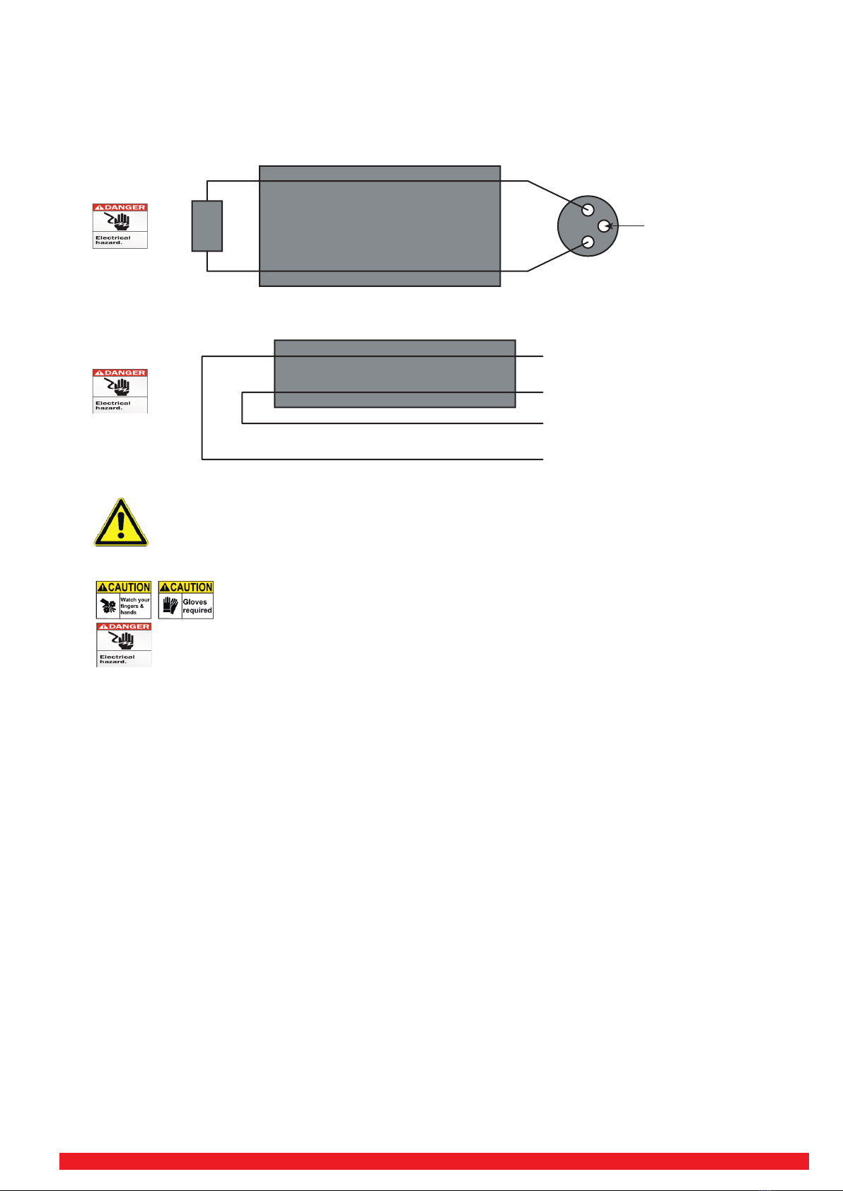
7 Handling/Storage:
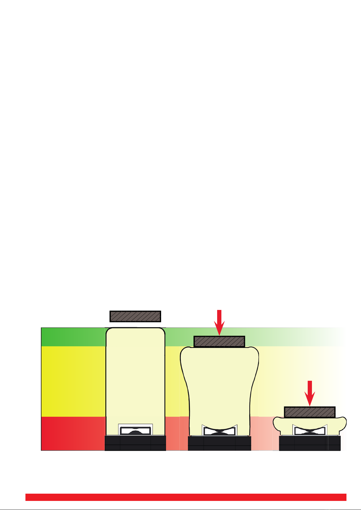
To avoid the risk of crushing, Safety gloves must be worn!
These are switch-sensi ve bumpers with integrated sensors that must not be damaged by external handling.
Please note:
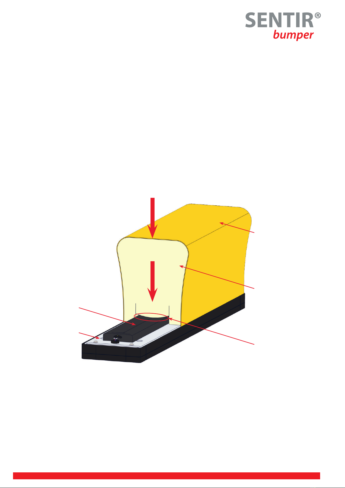
• Never reach into the bumper skin at any me!
• The bumper should not be pressed in or pressed!
• No lateral pressure should be exerted on the foam on the carrier plate!
Correct handling:
• Always carry the bumper with 2 persons!
• To li the bumper, apply light pressure on the edge of the carrier plate with the ball of your hand only!
• To mount the bumpers, adjust only with the palm of your hand!
• Do not drag SENTIR bumpers by their lead wire
• Never store outdoors
• Do not subject the SENTIR bumpers to undesirable stress
8 Installaon/Procedures:
To avoid the risk of crushing, Safety gloves must be worn!
Read all instruc ons rst before installing/se� ng up the Product!
Do not drink any alcohol or take any drugs before or during the setup of the Product and follow the safety
instruc ons carefully.
• Important: All installa ons, repairs and tests should be performed by a trained, responsible and authorized electrician.
• Unpack the SENTIR bumpers carefully and dont´t pull on the wires. Place the SENTIR bumpers in the planned posi ons with
the connec ng wires at the outer limits of the detec on zone.
• The control unit should be installed as supplied. It must not be modi ed or subjected to procedures or connec ons other
than those described with the instruc ons.
MOUNTINGINFORMATION
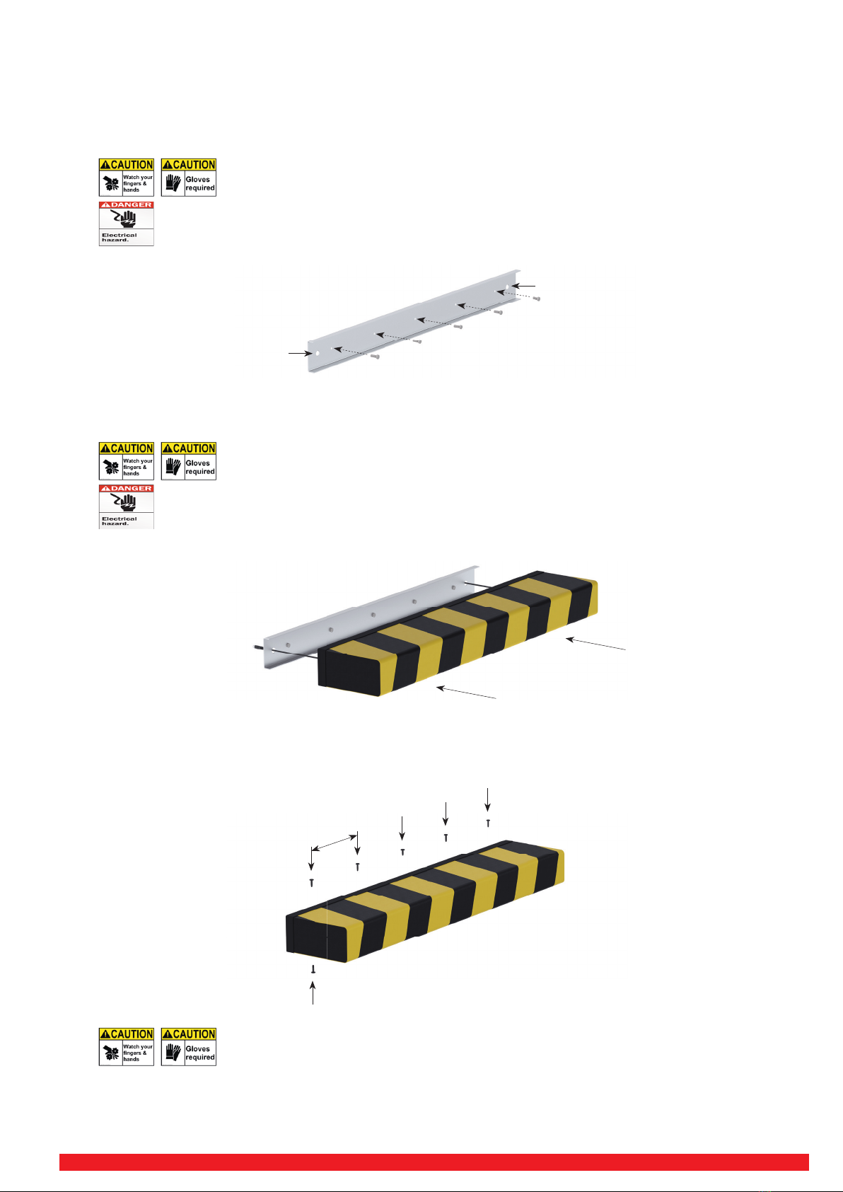
9 Preparaons/set-up:
To avoid the risk of crushing, Safety gloves must be worn!
Installa on and electrical work must be performed by authorized electricians.
• Posi on the bumper correctly. Bumpers may not be folded or bent. Safety-Contact-Bumpers may not be manipulated in any
way. Cut outs or shortening is not possible.
• The moun ng surface for the SENTIR bumpers has to be fl at, smooth, rigid, clean and dry and show no observable distor on
under the heaviest load an cipated. Undula ons, protrusions, large gaps or other irregulari es will increase the sensi vity
of the SENTIR bumpers and may result in intermi ent unintended switching o .
• Wiring must be in accordance with the Na onal Electric Code and applicable local codes and ordinances.
• Commissioning should be undertaken by a trained electrical technician experienced in safety installa ons.
• Ensure that the personnel understand that no addi onal coverings, boards, plates or planks are to be in the SENTIR bumper
during opera on of the machine.
!